Author Topic: My 427 SOHC Build..... Finally the time has come!  (Read 775970 times)

0 Members and 1 Guest are viewing this topic.

rowdy58ford

  • Newbie
  • *
  • Posts: 23
    • View Profile
Re: My 427 SOHC Build..... Finally the time has come!
« Reply #1335 on: February 24, 2016, 11:08:43 AM »
Jay, Rowdy 58 Ford Greg R here I would get a Gard specialists inc 9/16-12 C-900-200 1" long I ask how many foot lbs of torque can they take tech guy said twice what a grade 8 bolt can be torque two go to there site and see demo on how to install better then a ensert drill once then install no taps cuts it own threads best repair I can find? jay what spring set pressure do you use I have 250 on the seat I don't think I need that much now is the time to change had 3 bent exhaust valves they ground straight but I will replace no other damage but broke 5 rockers all exhaust

jayb

  • Administrator
  • Hero Member
  • *****
  • Posts: 7406
    • View Profile
    • FE Power
Re: My 427 SOHC Build..... Finally the time has come!
« Reply #1336 on: February 24, 2016, 02:23:50 PM »
Thanks for the tip on the thread repair Greg, I will check those out.  On my big SOHC I have about 270 on the seat and 660 over the nose, runs to 7500 with no problem with my heavy Manley valves (~150 grams).  If you are using relatively heavy valves I'd stick with the springs you've got.  I tried to go down to some PAC springs last summer, about 235/620, and I think I had some issues with them on the dyno, so I replaced them with the original springs and I'm sticking with those - Jay
Jay Brown
- 1969 Mach 1, Drag Week 2005 Winner NA/BB, 511" FE (10.60s @ 129); Drag Week 2007 Runner-Up PA/BB, 490" Supercharged FE (9.35 @ 151)
- 1964 Ford Galaxie, Drag Week 2009 Winner Modified NA (9.50s @ 143), 585" SOHC
- 1969 Shelby Clone, Drag Week 2015 Winner Modified NA (Average 8.98 @ 149), 585" SOHC


babybolt

  • Hero Member
  • *****
  • Posts: 516
    • View Profile
Re: My 427 SOHC Build..... Finally the time has come!
« Reply #1337 on: February 24, 2016, 09:51:28 PM »
Probably the longest single thread about an internal combustion engine ever, let alone a 427 SOHC!  1336 posts!

cobracammer

  • Hero Member
  • *****
  • Posts: 1165
    • View Profile
Re: My 427 SOHC Build..... Finally the time has come!
« Reply #1338 on: April 12, 2016, 01:22:18 PM »
Its that time!!  Comp Cams are done and have been delivered to Doc Brown!!  I can feel a dyno session right up around the bend!
Jason
2005 Saleen S281 (427 SOHC 2 X 4 EFI swap), T56 Magnum XL 6 speed, 9" Currie rear with 3.89 Gears

Drew Pojedinec

  • Hero Member
  • *****
  • Posts: 2116
    • View Profile
Re: My 427 SOHC Build..... Finally the time has come!
« Reply #1339 on: April 12, 2016, 02:33:35 PM »
so........ Finally, the time has come? 

cobracammer

  • Hero Member
  • *****
  • Posts: 1165
    • View Profile
Re: My 427 SOHC Build..... Finally the time has come!
« Reply #1340 on: April 12, 2016, 02:45:10 PM »
Jason
2005 Saleen S281 (427 SOHC 2 X 4 EFI swap), T56 Magnum XL 6 speed, 9" Currie rear with 3.89 Gears

machoneman

  • Hero Member
  • *****
  • Posts: 3853
    • View Profile
Re: My 427 SOHC Build..... Finally the time has come!
« Reply #1341 on: April 12, 2016, 02:56:29 PM »
Ooooh! Not that is a damn pretty sight indeed!  ;D
Bob Maag

jayb

  • Administrator
  • Hero Member
  • *****
  • Posts: 7406
    • View Profile
    • FE Power
Re: My 427 SOHC Build..... Finally the time has come!
« Reply #1342 on: April 17, 2016, 09:32:39 PM »
After finally getting the cams this week I was looking forward to getting the rest of this engine assembled over the weekend.  Got going bright and early Saturday morning, and of course ran into an immediate problem.  After installing the cams in the heads, then the gears on the cams, I started looping the big timing chain around the other gears to finish the timing setup.  But after getting the chain positioned correctly, when I tried to put some tension on the chain it didn't seem to be in the right position.  One of the things you always want to do with these engines is make sure that all the gears are lined up in the same plane.  If the gears are out of line with each other, you end up with side stresses on the chain, which will cause a premature chain failure.  When I laid the straight edge on the two cam gears and looked at the fuel pump gear, I saw the worst misalignment I'd ever seen on one of these engines:


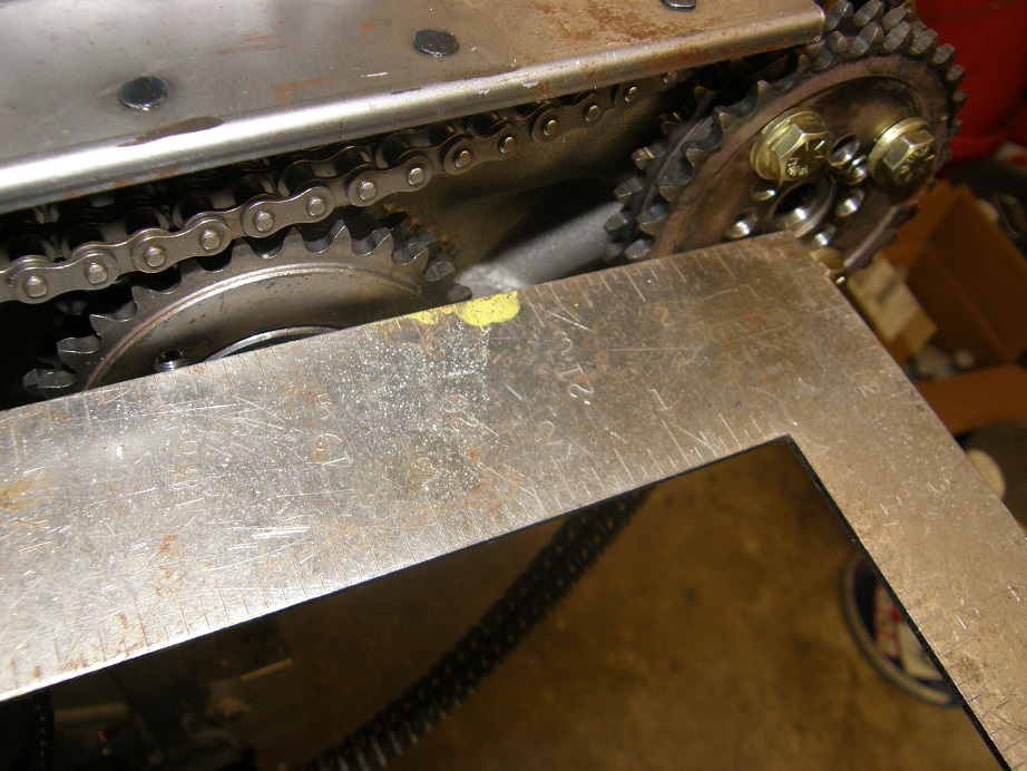
The fuel pump gear is a good 0.200" back from the two cam gears.  With that much out of plane deflection it is remarkable to me that the chain even ran for as long as it did.  A similar check on the adjuster gear showed that it was out of plane in the opposite direction, forward of the two cam gears, by about 0.100". 

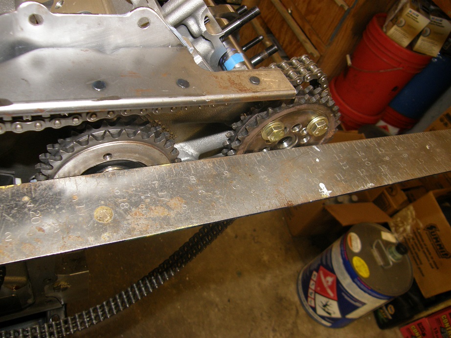
Fortunately, this is an easy fix.  The gears are pressed onto their bearings, and all that has to be done is to move them by pressing them forward or back into the correct position.  Easier said than done, of course, but after several trips back and forth to the press and multiple test fits, I finally got both the fuel pump gear and the adjuster gear positioned correctly.  Here's a picture shown the alignment of the fuel pump gear and the cam gear after the correction:


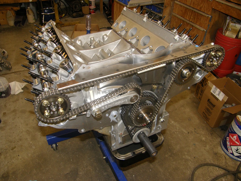
After resolving this issue the rest of the timing setup went together without any trouble.  We had already decided to replace the chain, so I assembled the new chain on the gears.  After waiting 3 months for the cams it was good to finally see the complete timing setup:


I spent the rest of the day Saturday installing the front cover and the oil pan.  The front cover can be challenging in some cases, especially if it is a new cover and has never been fit to the engine before, but since this engine was already together at one point, most of the fitment issues were worked out, and I was happy to see that after installation of all the gaskets, the cover slid neatly into position with no issues.  I did have an issue with one of the four bolts that holds the front cover to the backing plate up at the top, but it was just a stripped thread, and since on this particular front cover the holes did not go all the way through the cover at the top, I simply drilled the stripped hole deeper until it did come through, then tapped the drilled portion and put the bolt in.  One other odd thing about this cover has to do with the inspection covers that bolt in place on each side.  This is the second cover I've seen where the five smaller bolts that hold each inspection cover in place were tapped for fine threads.  The stock covers, and most of the aftermarket ones, are tapped with normal coarse threads. 

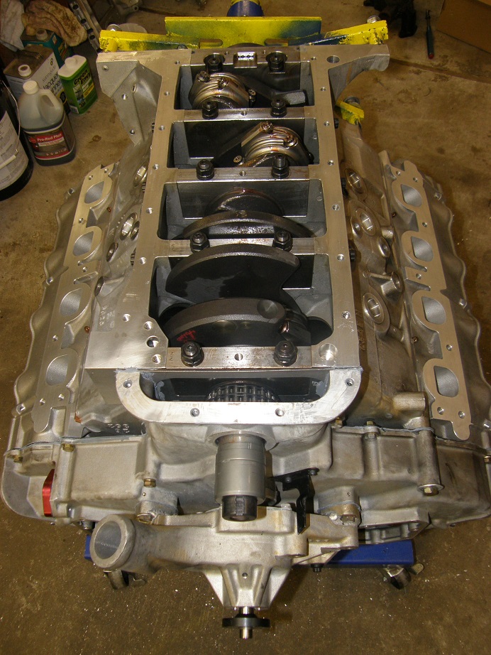
After the front cover was on I flipped the engine over to install the oil pan.  I've always liked the view of this engine from underneath:


The oil pan went on without any major issues, at least as much as it can with two gaskets, the windage tray, the long pickup tube and the extended sump LOL.  I called it a night on Saturday, fairly pleased with how the engine was going together.

Sunday morning I got the engine flipped back upright and started the tedious job of setting the cam timing.  I had checker springs installed on cylinder #1, so I used that cylinder to time the right cam, and also check piston to valve clearance once the timing had been set.  I remember earlier in this project Jason had struggled a little with finding top dead center, so I wanted to check that to be sure I knew that it was correct.  Jason had installed a timing tape over the degree marks on his harmonic balancer, but I was using a regular degree wheel bolted to the balancer.  After installing a piston stop in #1 and finding TDC, it looked like Jason's marks were within a 1/2 degree of where I had found TDC.  But then I noticed that the timing pointer on the harmonic balancer, which I had never removed, had been installed upside down.  When I unbolted it and flipped it over, it lined up pretty well with the original marks on the harmonic balancer, so I pulled the timing tape off and will refer to the marks on the balancer when timing the engine.

In the meantime I tensioned the chain, and after installing the cams straight up according to the marks, I checked the intake centerline of the right cam and found it to be 3 degrees retarded.  I wanted it at about 103, so I loosened the bolts on the right cam gear, pulled the pin, and then repositioned it to get close.  Checked it again and it was exactly 103, so I added Loctite to the bolts on the cam gear and tightened them.  Here's a picture of the setup in the midst of the cam timing operation:


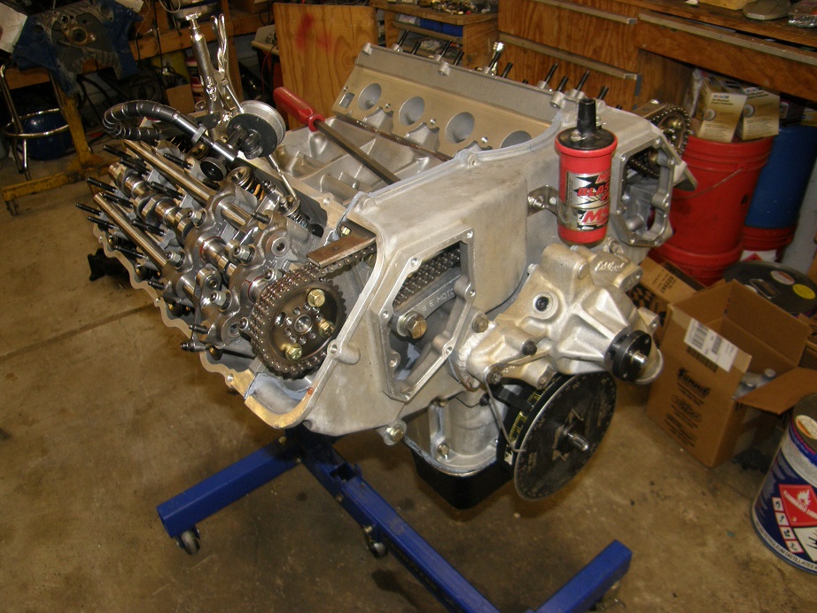
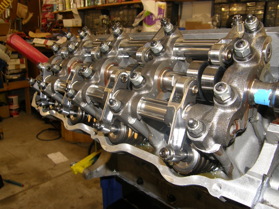
I went through the same procedure on the left cam, and set it at 105 degrees, then disassembled the right side and used my home built on-engine valve spring compressor to pull the checker springs and install the real valve springs on cylinder #1.  After that I spent the next hour or so installing the rocker shafts and rocker arms permanently, and then cold lashing the valves.  Then, in preparation for the pre-oil I installed the oil filter adapter, the oil filter, and a gauge on top of the oil filter adapter.

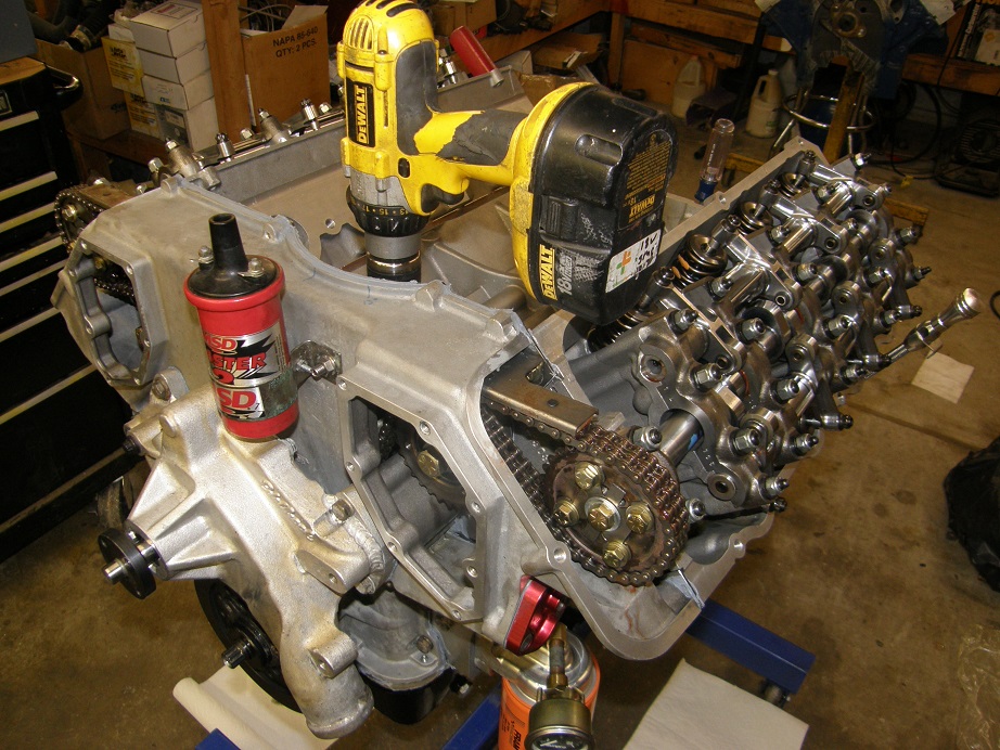
Pre-oiling the engine with the valve covers off is really important IMO, especially with these engines.  This is where you can confirm that ALL the rockers have oil, prior to the first engine start.  It is also a big mess on these engines, because the oil will overflow the heads and puddle under each exhaust rocker on the floor.  In preparation for that I had newspaper and paper towels down, to catch any oil that came pouring off the heads.  Here's a shot of the engine with my drill on a pre-oiling rod, ready to pre-oil the engine:


I added 8 quarts of oil to the engine, then spun the drill on low speed.  I was gratified to see that within 3 or 4 revolutions the drill was being dragged down by the pump.  The gauge read 65 psi, and the drill was probably only turning 100 RPM, so the oil pressure was looking good.  And sure enough, after 20 seconds or so I started hearing popping indicating air was coming out of the valvetrain, and then oil started pouring out.  This is what you want to see when you pre-oil one of these engines:


I checked to make sure that I had oil at all 16 rocker arms, and then stopped the drill.  Probably only lost a pint of oil on the floor  ;D


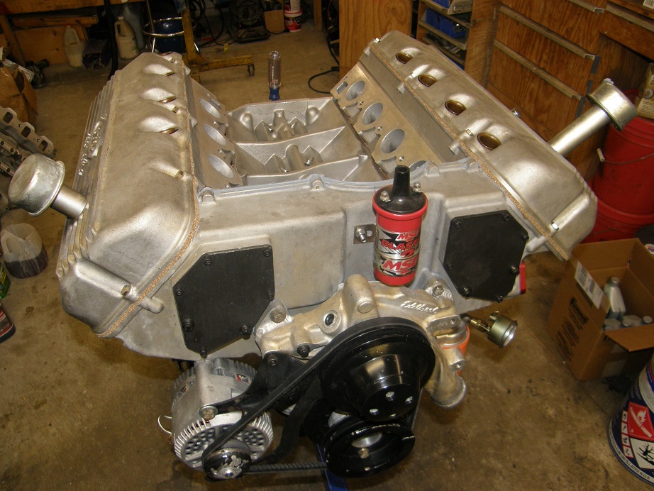
With all the valvetrain stuff now out of the way, the remaining work of buttoning up the engine seemed like it ought to be pretty easy.  And it was - right up to the intake manifold.  I test fit the intake, and the first thing I found was that it was sitting up way too high when the cork pieces were used on the end rails.  I like to use the cork pieces on the SOHCs because they fill a large triangular gap at each corner of the intake, but the flat part of the cork was holding the intake off the intake gaskets, and the bolt holes didn't line up.  So, I pulled the corks, set the intake in place on the gaskets, and everything seemed to fit fine.  So, I glued the gaskets in place with RTV, put a bead of RTV on each end rail, and set the manifold in place.  Then, and only then, did I discover that while the bolt holes in the manifold lined up with the heads at the back of the engine, they were misaligned at the front.  I made a futile attempt to bolt the intake in place anyway, but the bolts were just not going in.  Jason had stripped a bunch of these bolt holes in the head when he put the engine together, and now it was clear to me why.  Seemed like the only option was to enlarge or slot the holes in the intake, so that it could be bolted in place properly.  Reluctantly I pulled the intake off the engine and spent half an hour cleaning up all the TA-31 that was smeared everywhere.  As a result, here is the state of the engine tonight:


This week I will have to figure out the best solution for the intake dilemma, but once I have the intake bolted onto the engine, it is ready for the dyno.  Pretty sure at this point that I will get this engine dynoed next weekend.  Stay tuned...
« Last Edit: April 17, 2016, 09:35:40 PM by jayb »
Jay Brown
- 1969 Mach 1, Drag Week 2005 Winner NA/BB, 511" FE (10.60s @ 129); Drag Week 2007 Runner-Up PA/BB, 490" Supercharged FE (9.35 @ 151)
- 1964 Ford Galaxie, Drag Week 2009 Winner Modified NA (9.50s @ 143), 585" SOHC
- 1969 Shelby Clone, Drag Week 2015 Winner Modified NA (Average 8.98 @ 149), 585" SOHC


WConley

  • Hero Member
  • *****
  • Posts: 1160
  • No longer walking funny!
    • View Profile
Re: My 427 SOHC Build..... Finally the time has come!
« Reply #1343 on: April 17, 2016, 11:54:54 PM »
Cool deal Jay!  Thanks for the tip on checking sprocket alignment.  It seems such an obvious thing, but so easy to miss...

Looking forward to hearing a rumble from an Easterly direction next weekend.

- Bill
A careful study of failure will yield the ingredients for success.

cjshaker

  • Hero Member
  • *****
  • Posts: 4460
    • View Profile
Re: My 427 SOHC Build..... Finally the time has come!
« Reply #1344 on: April 18, 2016, 06:32:03 PM »
Looking at that shot of the right hand valvetrain, it becomes apparent the relation of the lobe in respect to the intake rockers. Since the cam is spinning clockwise, it seems that the cam lobe pushes almost directly against the horizontal plane of the intake rocker, unlike the exhaust where the lobe is coming from underneath. I'm amazed that the rockers roller can survive with that lobe/roller relationship. That has to become even more pronounced with higher lifts. Is that the cause of your previous rocker issues with the SOHC? Obviously premium quality materials MUST be used in those rollers to survive. I'd imagine the exhaust side has the same issue on the drivers side.

It also looks like the drivers side does not have a cam bearing in the first rocker shaft cap, whereas the passenger side does. Is that normal, or was it not installed yet while you were doing some checking?

It sure is sweet to get some quality second hand pictures of one of these engines going together, and to see all the indiosyncrasies of the SOHC. Thanks for these great write-ups.
Doug Smith


'69 R-code Mach 1, 427 MR, 2x4, Jerico, 4.30 Locker
'70 F-350 390
'55 Ford Customline 2dr
'37 Ford Coupe

machoneman

  • Hero Member
  • *****
  • Posts: 3853
    • View Profile
Re: My 427 SOHC Build..... Finally the time has come!
« Reply #1345 on: April 18, 2016, 07:45:25 PM »
Cool deal Jay!  Thanks for the tip on checking sprocket alignment.  It seems such an obvious thing, but so easy to miss...

Looking forward to hearing a rumble from an Easterly direction next weekend.

- Bill

2X on the sprocket alignment that few would have caught right away when setting up a SOHC for the first time. Jay needs to 'do' a new cammer only assembly book as it would be pure gold for Ford fans!
Bob Maag

jayb

  • Administrator
  • Hero Member
  • *****
  • Posts: 7406
    • View Profile
    • FE Power
Re: My 427 SOHC Build..... Finally the time has come!
« Reply #1346 on: April 18, 2016, 09:57:00 PM »
Looking at that shot of the right hand valvetrain, it becomes apparent the relation of the lobe in respect to the intake rockers. Since the cam is spinning clockwise, it seems that the cam lobe pushes almost directly against the horizontal plane of the intake rocker, unlike the exhaust where the lobe is coming from underneath. I'm amazed that the rockers roller can survive with that lobe/roller relationship. That has to become even more pronounced with higher lifts. Is that the cause of your previous rocker issues with the SOHC? Obviously premium quality materials MUST be used in those rollers to survive. I'd imagine the exhaust side has the same issue on the drivers side.

It also looks like the drivers side does not have a cam bearing in the first rocker shaft cap, whereas the passenger side does. Is that normal, or was it not installed yet while you were doing some checking?

It sure is sweet to get some quality second hand pictures of one of these engines going together, and to see all the indiosyncrasies of the SOHC. Thanks for these great write-ups.

There's kind of a story behind the rocker and cam lobe geometry.  You are correct that on the right side the lobe pushes against the intake rocker and pulls on the exhaust rocker, as the valves are opened.  Exact opposite on the left side of the engine.  This results in varying geometries from left to right.  Ford knew this, and the factory cams had different lobes for the left and right cams, to equalize the valve action.  But none of the aftermarket cam companies back in the day ever did that.

Fast forward to a few years ago, when Barry R and I got Comp Cams interested in doing these cams.  I had an SOHC sitting on the stand, and had several of the early version Comp Cams sitting here, so I did a degree by degree measurement of an intake lobe and an exhaust lobe, one on each side of the engine, and forwarded the data to Billy Godbold at Comp.  The result was a change to the lobe profiles for their newest series of SOHC cams.  Now, when you order an SOHC cam from Comp, the lobe numbers for the left cams start with LE and LI, and the lobe numbers for the right cams start with RE and RI, because the lobes are different from side to side to compensate for the valve geometry variation.

The rocker issues I've had haven't had much to do with this, though.  Mostly they have been due to sloppy tolerances and inadequate parts in the rockers.  T&D was the first company that put an SOHC rocker together with the same needle bearing tolerances that you would see with a roller lifter, and that made the rockers live for a longer term on the street.

You are correct also about the missing cam bearing in the #2 position on the left side of the engine.  For some reason, Ford left that one out.  Go figure...
Jay Brown
- 1969 Mach 1, Drag Week 2005 Winner NA/BB, 511" FE (10.60s @ 129); Drag Week 2007 Runner-Up PA/BB, 490" Supercharged FE (9.35 @ 151)
- 1964 Ford Galaxie, Drag Week 2009 Winner Modified NA (9.50s @ 143), 585" SOHC
- 1969 Shelby Clone, Drag Week 2015 Winner Modified NA (Average 8.98 @ 149), 585" SOHC


jayb

  • Administrator
  • Hero Member
  • *****
  • Posts: 7406
    • View Profile
    • FE Power
Re: My 427 SOHC Build..... Finally the time has come!
« Reply #1347 on: April 24, 2016, 10:20:07 PM »
Finally today I finished up with this engine.  It has been a long wait, especially for the cams, but now that it is finally together it was great to have it run well on the dyno.  Here's a video of one of the dyno pulls:

https://youtu.be/Hw5_dfg8FjA

First thing I had to do this week was to get the intake manifold holes slotted so that the intake would physically fit on the engine.  This entailed setting it up on one of my CNC machines as shown in the photo below:


This is not the ideal setup because the intake can vibrate while the tool is cutting, but I went slowly and finally got both sides slotted.  Here's a picture of one of the holes, while I was test fitting the intake after machining:


The test fit looked good, so on Saturday morning I started finishing up the engine.  Everything went pretty well except for the plug wires.  Jason used regular MSD wires, and you really need to use some wires with a rigid boot instead, in order to reach down into the spark plug tube with the wire and make a secure connection to the plug.  Taylor Hemi wires are the ones I like to use; here's a picture showing the regular MSD wires and one of my Taylor wires:


In order to make connections to the plug I had to reach down into the tube with a needle nose pliers and push the boot onto the plug.  Not that big of a deal, but it took a while to make sure I had them all right.  I also pulled back the caps that go over the spark plug tubes to allow access for the pliers.  But after the wires were installed the engine was basically complete; here it is sitting on the stand, waiting to go on the dyno:


I spent the rest of the afternoon Saturday getting the engine installed on the dyno and all hooked up.  By the end of the night, it was ready:


The dyno session was mostly uneventful.  The engine fired right up with no drama, had good oil pressure (over 50 psi hot at 1500 RPM, and over 70 psi during the dyno pulls), and sounded really good.  No funny noises, no clattering, etc.  After warming the engine up for several minutes I shut it down, and then lashed all the valves and tensioned the timing chain.  We were ready for some dyno pulls.

During the warm up for the dyno pulls, I revved the engine a few times, and noticed that the oil pressure was dropping.  I had been afraid of something like this; the rear sump Canton pan on this engine is known for draining the sump and losing oil pressure during the pull.  I used this pan in 2008 and noticed the problem, and Robert Pond told me the same thing happened to him with this pan.  I had added capacity to the pan to hopefully avoid this problem, but apparently it was not completely solved.  I was running 8 quarts of oil in the pan, so before the first dyno pull I added another quart.  We ran the first pull from 3000 to 4500 RPM, and didn't see any issues with the oil pressure.  However, the engine was way down on power, and it took us a while to find the issue.  Finally with the help of my friend Steve I figured out that I had the ignition timing wrong; after that was corrected, the engine ran much better and started making power like it should.  However, once we started running pulls to 5500 RPM plus, the oil pressure started dropping at the end of the pull.  Once again I added another quart of oil, and the problem went away.  I'm certain that a normal front sump pan with some baffles would solve this problem, but a pan like that won't fit in Jason's car.  I emailed him earlier and suggested just running 8 quarts in the pan plus a 3 quart Accusump, which I think would solve this problem. 

The dyno results were a little less than what I was hoping for, but because of the oil pan issues I did not want to run the engine past 6500 RPM, and horsepower was still climbing at that point, so I'm thinking the dyno results were a little light on what this engine would actually do if we could really wring it out.  I was hoping for 650 HP, but peak HP was 625, and peak torque was around 555 foot pounds.  Also, the cams on this engine have quite a bit less duration than the stock cams, and about the same lift, so we gave away a little horsepower there.  What we gained was low speed performance and vacuum.  This engine idles easily at 900-1000 RPM, and makes 9 to 11 inches of vacuum at idle.  Anybody who has been following the self learning EFI thread knows that low vacuum at idle will not let those systems work properly, and Jason has one of those systems for this engine, so I'm thinking that the EFI system ought to work pretty well with the engine as it is.  Here's a couple of torque and power graphs, for different RPM ranges:


With that flat torque curve down low this engine ought to smoke the tires with impunity LOL!  I'm looking forward to getting it back to Jason so he can put it in the car and start enjoying it.


Jay Brown
- 1969 Mach 1, Drag Week 2005 Winner NA/BB, 511" FE (10.60s @ 129); Drag Week 2007 Runner-Up PA/BB, 490" Supercharged FE (9.35 @ 151)
- 1964 Ford Galaxie, Drag Week 2009 Winner Modified NA (9.50s @ 143), 585" SOHC
- 1969 Shelby Clone, Drag Week 2015 Winner Modified NA (Average 8.98 @ 149), 585" SOHC


57 lima bean

  • Guest
Re: My 427 SOHC Build..... Finally the time has come!
« Reply #1348 on: April 25, 2016, 11:27:17 AM »
The alleged locked distributor turned out to be a hoax.I vote the engine stays North and installed in my car so I can return to FE power and be somebody again.
« Last Edit: April 25, 2016, 11:38:07 AM by 57 lima bean »

jayb

  • Administrator
  • Hero Member
  • *****
  • Posts: 7406
    • View Profile
    • FE Power
Re: My 427 SOHC Build..... Finally the time has come!
« Reply #1349 on: April 25, 2016, 11:33:57 AM »
Is that a Checker?   ;D ;D
Jay Brown
- 1969 Mach 1, Drag Week 2005 Winner NA/BB, 511" FE (10.60s @ 129); Drag Week 2007 Runner-Up PA/BB, 490" Supercharged FE (9.35 @ 151)
- 1964 Ford Galaxie, Drag Week 2009 Winner Modified NA (9.50s @ 143), 585" SOHC
- 1969 Shelby Clone, Drag Week 2015 Winner Modified NA (Average 8.98 @ 149), 585" SOHC