Author Topic: My 427 SOHC Build..... Finally the time has come!  (Read 775939 times)

0 Members and 1 Guest are viewing this topic.

jayb

  • Administrator
  • Hero Member
  • *****
  • Posts: 7406
    • View Profile
    • FE Power
Re: My 427 SOHC Build..... Finally the time has come!
« Reply #1290 on: January 24, 2016, 09:48:47 PM »
Finally got some work done on this project this weekend, and of course ran into another setback  :(  Before I go into the details, I want to address something that Joe mentioned, regarding cutting the seats to bring them back flush with the chamber, assuming that they were originally proud of the chamber surface.  I thought that was a good idea and that it might remove the chipped areas of the seat, so this week when I went to the shop to pick up the crank, I took a closer look at the heads.  Unfortunately, the broken parts of the seat were well below the chamber surface, and a straightedge placed on the final cut on the seat lined up perfectly with the chamber surface.  From this it appears to me that the seats were not originally proud of the chamber surface, and they just disintegrated of their own accord.  In any case, we will be replacing those sub-standard powdered metal seats with more performance oriented ductile iron seats.

The crank work had taken a lot longer than I expected, and I found out why when I picked it up.  It turns out that because the #3 main bearing was not oiling in this engine, the thrust surface of the crank was starved for oil.  It was fairly significantly worn, something like .020" beyond spec.  So, instead of just grinding the crank 10/10 and making it ready for assembly, the thrust surface of the crank had to be welded, then machined back into spec, before the crank could be ground 10/10.  But finally it was done, and I brought it back home to get ready to re-assemble the short block.

Yesterday afternoon I got started with rebuilding this engine.  I pulled out all the plugs, and scraped most of the remaining gasket material and sealer from the block, and then started work on the cam bearings.  I had previously looked at the #2 and #4 cam bearings and knew that they didn't have the proper holes to line up with the oil galleries in the side oiler block.  However, when I pulled out the #3 cam bearing, I was surprised to see that the #3 bearing did have the proper holes for the #2 or #4 positions!  So it appears that whoever put the cam bearings in this block did have the correct set, because one of the bearings was for a side oiler.  Since there is no #5 cam bearing in the Pond block, probably the shop just didn't install the other cam bearing with the multiple holes.  Bottom line is whoever put the cam bearings in this block really had no idea what they were doing. 

I went ahead and installed the new cam bearing set that Jason had provided.  I was very careful to make sure that the oil holes for the #2 and #4 cam bearings lined up properly with both holes in the block.  I like to put a welding rod down through the hole in the block deck, and see it slide into the cam bearing bore, to prove to myself that the holes are lined up correctly.  I took a picture of each of the key cam bearings with the welding rod stuck through it; photos below:


Next I installed the #3 cam bearing, making sure that the oil hole in the block was NOT lined up with the hole in the bearing (this was another major error in the original shop's cam bearing installation, because of course there is no #3 journal on the stub cam, so oil just spit out of the hole into the crankcase, failing to oil the #3 main bearing).  Finally I installed the front cam bearing, making sure both holes lined up there also.  The front cam bearing was the only one that the original shop had installed correctly.

I don't know why, but for some reason when I'm laying in bed trying to get to sleep, I get to thinking about the current project and potential problems and/or solutions will come to me.  Saturday night, for some reason, I started thinking about the #1 cam bearing.  I realized I hadn't checked for distributor clearance after I'd installed it.  In some cases with aftermarket blocks and their required cam bearings, the cam bearing will protrude into the hole for the distributor, blocking the distributor installation.  I made a mental note to check for that before I fell asleep.

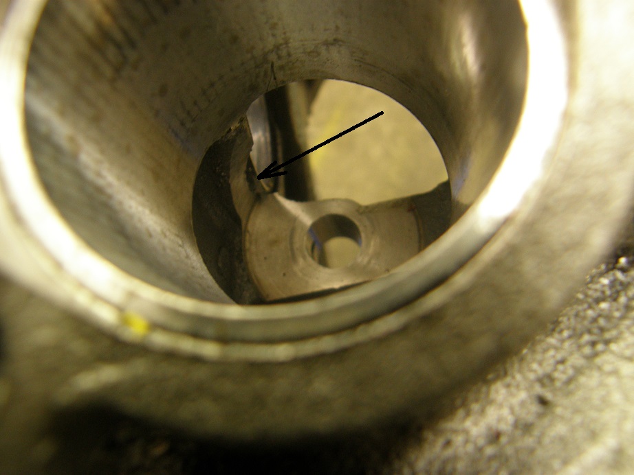
Sunday morning, first thing I did was flip the block over and look in the distributor hole.  Sure enough, there was the cam bearing sticking into the distributor hole!  See the arrow in the picture below:


The distributor wasn't going to go in like that.  I pulled the front cam bearing back out, and compared it to the one that I had previously removed:


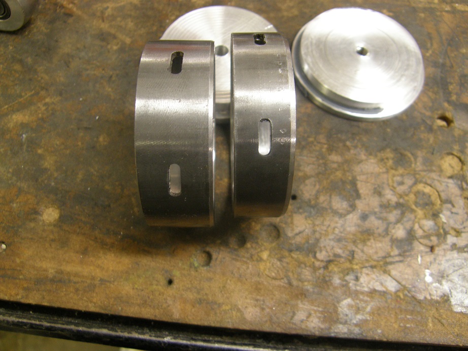
The new bearing was much, much wider than the original bearing.  Fortunately, since the original bearing had gotten a good supply of oil when the engine was running, it was in very good shape, so rather than try to modify the new bearing to fit, I re-installed the original bearing to solve the problem.

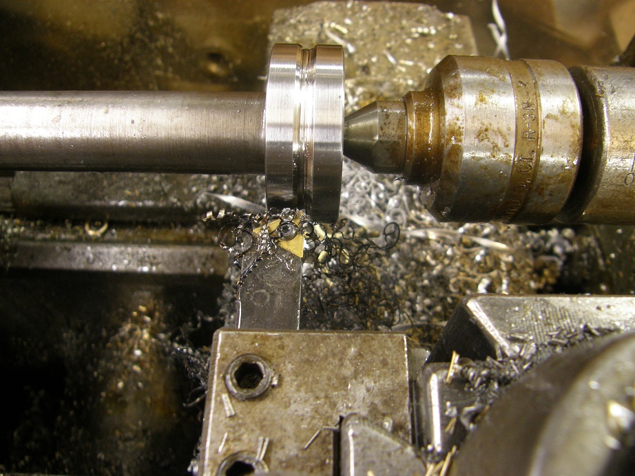
Next I installed the aluminum block-offs for the #4 cam bearing, to keep the oil from coming out into the crankcase.  These are the two discs visible behind the cam bearings in the previous photo.  They bolt together around the #4 cam bearing, and have a gap between them so oil from the block can transfer through that gap to the cylinder head.   After that, I took a look at the stub cam assembly.  I decided that I wanted to make the groove in the stub cam a little wider.  I like to do this on all the SOHCs I build, to compensate for any misalignments between the stub cam and the #2 cam bearing.  I ended up making the stub cam groove 0.230" wide; here's a picture of it on my lathe during the machining operation:


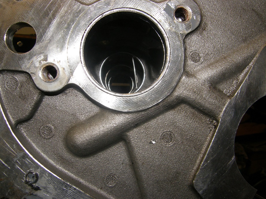
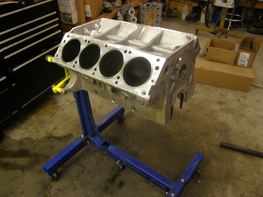
After machining the stub cam I test fit it in the block and it fit perfectly.  I reinstalled the remaining plugs, spent some time removing a broken off bolt in the front of the engine, and then got ready to start checking bearing clearances.  Here's a picture of the block ready to assemble:


I pulled the new crank out of the box and set it up on the bench.  I miked the main journals and they were just about perfect, right on 2.738, give or take a tenth.  I used the micrometer to set up my dial bore gauge, then one by one started checking the inside diameter of the main bearing bore.  Starting from the back of the engine, I checked the #5 main bearing and found the clearance a little large, at .0042".  Next I went to #4, and after tightening the main cap and torquing to the spec, I measured a much better clearance of .0026".  However, I noticed that the clearance would change as I moved the dial bore gauge from the front of the bearing toward the back.  After looking at this fairly carefully, I saw a difference of nearly .001".  So the bore was tapered; at the very front the clearance measured .0022", and at the rear of the bearing the clearance measured .0032".  This was not good.

Next I moved to the #3 main, and here the problem was even worse.  Front side of the bearing showed a clearance of .0015", and the rear showed a clearance of .0033"!

Well, at this point I was wondering whether there was some problem with the bearings, or if it was with the block.  I decided to pull the #3 cap back off, remove the bearings, and mike the bearing bore in the block itself.  Now on this engine, the main caps are held in place by studs, except for one bolt that is used on one side of the #3 cap.  Jason installed this bolt because it has a stud on top of it, and can be used to bolt the long oil pump pickup tube in place (required for the rear sump on this engine.)  However, you are of course putting the full torque of the main cap bolts into the aluminum threads in the block.  This is not really a good idea, and is why aluminum blocks come with studs to secure the main caps and heads, not bolts.  So, naturally, as I was torquing down this bolt to tighten the cap, when I got to about 80 ft pounds I started to feel it slip.  I knew immediately that I'd stripped the threads in the block.  In order to continue with the check, I left the bolt as it was, and tightened the nut on the stud on the other side, plus the crossbolts.  Then I set the dial bore gauge up to measure the inside main bearing bore, and sure enough, I still had the same taper as I had measured with the bearing in place.

I went back to the bolt on #3, and just to be sure I tried to tighten it again.  No joy, it spun easily.  We pulled the cap off and also took the #3 stud out, and put them in the cap.  Here's a photo:


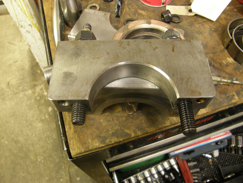
The bolt is also not going deep enough into the block, compared to the stud.  I'm going to find a way to make a stud work in this position so this problem does not recur.

So, the block needs to have the main cap thread helicoiled, and be align honed before we can continue assembly, and I will get it back into the shop this week.  Maybe we can get a quick turnaround and be back to assembly next weekend; we will see.  I'll post an update when I get back to assembly of the short block - Jay
Jay Brown
- 1969 Mach 1, Drag Week 2005 Winner NA/BB, 511" FE (10.60s @ 129); Drag Week 2007 Runner-Up PA/BB, 490" Supercharged FE (9.35 @ 151)
- 1964 Ford Galaxie, Drag Week 2009 Winner Modified NA (9.50s @ 143), 585" SOHC
- 1969 Shelby Clone, Drag Week 2015 Winner Modified NA (Average 8.98 @ 149), 585" SOHC


ScotiaFE

  • Hero Member
  • *****
  • Posts: 1409
  • Howie
    • View Profile
Re: My 427 SOHC Build..... Finally the time has come!
« Reply #1291 on: January 24, 2016, 10:47:11 PM »
Once you get the block thread repaired you could drill and tap a proper stud and
either use a stud or bolt for the for the oil pickup hold down.
One issue with the coil repair is it is only about 1/2" long or so.
This is where you could use a 5/8 fine thread bolt and drill and tap it for the 1/2" thread the whole length
of the block thread. It will have a .028" wall when done and when glued in you would pretty much have to drill it out
to remove it.  :P
I know you can get extended length coils, but they are still coils. ::)
And you still have to torque the stud a min of 3 more times.

BH107

  • Sr. Member
  • ****
  • Posts: 305
    • View Profile
Re: My 427 SOHC Build..... Finally the time has come!
« Reply #1292 on: January 26, 2016, 12:21:42 AM »
Once you get the block thread repaired you could drill and tap a proper stud and
either use a stud or bolt for the for the oil pickup hold down.
One issue with the coil repair is it is only about 1/2" long or so.
This is where you could use a 5/8 fine thread bolt and drill and tap it for the 1/2" thread the whole length
of the block thread. It will have a .028" wall when done and when glued in you would pretty much have to drill it out
to remove it.  :P
I know you can get extended length coils, but they are still coils. ::)
And you still have to torque the stud a min of 3 more times.

Agree, you should be able to drill and tap the end of a stud to hold up pickup...

As far as the thread repair, obviously fine thread isn't going to work in an aluminum block. I'm sure the machine shop will probably use a TimeSert or similar, and they are available in longer lengths than most of the coil type repairs.

ScotiaFE

  • Hero Member
  • *****
  • Posts: 1409
  • Howie
    • View Profile
Re: My 427 SOHC Build..... Finally the time has come!
« Reply #1293 on: January 26, 2016, 10:58:01 AM »
I know what your saying "fine thread in alum", no way giddy up.
But the fine thread is used quite a bit in aerospace parts and even in alum rods.
I have no problem using it in aluminum.
I would make a fitted threadsert for the block. I would want to remove the minimum amount
of block material and make the thinnest threadsert I could.
Of course it will be Jays call as he is the one who has to post pictures.  ::)

jayb

  • Administrator
  • Hero Member
  • *****
  • Posts: 7406
    • View Profile
    • FE Power
Re: My 427 SOHC Build..... Finally the time has come!
« Reply #1294 on: January 26, 2016, 11:55:06 AM »
I'm leaving it up to my shop; they are the ones with the experience on this, so whatever they do is OK by me.
Jay Brown
- 1969 Mach 1, Drag Week 2005 Winner NA/BB, 511" FE (10.60s @ 129); Drag Week 2007 Runner-Up PA/BB, 490" Supercharged FE (9.35 @ 151)
- 1964 Ford Galaxie, Drag Week 2009 Winner Modified NA (9.50s @ 143), 585" SOHC
- 1969 Shelby Clone, Drag Week 2015 Winner Modified NA (Average 8.98 @ 149), 585" SOHC


philminotti

  • Full Member
  • ***
  • Posts: 115
    • View Profile
Re: My 427 SOHC Build..... Finally the time has come!
« Reply #1295 on: January 26, 2016, 08:29:08 PM »
When I originally bought my Pond block in 2005 from an engine shop who shall remain nameless, the mains were all tapered as well.  Had to crate it up and send it back.

cjshaker

  • Hero Member
  • *****
  • Posts: 4460
    • View Profile
Re: My 427 SOHC Build..... Finally the time has come!
« Reply #1296 on: January 27, 2016, 12:38:19 AM »
I'm not even sure how the heck you would get tapered mains like that when a boring bar is used?
 Either way, with an aftermarket block everything needs to be checked and you have to expect some touch-up work here and there. Good catch on that though, it would surely have caused some bearing problems in a short period.
Doug Smith


'69 R-code Mach 1, 427 MR, 2x4, Jerico, 4.30 Locker
'70 F-350 390
'55 Ford Customline 2dr
'37 Ford Coupe

ScotiaFE

  • Hero Member
  • *****
  • Posts: 1409
  • Howie
    • View Profile
Re: My 427 SOHC Build..... Finally the time has come!
« Reply #1297 on: January 27, 2016, 10:31:18 AM »
From worn stones.
Short stroking and the leading portion wears and allows the taper to form.

Heo

  • Hero Member
  • *****
  • Posts: 3287
    • View Profile
Re: My 427 SOHC Build..... Finally the time has come!
« Reply #1298 on: January 27, 2016, 01:00:55 PM »
With alu block and steel mains
I dont think its Honed with Stones
Its bored with a Boring bar
But how it get tapered??
Maby worn Cutting tools so there is
a lot of heat prodused so the mains
Grow during the Boring operations
And then cools down to tapered
Just a thought


The defenition of a Gentleman, is a man that can play the accordion.But dont do it

ScotiaFE

  • Hero Member
  • *****
  • Posts: 1409
  • Howie
    • View Profile
Re: My 427 SOHC Build..... Finally the time has come!
« Reply #1299 on: January 27, 2016, 01:33:43 PM »
You could just go with a bore, but even a really nice bar will show tool marks and pretty much requires a hone to clean the surface.
The aluminum steel combo needs a bit more finesse but it normally still gets a hone for final size.
The cap that Jay shows in this thread has the tell tale signs of the hone cross hatch.
When the tool goes dull it does not matter how fancy the machine or the operator, it's going to start
cutting tapers. ;)

Barry_R

  • Hero Member
  • *****
  • Posts: 1915
    • View Profile
    • Survival Motorsports
Re: My 427 SOHC Build..... Finally the time has come!
« Reply #1300 on: January 27, 2016, 06:02:13 PM »
Almost always a hone.  If they have a taper its likely that the main cap was not cut perpendicular to the bore in the first place - every time you reassemble it ends up in a slightly different location/orientation.  The line hone uses a really long set of stones with a pretty long stroke...

jayb

  • Administrator
  • Hero Member
  • *****
  • Posts: 7406
    • View Profile
    • FE Power
Re: My 427 SOHC Build..... Finally the time has come!
« Reply #1301 on: January 30, 2016, 09:33:14 PM »
Got the block back from the machine shop on Friday; thankfully it was a quick turnaround.  In addition to the line hone they also faced the thrust surfaces of the cap and block, because they were a little banged up.  Got back on this project tonight and finally making some progress.  All the bearing clearances were around .003" on the mains, so they looked good, but after a test assembly the crank endplay was almost non-existent; I measured it at .001"!  I took the thrust surfaces of the #3 bearing and sanded them on a glass plate to increase the clearance, then FINALLY got the crank installed and torqued into the block:


Hopefully the rods and pistons will go in without drama tomorrow...
Jay Brown
- 1969 Mach 1, Drag Week 2005 Winner NA/BB, 511" FE (10.60s @ 129); Drag Week 2007 Runner-Up PA/BB, 490" Supercharged FE (9.35 @ 151)
- 1964 Ford Galaxie, Drag Week 2009 Winner Modified NA (9.50s @ 143), 585" SOHC
- 1969 Shelby Clone, Drag Week 2015 Winner Modified NA (Average 8.98 @ 149), 585" SOHC


turbohunter

  • Hero Member
  • *****
  • Posts: 2509
    • View Profile
Re: My 427 SOHC Build..... Finally the time has come!
« Reply #1302 on: January 31, 2016, 12:06:42 AM »
Hope it doesn't fight you the whole way.
Marc
'61 F100 292Y
'66 Mustang Injected 428
'66 Q code Country Squire wagon


cobracammer

  • Hero Member
  • *****
  • Posts: 1165
    • View Profile
Re: My 427 SOHC Build..... Finally the time has come!
« Reply #1303 on: January 31, 2016, 11:28:04 PM »
I was also noticing the #3 replacement stud.  Is that one just a little longer " out of the box", or did it require a little tinkering?  Should work well with the rear oil pickup. ;D
Jason
2005 Saleen S281 (427 SOHC 2 X 4 EFI swap), T56 Magnum XL 6 speed, 9" Currie rear with 3.89 Gears

jayb

  • Administrator
  • Hero Member
  • *****
  • Posts: 7406
    • View Profile
    • FE Power
Re: My 427 SOHC Build..... Finally the time has come!
« Reply #1304 on: February 01, 2016, 12:11:40 AM »
That stud is actually for a 351W Ford block; I traded the new one I got from Robert Pond to my machinist for that one.  It is about 3/8" longer, so it should work just fine to secure the oil pickup tube.  Didn't get as much done today on your engine as I wanted, but the first three piston and rod assemblies are in, and rod bearing clearance looks good so far.  Should be able to get the rest of the pistons and rods in this week, then hopefully have the heads by next weekend, and get those assembled and installed...
Jay Brown
- 1969 Mach 1, Drag Week 2005 Winner NA/BB, 511" FE (10.60s @ 129); Drag Week 2007 Runner-Up PA/BB, 490" Supercharged FE (9.35 @ 151)
- 1964 Ford Galaxie, Drag Week 2009 Winner Modified NA (9.50s @ 143), 585" SOHC
- 1969 Shelby Clone, Drag Week 2015 Winner Modified NA (Average 8.98 @ 149), 585" SOHC