This week was a fairly productive one on the new car project. Last week I had gotten stalled on finishing up the steering installation due to different thread size on the manual rack as compared to the power rack, and the requirement to make a rack extension incorporating these threads. On Wednesday I received the tap and die for the 16mm X 1.0mm thread size I'd ordered from McMaster Carr, and also the 4130 chrome moly steel to make the extension. Wednesday night I snuck out to the shop rather late and got the 16mm bar threaded up about an inch, which was going to be needed for the extension. Thursday night I had a little free time after the kids went to bed, so I thought I would drill the 1 1/4" bar with the 15mm drill bit I had purchased. Unfortunately I ran into a problem with this, because the drill bit wasn't necked down at all to fit into the chuck, and the chuck for the tailstock of my lathe would only go up to 1/2" (about 12.7mm).
I thought about drilling the hole 9/16" and then boring it the rest of the way to 15mm (0.590"), but my small boring bar isnt' that stable, and I had to bore the hole a long way, so I didn't feel that this was a reasonable option. The best option would be to purchase a new chuck for the tailstock that would hold a larger drill bit. Buying new tools is always a double edged sword for me; on one hand, I hated the idea of spending a bunch of money on a new chuck just to drill one hole, but on the other hand, as a confirmed tool junkie, I love getting new tools!
I decided to go ahead and buy a new chuck. I went through the Enco web site and found a cheap chuck with a capacity of 1/8" through 3/4", and also the adapter required to fit the #4 Jacob's taper hole in the back of the chuck and the #3 Morse taper of my lathe's tailstock. Friday morning I called Enco and paid the usual exorbitant fee to get the parts shipped and delivered to me on Saturday; I was really keen on getting the rack extension made and the steering system finished up over the weekend.
Saturday morning my wife and kids were off at a basketball game, so I had some free time in the shop. The new chuck and adapter had not arrived yet, so I decided to tackle a project that I had been putting off. Part of the firewall of a '69 Mustang extends out into the engine compartment farther than the rest of the firewall, and I wanted to cut this piece out and replace it with a flat piece of sheet metal to give me more room behind the engine. I hate sheet metal work, so I decided to tackle this project right away while I was fresh, and hopefully get it finished up fairly quickly. After crawling into the engine compartment and using some straightedges to determine where to cut the firewall, I cut the hole with a circular cut-off wheel in my 4 1/2" grinder. After trimming the hole the engine compartment looked like this:
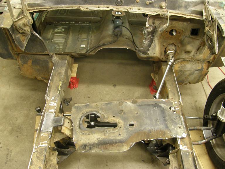
The piece of the firewall that I removed is shown in the foreground of the photo. I used this piece as a template, and transferred its shape onto a piece of 20 gauge steel sheet. After cutting this out and test fitting it, I trimmed it a little for a better fit and put some bends into it at the edges so it would fit the opening. Then I positioned it over the hole with a few klecos; photo below:
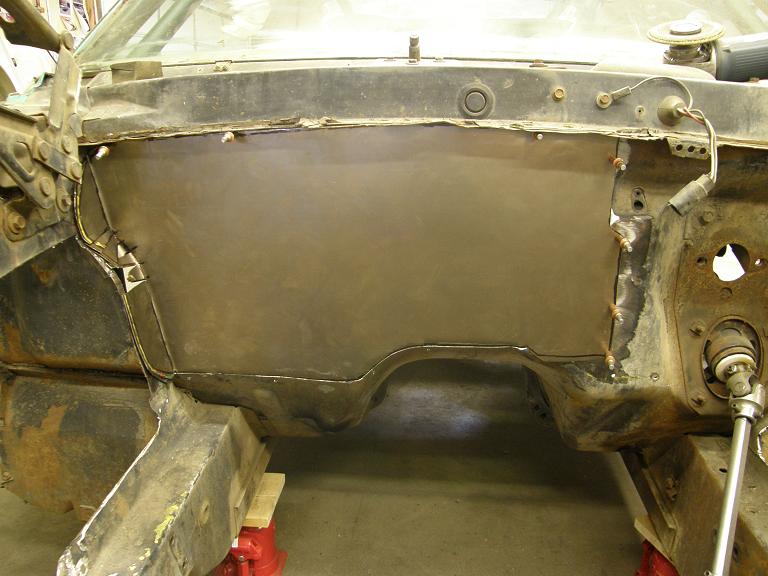
The bent section at the left side of the photo had a bunch of cuts in it where I'd had to bend it, in order to make it go around a corner. After this photo was taken I decided to pull the panel back off again and cut those pieces out completely; later after the panel was tacked in place, I made up a single small piece of sheet metal to fill the hole where the cut pieces were removed. After replacing the panel and reinstalling the klecos to hold it in position I tack welded all the way around the outside of the panel, in small buttons, kind of like I had done with the quarter panel installation. This was a long, tedious job; did I mention I hate sheet metal work? Anyway, when I was taking a break I looked out the window of the shop and there was a suspicious looking box on the front steps of my house. Hmmm, probably my Enco order. I forced myself back to welding for another half hour or so, but then decided I could always finish this later when I was doing the final cleanup and painting of the engine compartment, so I put the welder away and went to get the UPS delivery.
Within five minutes of bringing the box into the shop I had the new chuck installed in the lathe and the 15mm hole drilled in the 1 1/4" bar. That was easy. Next I had to counter bore the hole for a distance of 3/4" or so, so that it would fit over the end of the existing rack and self-align. After that was finished I used my new 16mm X 1.0mm tap to tap the 15mm hole. I started it by holding the tap in the tail stock to make sure that the hole was tapped straight, and tapped it to a distance of about 3/4" using a tap handle. On Wednesday night I had used my 16mm X 1.0mm die to make a threaded rod 1 1/2" long, so once I had the hole tapped I screwed the threaded rod into place with a bunch of red Loctite to hold it solidly in place. I went in the house for lunch while the Loctite dried, and then after lunch came back out and cut the rack extension off to the correct length, and tapped the other end. Finally, using some blue Loctite I installed it on the passenger side of the rack.
Saturday night I got some more time in the shop, so I worked on the passenger side front suspension modifications, similar to the driver's side I had done last weekend. This was cutting the top bearing housing and modifying the upper coil spring mount for more strut travel, plus enlarging the strut mounting holes and making the plate that the strut would come through. On Sunday I wanted to get the whole front suspension mock up finished, now that I had the pieces to finish the rack.
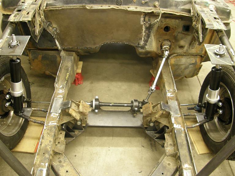
Sunday morning I got to work assembling the passenger side front suspension, and got everything tacked into position. After I did that, I screwed the tie rod ends into the rack to see how the whole thing looked:
Now that I had the spindles in position on both sides of the car, I could measure for the correct amount to cut off the tie rods. The original Fatman kit had specified that 4 1/2" be cut off the tie rods, and the ends rethreaded. I had extended the lower control arms by 2", so sure enough, after making some measurements it appeared that I needed to cut 2 1/2" off the tie rods. Last time when I had done this I'd had trouble starting the die for rethreading the tie rods straight, so trying to learn from this experience, this time I only cut the first inch off the tie rods to leave some of the existing threads, that I could use to start the die. I center drilled the end after I cut it off in the lathe, and then supporting it with a live center, I turned it down to the required diameter before threading:
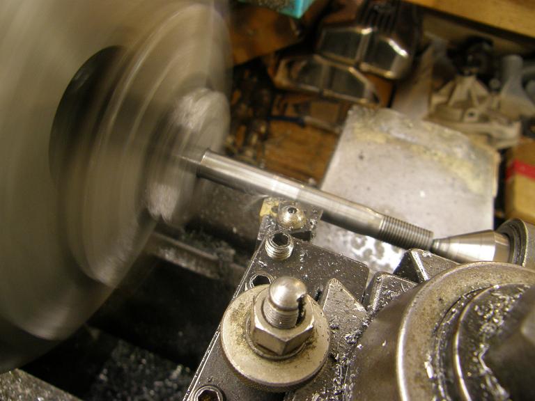
The threading went a lot easier with the original thread available to start the die. After threading the required length of the tie rod, I recut it to get the remaining part of the 2 1/2" removed, and then pulled it out of the lathe to test fit. I threaded on the tie rod end, and it looked like it was a pretty good fit. I did the other side in the same way, then installed both tie rods on the rack with some blue Loctite, and pulled the boots over the tie rods and fixed them in place. After hooking up the tie rod ends and installing them into the spindles, the whole front suspension and steering system was in place, and it was finally looking the way I wanted it to:
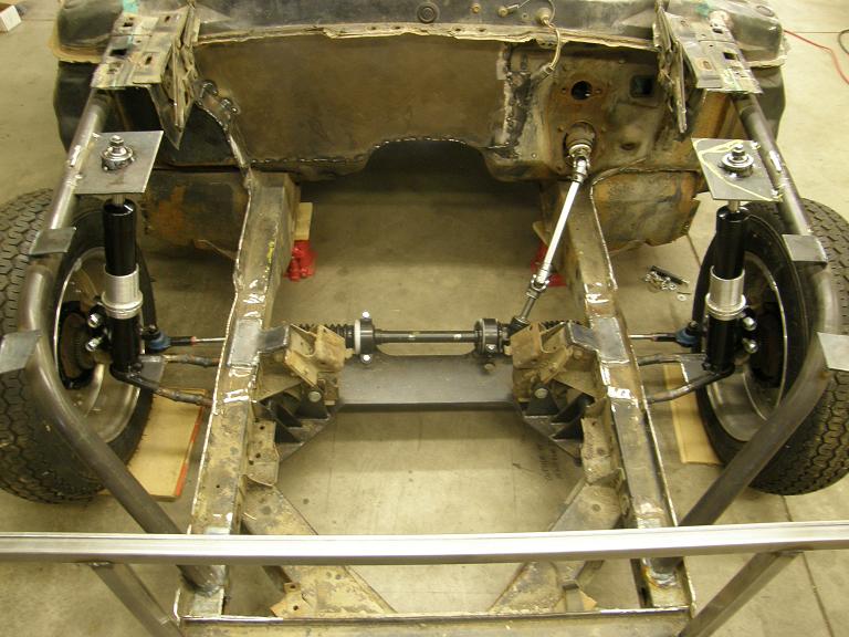
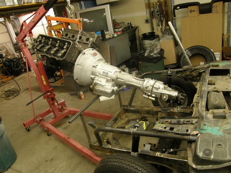
At this point it was only mid afternoon on Sunday, and there was nothing keeping me from dummying in the engine and transmission. This was a big milestone I'd been looking forward to. I had a spare 390 truck block with a pair of cast iron SOHC heads installed that I was going to use for the mock up. I bolted on my ATI Powerglide, then removed the tailshaft housing and installed the Gear Vendors overdrive adapter and the Gear Vendors unit. Hanging from the engine crane this is always quite a sight:
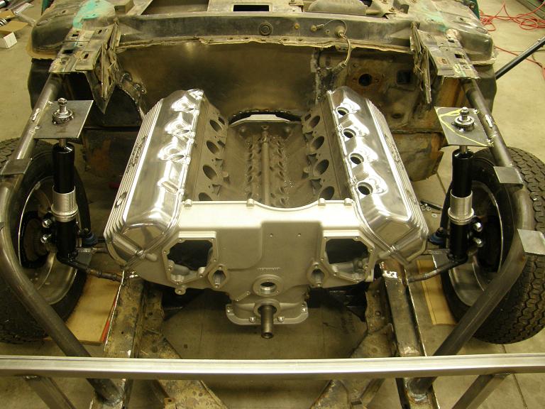
I had to jack the car up a little to get the engine/trans assembly installed, but in short order the engine was resting on the mounts, and a jack was holding up the back of transmission to get everything leveled up. This sight is going to keep me motivated on this project for quite some time:
Before I left the shop today I crawled under the car, got the driveshaft angles set, and measure for the driveshaft. Next week I'll order the driveshaft I need from Mark Williams, and can get to work on tacking up the rear axle housing and all the assorted brackets and braces that have to go there, plus start looking at getting the subframes tied under the car and working out a transmission mount that hopefully will still leave room for the exhaust system to tuck up under the car for maximum ground clearance. Then I can start building the headers. At this point I'm not sure if I'll get done with all this by the end of February or not; we'll have to wait and see how things go over the next few weeks. I'll post another update next weekend.


