After spending the last couple of weeks buried in website creation I finally got back to working on the car this week. I'd been busy with family stuff and book stuff all week, so I didn't get a chance to get back to the car until Saturday morning. First thing I did was to take some measurements off the manual rack so I could modify the bushings I got from Fatman to fit the manual rack. What I had to do turned out to be fairly straightforward, but how to do it was the problem. The rack bushings were made of plastic, and were split in two. Fixturing them so I could machine them in my mill was going to be a problem.
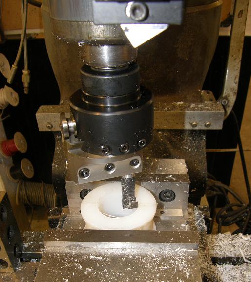
The first thing I had to do was make the hole through the middle of the bushing bigger, then on one side I had to change the profile of the hole from round to square. I started with enlarging the center hole by clamping the bushing halves together in the vise and running my boring bar through to make the hole bigger; see the photo below:
This part went reasonably well, after I got the pressure on the vise dialed in so that it would hold the bushing without distorting it. After I got the hole bored I thought I'd try an end mill to square up the hole in one side, but as soon as I started cutting the plastic bushing flipped out of the vise. I tried it a few more times with the same result, and then tried again with just one half of the bushing in place. This worked better, although when I tightened the half bushing in the vice it's half round shape made it distort. I did manage to get most of the milling done this way, but as I removed more and more material the bushing became less and less rigid, and started flipping out of the vise again. I ended up giving up on the mill in the end and finishing the bushing with a die grinder, but finally got it so it fit reasonably well on the passenger side of the rack.
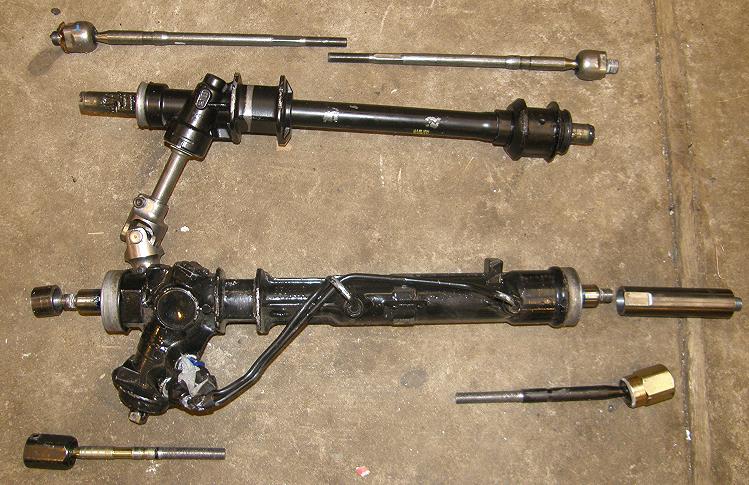
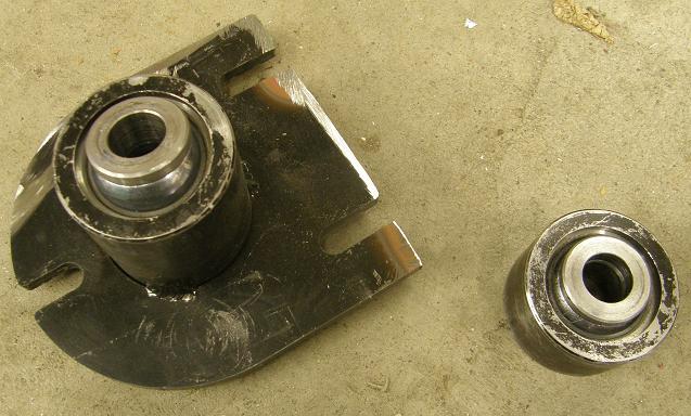
As long as I had the bushing done, and the driver's side bushing was interchangeable with the power rack, I thought I would disassemble the manual rack and then put it in the car, to make sure the steering shaft linkage worked. However, when I disassembled the manual rack, I got another surprise. The tie rod ends for the manual and power racks were not the same. This wouldn't have been a problem, except that the kit used a rack extension on the passenger side, that screws in to where the original tie rod end goes. The passenger side tie rod end then screws into the extension. Obviously, with different size threads this extension would no longer fit. Here's a picture of the racks and their components, disassembled. The power rack is on the bottom:
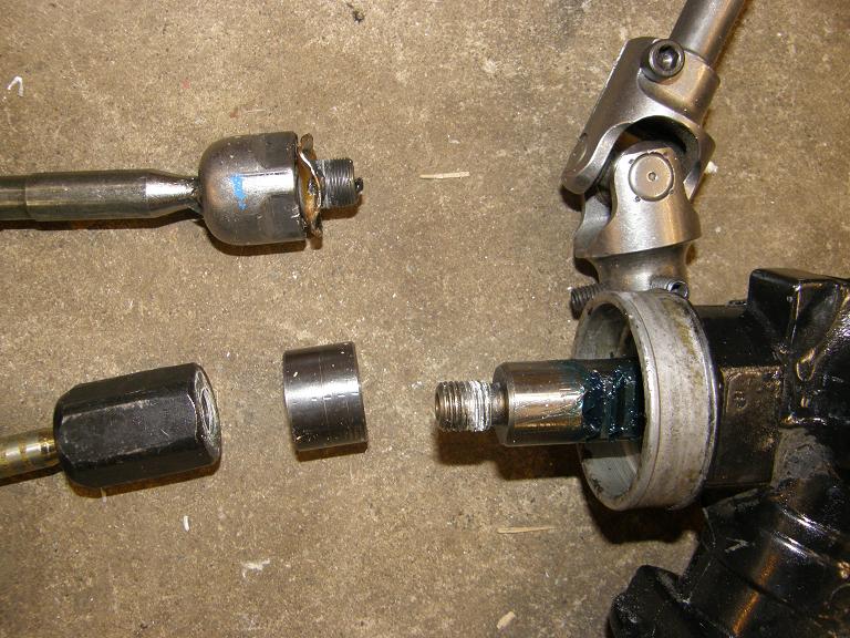
Not only was the thread different, but the "polarity" was different; the power rack's tie rod ends thread onto a stud coming out of the rack, but on the manual rack the stud was was on the tie rod end. Another pic, with the manual rack tie rod end at the top:
Looked like I was going to have to make a new rack extension. I measured the threads on the manual rack tie rod ends, and sure enough they were metric, and an oddball size: 16mm X 1.0mm. I figured I could get a grade 8 bolt in this size, cut off the threads, then just machine a steel sleeve with 16mm X 1.0mm threads in each end. On the computer I went to McMaster Carr, which usually has a pretty good selection of fasteners, but unfortunately the only 16mm bolts they had were 1.5mm or 2.0mm pitch. Same at several other places I tried, so my bolt idea wouldn't work. Back at McMaster Carr at least they had the tap and die sizes I needed, so I ordered those along with a 16mm 4130 steel bar, plus a 1 1/4" 4130 bar for the sleeve. Next weekend I'll have to machine these parts so I can put the rack together.
In the meantime, though, I figured I could tape up the manual rack ends, and get it mounted. This process went along more or less according to plan, and the steering shaft linkage fit the manual rack with no modifications.
Next I decided to tackle the front suspension again. I'd been giving some thought to this during the week, and I wanted to make sure that the extended lower control arms would move the tires where I wanted them before I went forward. So I bolted the driver's side lower control arm in place, then bolted on the spindle and the wheel and tire. I set the car back down at ride height and used my camber gauge to make sure the wheel and tire were perfectly upright. Stepping back and taking a look, the car finally looked normal! Now I could proceed with a revamp of the front suspension, so I removed the front fenders for access and got to work.
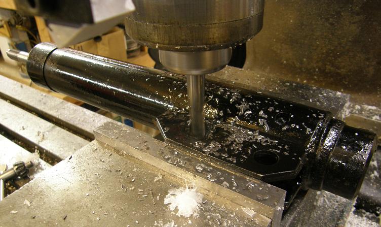
During the week I'd realized that one advantage to lengthening the lower control arms was that the angle of the strut was now going back towards the normal position as designed by the kit. This meant that I might be able to use the struts as is, without the brackets I had built for the Lakewood struts. I bolted one of the Strange struts onto the spindle and it looked very promising. Looking more closely at the strut, it appeared that I could slot the upper bolt hole in the bracket to give me enough room to move the strut where I wanted it. I really wanted to use the Strange struts if possible, because they were adjustable, as opposed to the Lakewood struts which were not. I decided to chuck one of the Strange struts up in the mill and slot the opening to test this idea:
Bolting it back on the car, the extended top hole gave me plenty of room to put the top of the strut where I wanted it next to the front roll cage bar extension, and also appeared to allow plenty of plus and minus camber adjustment. I decided to go forward with this approach.
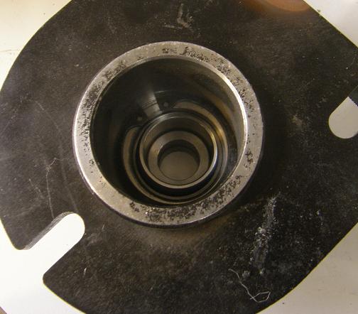
Next I needed to deal with the spring mounts and upper strut mount. The Fatman kit was really designed with road race style handling in mind, and with the included upper strut mount and coil spring mounts there was only about 4" of strut travel. I wanted more than that, to get around 5 inches of wheel drop from the normal ride height to aid in launching at the track. The complete strut travel was 6 1/2", so I had to modify the upper strut mount and spring mount to take advantage of this full travel. The first thing I looked at was the upper strut mount; this contained a bearing in a steel tube, welded onto the adjustment plate from the original kit. The bearing was sunk pretty bar down into the tube:
I couldn't use it buried in there like that, because the distance inside the tube ate up a good inch of the strut travel. I cut the flange off in my bandsaw, and then cut it even closer in the lathe. Here's a before and after picture:
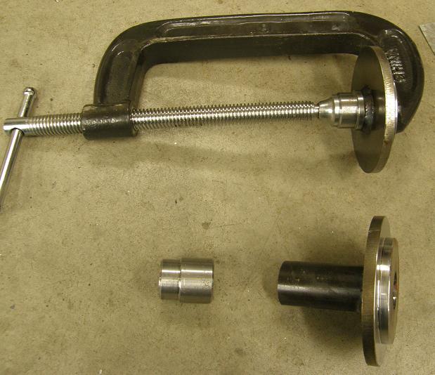
Next I looked at the upper spring mount; this slides over the strut's shaft and supports the top of the coil spring. It had come with the kit with about a 2" tube welded onto it to keep it square with the shaft. Again this was taking up too much of the strut shaft, reducing the potential travel. Some bushings had come with the kit to go into the top bearing that the strut bolted into; I decided to modify the spring mount so that it welded directly onto this bushing. After cutting the tube off the spring mount and shortening the bushing somewhat, I clamped the bushing and the spring mount together for welding. This photo shows the modified assembly in the clamp, and the original parts from the passenger side below:
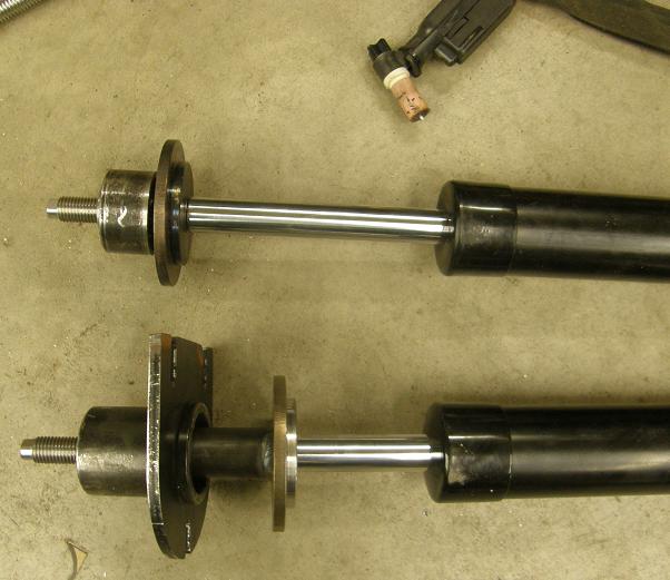
After TIG welding the bushing to the spring mount, I assembled the two struts, one with the modified components and one with the components as received with the kit for this photo:
The only downside I can see from this modification is that I'll probably have to get longer coil springs, but I was planning on getting different springs than the ones that came with the kit anyway, so this is no big deal.
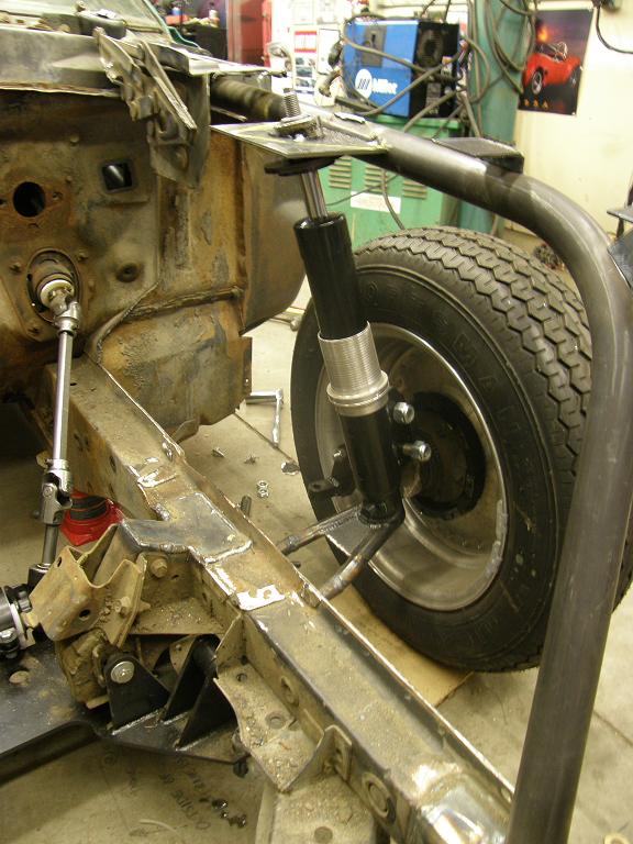
With all the pieces finished up, I assembled the strut and components on the spindle, and built a plate to weld to the forward roll cage extension bar , and also to the steel tube around the top strut bearing. I cut the hole in the plate for the tube on the mill, and touched it up with a die grinder to allow the tube to come through at a little bit of an angle, as required. Finally, with my son Max helping me by holding the plate in position, I tacked it to the front roll cage bar, and also to the bearing tube in a few spots. The driver's side front suspension now looked like this:
From here I have to cut the tacks to the forward roll cage extension bar, remove the top strut bearing from the tube so I don't fry it by welding, and weld all the way around the tube and plate junction. Then I have to trim the plate to the shape I want, reweld the plate to the forward roll cage extension bar, and come up with some support brackets to keep the plate stable and strong so that it can take the force of coming down from all those wheelies!
I'll work on that next weekend, and now that I have the plan, hopefully I can get the passenger side done, and also finish up the modifications to the steering rack so that I can test out the steering. Shortly afterwards I should be able to pop in the engine and trans, and get the rear end brackets tacked in place once the driveshaft angles are set. I'm still hoping to be done with all the chassis work by the end of February; we will see. More next week - Jay


