Author Topic: 545" High Riser Build  (Read 184264 times)

0 Members and 1 Guest are viewing this topic.

cammerfe

  • Hero Member
  • *****
  • Posts: 1659
    • View Profile
Re: 545" High Riser Build
« Reply #120 on: January 09, 2012, 02:29:54 PM »
Since I run a stand-alone methanol injection system to act both as the fuel with my 'spray' system and as a chemical intercooler to augment turbo boost on my Land Speed car, I can tell you that the use of methanol will open up a whole new world of experimentation/tuning when you get to that point. Methanol is VERY forgiving in terms of air/fuel ratios, clear to the point of having to be careful of hydraulic lock. When you have other things in place and start experimenting with methanol you'll wonder why you took so long to get there!

KS

cdmbill2

  • Jr. Member
  • **
  • Posts: 87
    • View Profile
Re: 545" High Riser Build
« Reply #121 on: January 09, 2012, 06:14:28 PM »
Jay: I bought an MS3X unit before DW11 and we used it with the eight AFR setup, but we didn't have time set up and transfer the tune. I had built the harnesses etc. buit time got thight. That video dyno session was four days before I loaded up to go to Kansas, not quite as bad as your thrash, but close.

The MS# will of course handle individual cylinder fuel and spark as well as a bunch more datalog capability.

TimeWarpF100

  • Hero Member
  • *****
  • Posts: 683
    • View Profile
Re: 545" High Riser Build
« Reply #122 on: January 09, 2012, 10:01:54 PM »
I have been keeping an eye on this build since the beginning but had not posted here before. Simply mind boggling work. Love it!

jayb

  • Administrator
  • Hero Member
  • *****
  • Posts: 7405
    • View Profile
    • FE Power
Re: 545" High Riser Build
« Reply #123 on: January 10, 2012, 08:17:52 AM »
Jay: I bought an MS3X unit before DW11 and we used it with the eight AFR setup, but we didn't have time set up and transfer the tune. I had built the harnesses etc. buit time got thight. That video dyno session was four days before I loaded up to go to Kansas, not quite as bad as your thrash, but close.

The MS# will of course handle individual cylinder fuel and spark as well as a bunch more datalog capability.

Hmmmm, I was not aware of the MS3X.  I will look into that controller.  Thanks for the heads up, Bill!
Jay Brown
- 1969 Mach 1, Drag Week 2005 Winner NA/BB, 511" FE (10.60s @ 129); Drag Week 2007 Runner-Up PA/BB, 490" Supercharged FE (9.35 @ 151)
- 1964 Ford Galaxie, Drag Week 2009 Winner Modified NA (9.50s @ 143), 585" SOHC
- 1969 Shelby Clone, Drag Week 2015 Winner Modified NA (Average 8.98 @ 149), 585" SOHC


cdmbill2

  • Jr. Member
  • **
  • Posts: 87
    • View Profile
Re: 545" High Riser Build
« Reply #124 on: January 10, 2012, 02:49:55 PM »
Doc (Seered) went to that for DW 2011 and DG has a very good handle on it now. Its one of Matt Cramer's products. Not the same source as the EMS-Pro, that one is coming I'm told.

dieselgeek

  • Newbie
  • *
  • Posts: 23
    • View Profile
Re: 545" High Riser Build
« Reply #125 on: January 10, 2012, 05:39:36 PM »
Bill's correct, I am a lot more comfortable with MS3X now that we finished EMC, Doc's car, etc.

Jay you'll like it because there are a ton of other inputs you can log.  On Doc's car we're picking up Oil Temp, Oil Pressure, Fuel Pressure, Vehicle Speed on top of the usual Coolant temp, Air Temp, MAP, TPS, etc.  It has an SD card for datalogging, there were a few bugs with the logging back in October but it appears those bugs are worked out.  He has a switch on the dash to toggle between his E85 tune (track) and gasoline tune (street/highway).  Doc is happy with how it performed.

DIYAutotune.com supplies them.

As usual, Jay, let me know when I can schedule a visit so we can set it up and have some fun tuning 8 1-cylinder engines on your dyno :-)

-Scott

machoneman

  • Hero Member
  • *****
  • Posts: 3853
    • View Profile
Re: 545" High Riser Build
« Reply #126 on: January 12, 2012, 09:47:28 AM »
Hey Bill, do you have some pics of your LSR car and engine available? Or, maybe a link to a site where we could gaze on them?
Bob Maag

cammerfe

  • Hero Member
  • *****
  • Posts: 1659
    • View Profile
Re: 545" High Riser Build
« Reply #127 on: January 12, 2012, 06:38:51 PM »
If that question is addressed to me, you can get a few rudimentary pictures by going to LVC Forum and looking in the sub-section labeled as 'LS High Performance.' There's a running commentary of my slow efforts to go from E Fuel Competition Coupe/sedan to E Blown Fuel Competition Coupe/sedan. There are some photos along about the fifteenth or sixteenth post. The record can be viewed at the ECTA website. Perhaps a whole new ball game now that it'll no longer be necessary to tow clear to North Carolina and instead just go to the general Cleveland, Ohio area.

KS

machoneman

  • Hero Member
  • *****
  • Posts: 3853
    • View Profile
Re: 545" High Riser Build
« Reply #128 on: January 12, 2012, 06:56:46 PM »
Thanks, I'll do that CammerFE (sorry, I mistakenly said Bill).
Bob Maag

Joe-jdc

  • Guest
Re: 545" High Riser Build
« Reply #129 on: January 12, 2012, 08:53:47 PM »
Well, Jay, I was hoping you would be the first to get a FE to break the 1000 HP with a verifiable dyno pull, but apparently not----SO how about the first FE to break 1100 NA?  DOABLE???  :-X  Joe-JDC

jayb

  • Administrator
  • Hero Member
  • *****
  • Posts: 7405
    • View Profile
    • FE Power
Re: 545" High Riser Build
« Reply #130 on: January 12, 2012, 11:18:26 PM »
I think it's do-able with a cammer, but not with a wedge.  For what it's worth, I try to design all my engines so they will run on pump gas around town.  As a result I'm giving away some potential power from compression, and also not being on the ragged edge on the cam. 

My target is actually 1000 HP on pump gas.  THAT would be cool...
Jay Brown
- 1969 Mach 1, Drag Week 2005 Winner NA/BB, 511" FE (10.60s @ 129); Drag Week 2007 Runner-Up PA/BB, 490" Supercharged FE (9.35 @ 151)
- 1964 Ford Galaxie, Drag Week 2009 Winner Modified NA (9.50s @ 143), 585" SOHC
- 1969 Shelby Clone, Drag Week 2015 Winner Modified NA (Average 8.98 @ 149), 585" SOHC


jayb

  • Administrator
  • Hero Member
  • *****
  • Posts: 7405
    • View Profile
    • FE Power
Re: 545" High Riser Build
« Reply #131 on: January 23, 2012, 12:52:44 AM »
Got back on the high riser project this week, and managed to get most of the tough stuff done on the intake manifold.  I still have a lot of work to do on it, but the initial welding is complete, and thanks to my jig and carefully machined parts, it seems to have weathered this part of the build just fine, with no extreme warping to worry about. 

During the evenings this week I spent some time trimming up the runner assemblies in the mill to make them all identical, so that I would have minimal problems with fit.  I also bolted the port plates and the intake manifold base plates to the heads, and used some sand rolls to remove the CNC tooling marks inside the runners, and smooth everything out so they lined up perfectly with the ports in the heads.  It was cool to be able to do this; when I got done it looked like the port runners were a single piece, except where the gasket was between the port plates and the heads. 

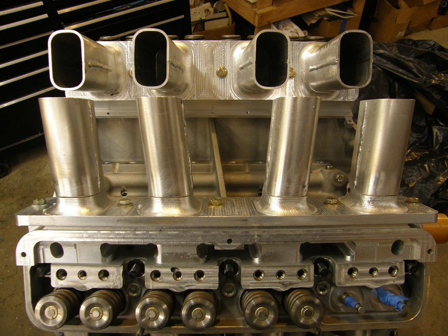
Friday night with a full weekend in front of me I spent the evening tacking the runners to the intake manifold base plates.  I wanted to be able to move them around a little if necessary, so I didn't weld them completely, just ran about a 3/4" long bead along the bottom of the runner to hold it securely in place for fitting the plenum plates.  Then I bolted the heads, port plates, and manifold base plates to the engine, with the head gaskets installed but without the intake manifold gaskets.  My thinking here was that I wanted to make the intake manifold wider than necessary, to give me some room to machine the manifold base plates in case they warped during the welding operation and needed to be planed.  Here's a couple photos of the engine with all this stuff installed:


Saturday I started by taking my two plenum plates, which I had previously welded together into a V, and tried to fit them on the runners.  They were close, but sat up about 1/8" too high.  If you look at the previous photos I posted you can see that the plenum plates have the runner entrance machined into them, with about 1/4" of each runner extending out of the plates, to make welding to the formed runners easier.  I took the welded plenum plate and stuck it in the mill, and cut .125" off the extensions on the plates.  Back on the engine the plenum plates now fit almost perfectly.

I weighted down the plenum plates on the runners to keep them stable, and started welding the runners to the plenum plates.  After getting all eight runners tacked, I continued welding as far around the runners as possible, both up at the plenum plates and down at the manifold base plate on each side.  When I finally got done, about 2/3 of the welding was finished.

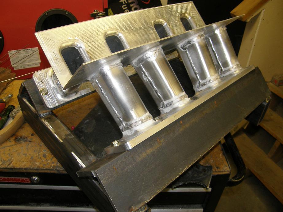
My original plan had been to unbolt the manifold from the port plates at this point, and use it as a pattern for a jig to be used for welding the remaining seams.  I had a brief urge to just tear the manifold off the engine and finish welding it on the bench, without the benefit of the jigs, but after thinking it over for a little while, and remembering how much time I had into the manifold port plates, runners and plenum plates, I decided I'd better not chance it.  So, I grabbed the 4" angle iron and 2X3 square steel tubing I'd purchased for the jig and set about building it.  After cutting the steel to length I put the 4" angle iron in the CNC machine and drilled the holes to match the manifold base plates, then tapped the holes for 3/8-16 bolts.  Finally I bolted the partially welded intake to the angle iron, set it on the square steel tubing, and welded the angle iron to the square steel.  Here's a photo of the partially welded intake on the jig:


Now that the jig was done I was able to complete welding on the intake.  I flipped the jig over to get access to all the runners for welding.  Just like on my SOHC sheet metal intake, this gave me excellent access for welding, and it was not problem to get the manifold welded up.

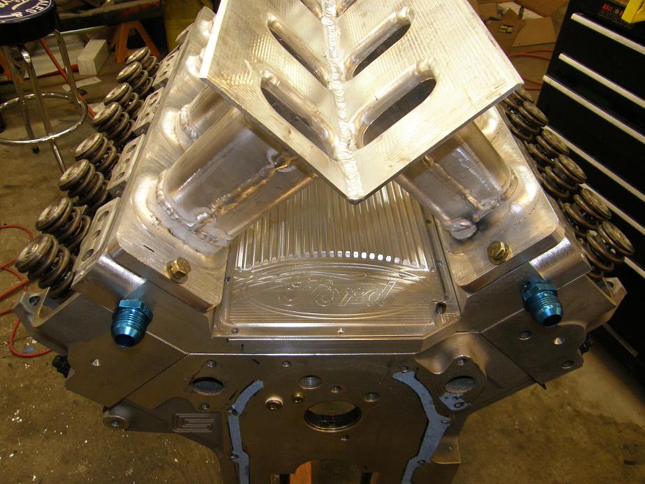
Over the course of the last few weeks I've been rethinking the oiling system on this engine.  I had planned to use a stock type oil pump, and drive it with a "half distributor", which would be a partial distributor shaft that bolted into the distributor's location, and connected the cam gear on the cam with the oil pump drive shaft.  One problem with this design was that where the half distributor (or a full distributor for that matter) came through the intake manifold, there was always a vacuum leak when I tried to run a crankcase vacuum pump.  Bill Fowler had been  telling me about his Peterson external oil pump, so I decided to look into one of those.  I liked what I found out; the pump sucked out from a line at the bottom of the oil pan, but also could be ordered with some scavenge stages that essentially created crankcase vacuum.  Using this setup I could eliminate the half distributor and the external vacuum pump, and also the potential vacuum leak at the half distributor location in the manifold.  I made the decision to go forward with this setup.  As a result of that, I decided to machine a new valley cover plate, one without the distributor hole, to completely seal up that potential leak.    Here's a photo of the new valley cover plate installed on the engine, with the port plates:


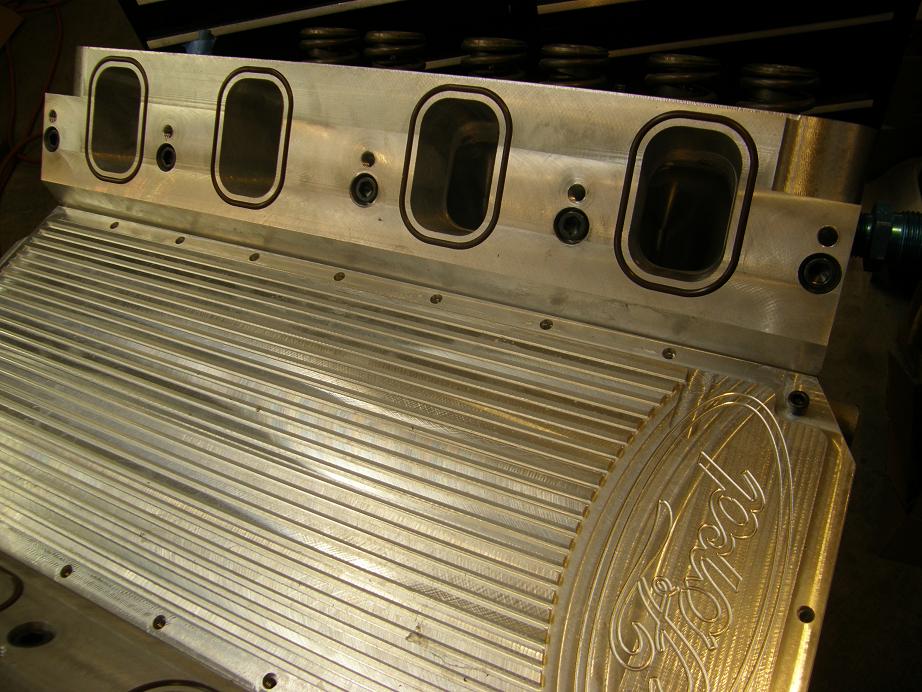
In the photo above you can see that with the extra room created by the lack of the distributor hole I was able to make the Ford logo bigger, which I thought was pretty cool.  Also you can see the Viton O-rings installed on the port plate, in preparation for installation of the manifold.

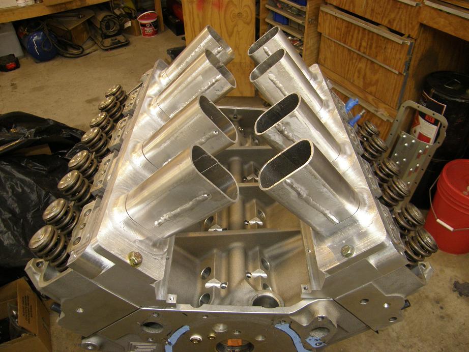
Finally, after the manifold cooled down today I bolted it back onto the engine to see how it fit after the final welding.  It appeared that the mating surfaces were still pretty flat, but that the entire manifold had shrunk just a little bit.  The ports and bolts still lined up perfectly though, and I still had the port plates installed without the .060" thick intake gaskets.  So I think that once they are installed, the manifold may fit pretty well as is.  Worst case it looks like I might have to take .010" or .020" off the mating surfaces.  Here's a photo of the manifold installed on the engine:


Next up is the finish porting work inside the runners where they meet the plenum plates and port plates, and then installing the injector bungs and welding them and the fuel rail brackets in place.  Then I'll be able to finish the plenum of the intake and start thinking about the top plate to mount the Dominator throttle bodies.  I'm looking forward to seeing the whole thing put together!  I'll post more photos as I make progress.
Jay Brown
- 1969 Mach 1, Drag Week 2005 Winner NA/BB, 511" FE (10.60s @ 129); Drag Week 2007 Runner-Up PA/BB, 490" Supercharged FE (9.35 @ 151)
- 1964 Ford Galaxie, Drag Week 2009 Winner Modified NA (9.50s @ 143), 585" SOHC
- 1969 Shelby Clone, Drag Week 2015 Winner Modified NA (Average 8.98 @ 149), 585" SOHC


rcodecj

  • Sr. Member
  • ****
  • Posts: 474
    • View Profile
Re: 545" High Riser Build
« Reply #132 on: January 23, 2012, 01:08:36 PM »
As I started reading your post, I thought that if it were me I would make the manifold base plates a little wider to allow you to machine it flat to compensate for welding warpage.
I then read on and saw that you thought the same thing.
It looks like it was a very good idea.  :D
I can imagine that aluminum would want to move around quite a bit as even thin steel will warp/move when welded.
I have never heard of the Peterson pump before this, that is quite the deal to be able to eliminate the vacuum pump.
Looks like it's really coming together!  8)

jayb

  • Administrator
  • Hero Member
  • *****
  • Posts: 7405
    • View Profile
    • FE Power
Re: 545" High Riser Build
« Reply #133 on: February 19, 2012, 11:05:25 PM »
After being out of the country for a couple of weekends, and then spending last weekend recuperating from the jet lag, it felt good to get back out to the shop and get some work accomplished this weekend.  Picking up where I'd left off on the sheet metal intake manifold, I decided the next step was to get the injector bungs welded into the runners.  First I cut some 3/4" aluminum bar into 1.75" lengths for the bungs, and then drilled them in the lathe with a 17/32 bit to fit the injectors.  Next, I fixtured the upper intake manifold in the CNC machine and plunged a hole into each runner with a 1/2" end mill, then enlarged it to 3/4".  Using the same runner to runner dimensions that I'd used to bore the runner holes, I put the holes for the injectors into the fuel rails.  There's a special tool required for this, available from Kinsler fuel injection, so I had bought the tool and the blank fuel rail from them before going off to Europe.  After the fuel rails had the matching holes bored in them, I used a couple of dummy aluminum fuel injectors that I had built for the previous sheet metal intake and fixtured the fuel rails and injector bungs onto the manifold.  This was kind of a tedious process, and it was problematic because the injector bungs kept wanting to slide down through the holes in the manifold, but after persevering for a while I finally got all eight injector bungs tacked in place.  After finish welding, the upper manifold now looked like this:


At this point I removed the upper manifold from the jig and spent a few hours with the die grinder smoothing out the internal passages where the runners met the plenum plates and port plates, and also where the injector bungs protruded into the runners.  This particular job is the worst part of the whole process if you ask me, because it seems to go so slow, but finally I got the runners and the bottom of the plenum looking like I wanted them to look.  Bolting the manifold back on the jig, I cut the pieces required for the remainder of the plenum and tacked them together:


Finally I took some 1/2" square aluminum bar and made the side rails for the top of the intake, and tacked them in place.  Once this was finished up, I just had to fry it all together.  My aluminum welding is still suspect, but I felt pretty good about welding a leak free plenum because the beads seemed to flow into the aluminum pretty nicely during this process.  I welded all around the outside of the intake, and also on the inside, sealing up any crevices where fuel might puddle and cause driveability or inconsistent mixture issues.  Overall I think it came out reasonably well, given my limited welding skills:


Finally, I put the injectors and fuel rails in place on the manifold, and cut four small pieces of 1/2" square aluminum bar to use for attaching the fuel rail to the manifold.  After welding these in place, I took the manifold off the fixture and put it on the engine, along with all the other sheet metal intake pieces I needed for this setup:


The only thing left to do on the manifold upper is to machine the top mounting surface flat, and to cut about .030" off each manifold mating surface so it will fit properly on the port plates.  After this is completed, I have to machine a top plate for the manifold to mount the two throttle bodies, and then I am pretty much done with this intake.  With luck I'll be finished up sometime in the next week or so.  I'll post some pictures of the finished product when I get done.


Jay Brown
- 1969 Mach 1, Drag Week 2005 Winner NA/BB, 511" FE (10.60s @ 129); Drag Week 2007 Runner-Up PA/BB, 490" Supercharged FE (9.35 @ 151)
- 1964 Ford Galaxie, Drag Week 2009 Winner Modified NA (9.50s @ 143), 585" SOHC
- 1969 Shelby Clone, Drag Week 2015 Winner Modified NA (Average 8.98 @ 149), 585" SOHC


Drew Pojedinec

  • Hero Member
  • *****
  • Posts: 2116
    • View Profile
Re: 545" High Riser Build
« Reply #134 on: February 20, 2012, 07:46:42 AM »
Jay,
For all of us that have zero interest whatsoever in SOHC Fe's, I'd like to say thank you for this thread.

It is awesome and something that many of us can aspire to.