On my 390 stroker project in the Member Projects section I had been looking to use a main stud girdle, but couldn't find one available at the time I wanted to do it, so I went with crossbolted main caps instead. They were expensive, and a real pain to install. I wanted to try installing a girdle as a comparison, and it turned out that one of my cylinder head customers was going to use a 390 block and put a girdle on it. I offered to install it for him at no cost because I wanted to see how difficult it would be. He was able to find a girdle like the one I wanted to use, so last week he drove up to my place and dropped off the block and the girdle and hardware. This week during a break in the action I got his block on the CNC machine and started the installation.
My plan was to precisely indicate the height location of the five main cap registers in the block, then shim up the block to make them as level as possible. From there I wanted to cut a few thousandths off the pan rail, in order to make sure that it was square with the main cap registers before machining the caps and bolting on the girdle. I had been told that the oil pan rail would not necessarily be square with the main cap registers, and in order to make the girdle a nice fit I wanted to make sure that it was.
By the way, the directions that came with the girdle didn't suggest anything like this, basically saying to use the oil pan rail as it was. This didn't sound right to me, since if the pan rail turned out not to be square with the main cap registers the girdle would have to deform to fit.
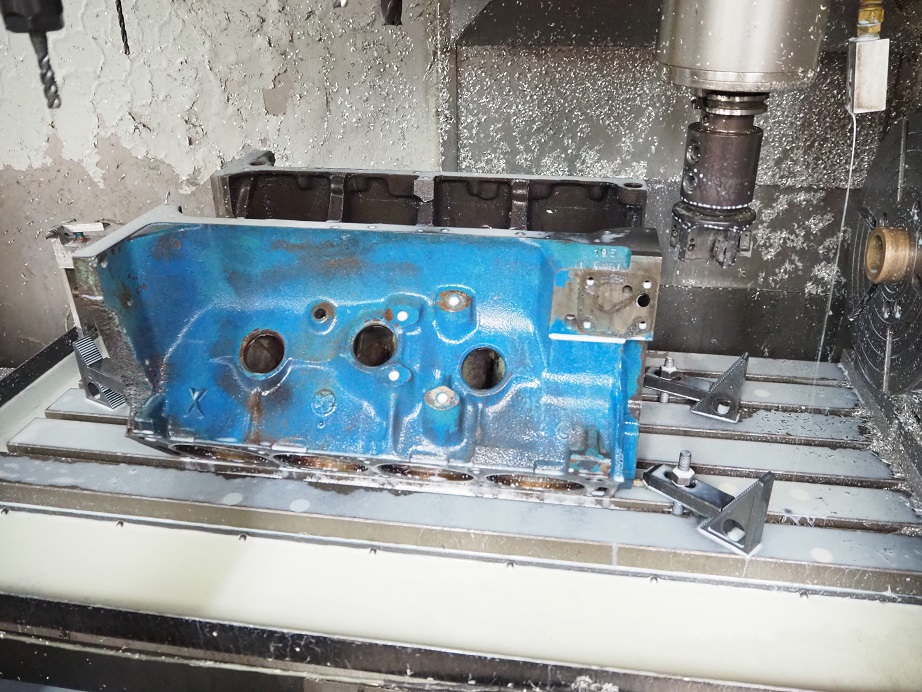
Anyway, I set the block up on the CNC table, resting with the main cap registers facing up and roughly aligned square with the table, clamped it in place, and started measuring the height of the main cap registers. This was done with an arbitrary Z axis setting; all I was interested in was how the main register heights compared with each other. I figured that they would all be very close, and I was surprised at how close they actually were. On the right side of the block, they were all within 0.002" of each other, and the left side was only a little worse:
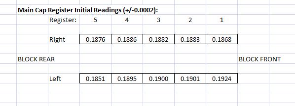
On average the left side of the block looked just a couple thousandths higher than the right side of the block, which I thought was pretty good given that the block was sitting upside down, and relying on the squareness of the end rails relative to the main cap registers. In order to make the main cap registers as level as possible, I used some .004" shim stock under the right side of the block's end rails on each end. I remeasured and got the following results:
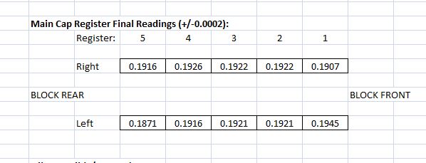
This brought the height of the #2 and #3 main cap registers just about the same, and #4 was only off by a thousandth. #5 was off by almost 0.005", but that wasn't a concern because the girdle doesn't tie into the #5 main cap. The left side of #1 was about 0.004" higher than the right side, and I figured I could compensate for that with the spacers.
Now that the main registers were as squared up as I could make them, I measured the height of the oil pan rail in the four corners of the block:
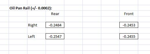
These results were not nearly as bad as I had been led to believe; worst case variation was only about 0.010", and since the distances across the block were much greater than the distances across the main cap registers, it really wasn't that bad. Nevertheless, I set up my 3" facing mill and took about 0.012" off the oil pan rail, to square it up with the main cap registers:
This whole process, from getting the block fixtured on the CNC machine, to cutting the pain rail, took about an hour and half. No big deal.
Next I took caps 1 through 4 and put them into the vise on my smaller CNC machine. I indicated off the ways of the vise in the Z axis, and then indicated on each main cap bolt hole to find it's center. Then I wrote a short CNC program to spot face the bolt holes in the top of the caps, to make them all exactly the same height. I tried to go to a 2.5" height from the bottom of the caps up to the spot face, but it turned out that one of the caps was a little lower than that, so I went down to a height of 2.475" to get all the spot faces on the caps exactly the same height from the bottom of the caps. It took about an hour to machine the caps.
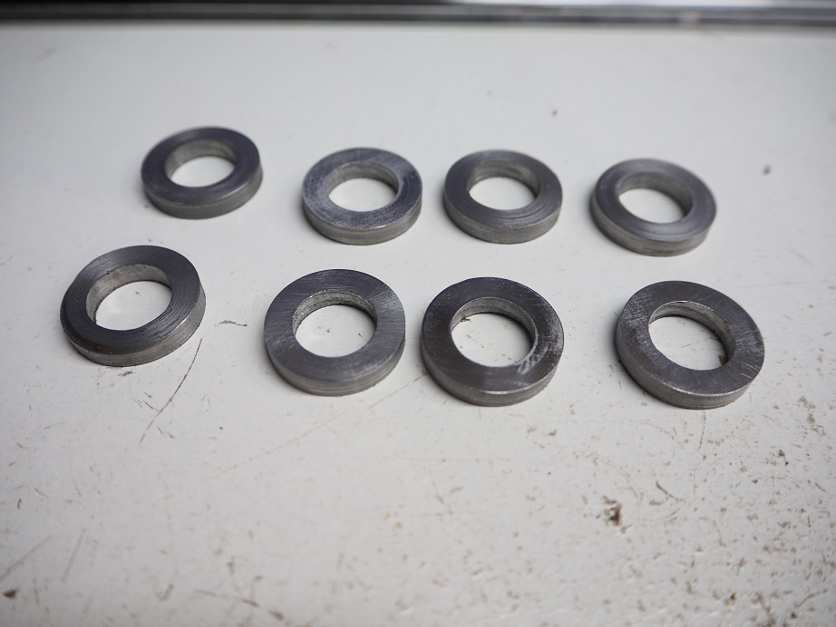
Another quick aside is that the manufacturer provides a spacer between the cap and the girdle that is a single piece strap for each cap, with two holes in it. They tell you to bolt the girdle on the block, then measure the distance from the main cap registers up to the girdle, subtract the thickness of the strap, and machine the whole top of the cap to get the height to that dimension. I also did not like this idea, it seemed to me that getting a precise measurement of this distance would be problematic, and also machining any more off the cap than necessary would limit the strength of the cap. So I elected not to use the straps, and decided to make up some donut spacers instead.
With the block still fixtured on the CNC machine, I measured the distance between the main cap registers and the oil pan rail, subtracted the 2.475" distance from the cap base to the spot face, and found that I needed spacers about 0.182" thick. Due to slight variations in the height of the registers, I ended up machining spacers of slightly different thicknesses, ranging from 0.180" to 0.184". This was the most time consuming part of the project, and hindsight being 20/20, I can think of a much easier way to do this; more on that shortly. It took me about 3 hours to get these 8 donut spacers machined:
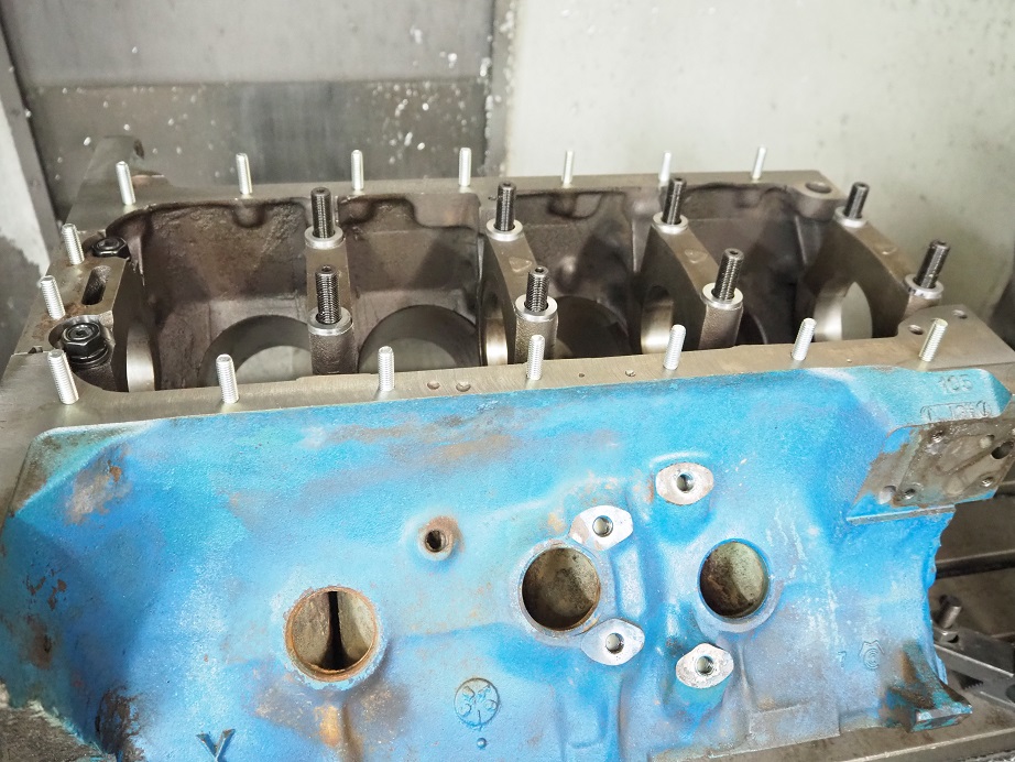
From there I assembled the main studs in the block. The stud kit included two studs that were shorter than the other eight, for use in the #5 cap, but actually they were still too long to be used, and even with the presence of the girdle they would stick up above the oil pan rail. The instructions said they "may" need to be cut to fit

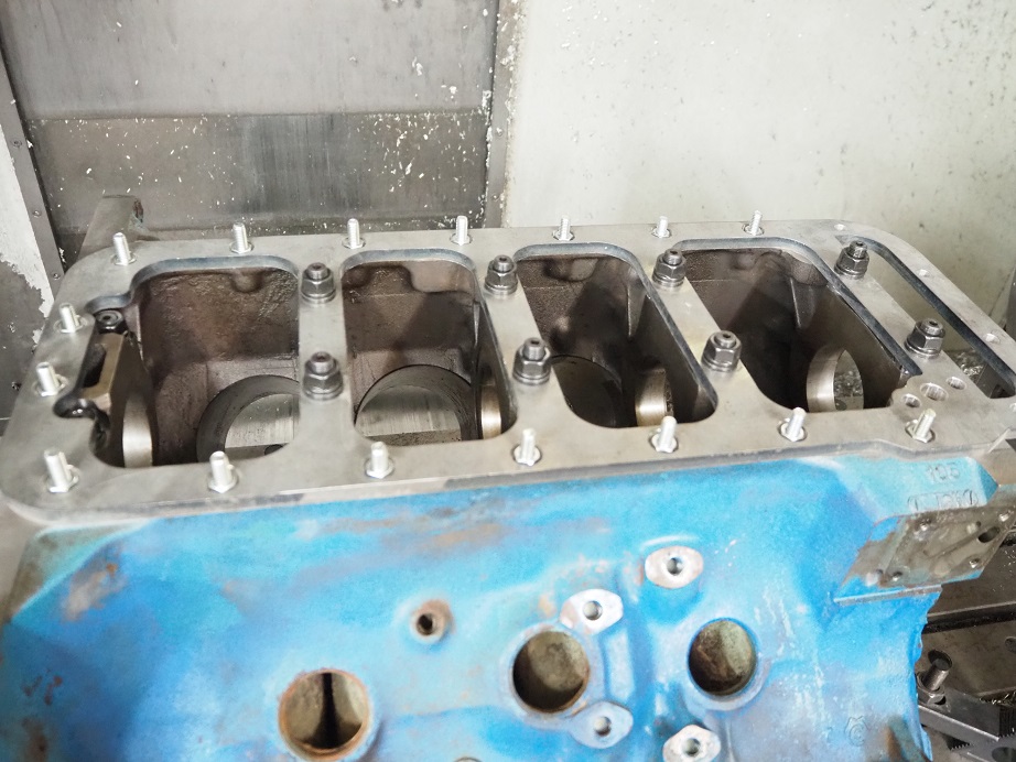
Anyway, I had known about this issue and had the block owner buy some special, shorter studs for the #5 cap. To make the stud washers and nuts fit, I also counterbored the #5 cap 0.275". I installed the studs, the caps, and the spacers in the correct location to make them all the same height, then finally I installed the oil pan studs that came with the kit; here's a picture of how the block looked at this point:
The girdle fit nicely down on the block, and in fact it could be wiggled around a little; probably the holes for the studs are slightly oversize. The main stud washers and nuts were installed next. The kit comes with some thin nuts that fit into the counterbored areas of the girdle. I found that the counterbored holes were too small for my 3/8 drive 1/2" socket to fit, so I couldn't use that to tighten the nuts; I ended up going to a 1/4 drive ratchet and socket to get them tight.
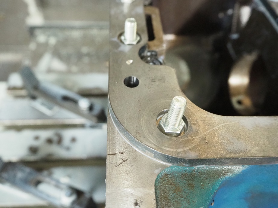
The last thing I did was to machine a couple of precision holes for some 3/8" diameter steel pins, in order to positively fixture the girdle on the pain rail. I was uncomfortable with the fact that the girdle could slide around some when it was placed over the studs, and despite being clamped down, I wanted a more positive location for it. So I machined two holes through the girdle and into the block, and will install some steel pins to lock it into a fixed position. Here's a photo of one of the holes:
Having installed one of these now, I can say by comparison it is a much easier installation than the cross bolted caps. With the crossbolted caps, the block has to be perfectly aligned in the X axis of the mill, and also perfectly machined to make the caps fit properly. Then, the block has to be set up on the machine rotated 90 degrees along the X axis to drill the holes for the cross bolts on one side, then it has to be set up at -90 degrees to drill the crossbolt holes on the other side. This is a ton of setup work, and horsing the block around to these different positions, and then fixturing it in those positions, is very time consuming. Not to mention tapping the cross bolt holes in the caps.
Despite being more expensive by around $200, and requiring much more expensive machine work, the cross bolted caps are probably more rigid than the standard caps using a girdle. My take on this though is that given the cylinder wall and main web thickness of a 390, the cross bolted caps may be overkill. I'm pretty sure that the girdle will make the block able to withstand 650-700 HP, and it probably wouldn't be a good idea to go beyond that with a 390 block anyway.
One issue with the girdle that I don't like is that the spacers have to be kept in the same position, in order to maintain minimum stress on the girdle. Since they are slightly different thicknesses, if you mix them up you may impart a twist into the girdle when it is assembled. I thought I was going to be able to address this by just stamping or scribing each spacer with it's position, but that didn't turn out to be practical; the steel was not easy to scribe, and when I tested stamping an extra spacer, it raised the material around the stamp mark and changed the thickness. So the spacers need to be carefully marked when removed, and then replaced in the same spot.
Another concern with the girdle is that if you want to run a windage tray, it is going to be spaced 3/8" farther from the crank, making it a little less effective.
Speaking of the spacers, if I was going to do this project again, I'd take advantage of the precise ring shims available from McMaster Carr. For example, they have a 0.188" thick spacer with a thickness tolerance of +/- 0.007", and they have .001" and .002" thick ring spacers, with thickness tolerances of much less than .001". Having a selection of those on hand, and cutting the main cap spot faces just a little deeper than I did, would allow these off the shelf shims to be used as the spacers, taking the majority of time out of this project. If I ever do another one of these, that's what I'll do.
One last comment is that after this work is done, the block should be align honed, if it hasn't been already. Sometimes the machine shop will take a few thousandths off the bottom of the caps to align hone the main saddle. If that happens, then some of those really small shims mentioned previously will have to be added to the shims that are already in place between the girdle and the caps. For example, if the shop takes .002" off the bottom of each cap, then a 0.002" shim should be installed with each spacer. But again, since those shims are readily available, no big deal.
I hope this quick tutorial will help if you are considering a girdle for your engine. Anybody with a vertical mill can do this work, although it is a little easier with CNC, and it seems like a good upgrade for a 390 or 428 block that is headed for serious horsepower.


