Author Topic: 390 Stroker for FE Power Cylinder Heads  (Read 5360 times)

0 Members and 1 Guest are viewing this topic.

jayb

  • Administrator
  • Hero Member
  • *****
  • Posts: 7405
    • View Profile
    • FE Power
390 Stroker for FE Power Cylinder Heads
« on: June 24, 2021, 04:57:12 PM »
One of the things I've wanted to do with my cylinder head package is to put it on a fairly standard 390 stroker engine, and see how it performed.  I've had a little break in the action on the head project, because the aluminum foundry is really backed up and despite ordering castings for the intake adapters and heads in March and April, they have still not been poured, so I decided to get a head start on this project.  I have two 390 blocks here that I could choose from, so I decided to sonic test them and pick the best one.

One of the blocks is already .040" over; this is the block that was the basis of my 390 stroker engine, featured in my book.  I had set this engine on the stand and forgotten about it for the last 10 years, so a few days ago I pulled it all apart so I could check it.  Everything looked very good, which was encouraging after all the dyno abuse that this block saw.  But when I sonic tested it, there were a few holes that looked a little thin to me.  The sonic test results are below:


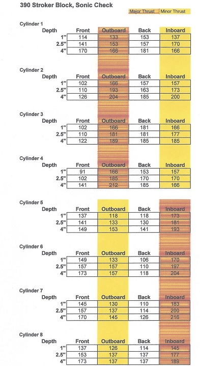
In particular, the front side of cylinders 2 through 4, and the back side of cylinders 6 and 7, looked a little thin.  I was going to bore this block another .020", and my arbitrary requirements for minimum cylinder wall thickness is 0.100" after boring for non-thrust surfaces, and 0.125" after boring for thrust surfaces, hopefully with more thickness on the major thrust side (shown in red in the picture) than on the minor thrust side (shown in yellow).  Several cylinders on this block weren't going to meet these requirements.  Now, of course this block took a bunch of abuse at 500+ HP on my dyno, and as-is cylinder 4 is below my requirements, and there weren't any problems, so maybe I shouldn't be too concerned.  But I decided to check the other block out and see if it looked better.

Turned out it did; the sonic check data for that block is below:


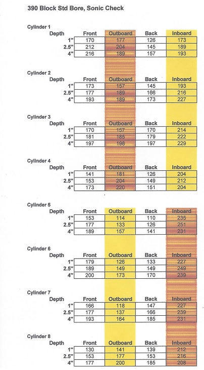
This block is currently standard bore, which helps of course, and the areas of concern were the minor thrust sides on cylinders 5, 6, and 7.  Again I was figuring to bore this block .020" (0.010" on each side), and I'd be below my arbitrary requirements on the minor thrust side of these cylinders.  However, I'm a big believer in sleeves, since they are actually better material than the block material itself, so I think I will sleeve 5 and 7, and leave 6 as-is, to make this block as robust as possible. 

Since I was going to abuse this engine somewhat, I had previously decided to run a girdle.  I had never used one and wanted to try one out, and there had been one appearing on ebay that I thought looked pretty good.  I was planning to pin the rail of the girdle to the pan rail, so that it couldn't move, and then machine some precision spacers to go between the girdle and the main caps.  I was going to bolt it all together, take the block in for an align-hone, and then if the caps had to be cut a few thousandths, compensate with some shim stock between the caps and the girdle.

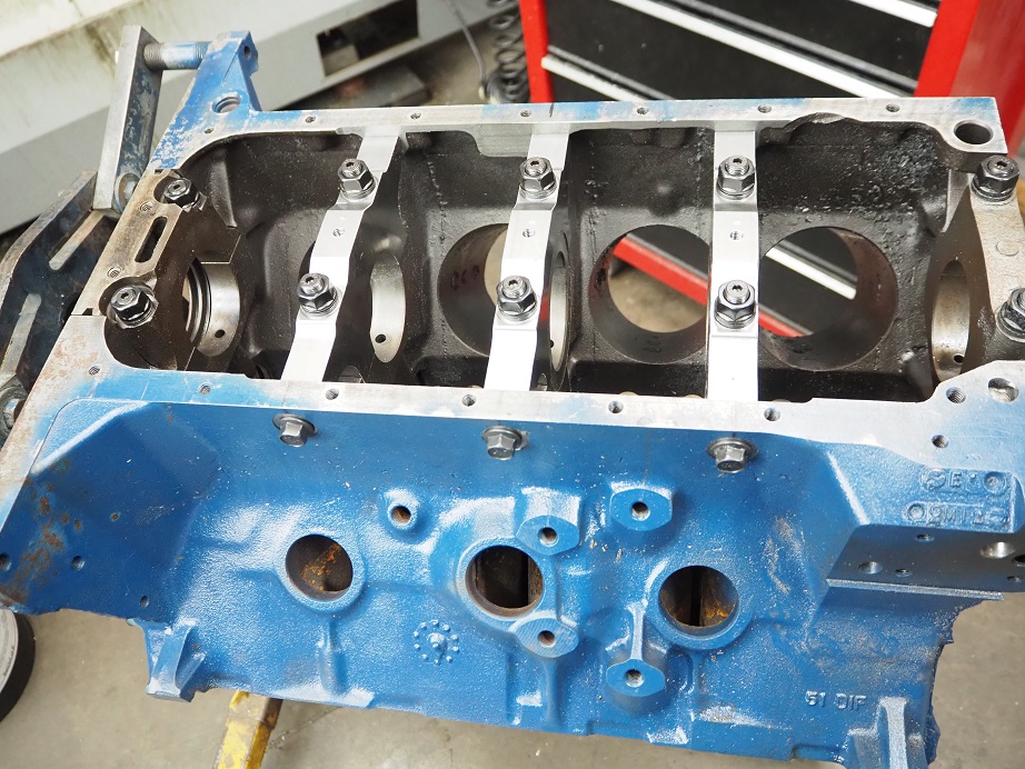
This approach went out the window though, when I went back on ebay and the girdle I was looking at was no longer listed.  However, there was a set of Pro Gram caps listed.  Well, that was going to be a much bigger machining project to make them fit, but I didn't want to wait for the girdle because I have some time now, and won't have it later.  So, I went ahead and bought the set of Pro Gram caps.  I also purchased an ARP main stud kit to use with the caps.  Pictures of the parts are below:


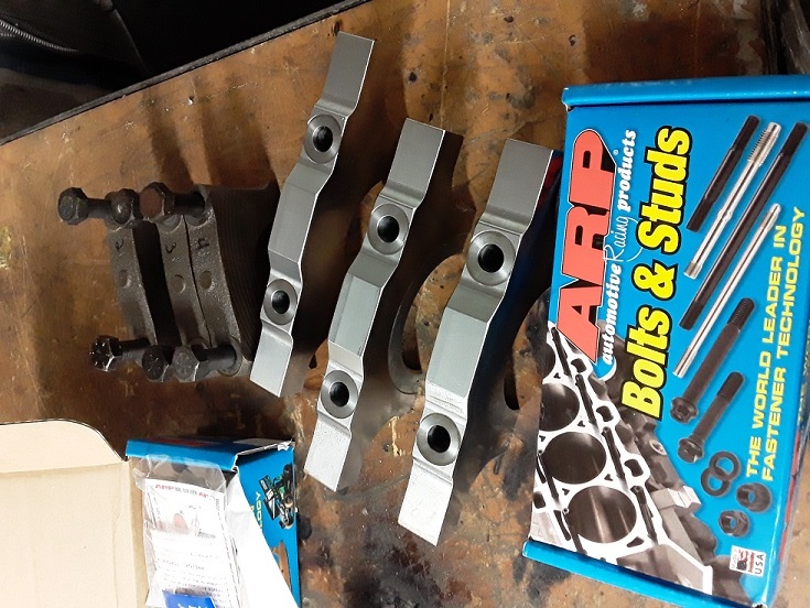
So right off the bat I have more into this project (about $500) than I would have had with the girdle, and I had some serious machine work on the block to do.  When the parts arrived the stud kit looked fine, but unfortunately the cross bolts and washers were not included with the caps, as they should have been.  I contacted the seller and they are supposedly on the way to me now, but to get going on this project I dug up some grade 8 bolts that I could use for the crossbolts.

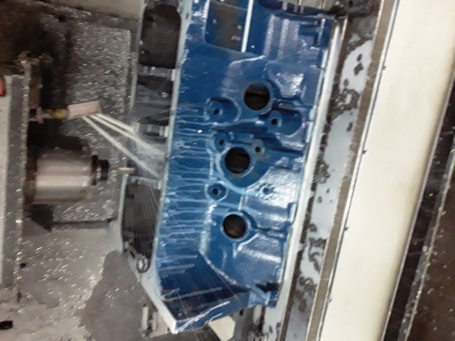
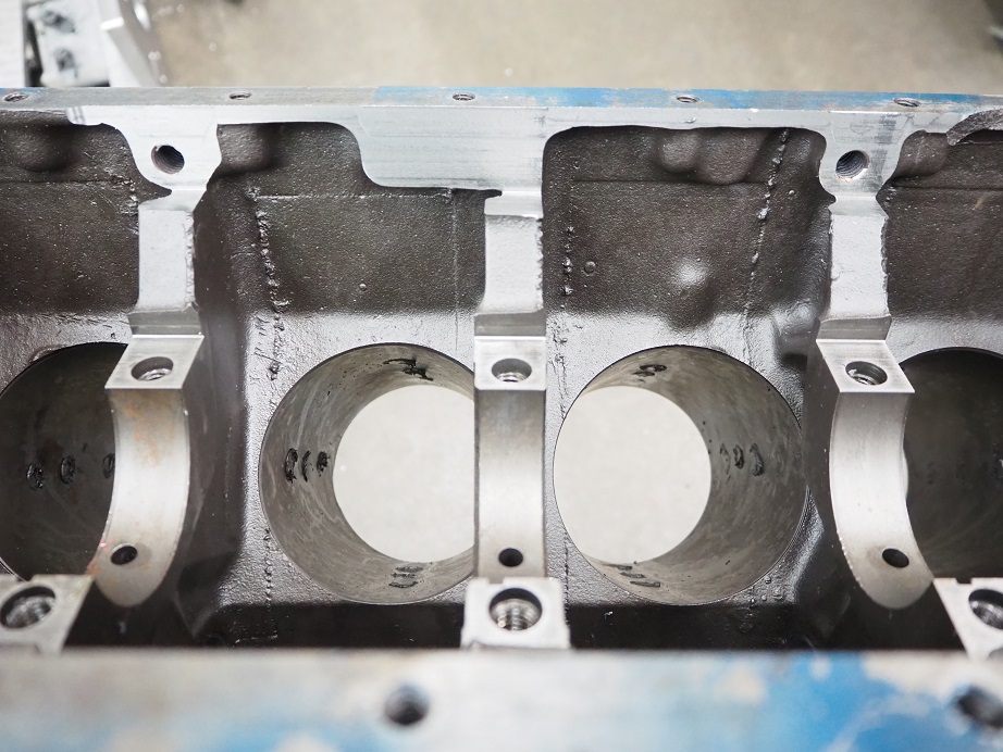
The instructions that came with the caps tell you how to machine the block to make them fit.  One thing I found a little strange was that the instructions were from a company called Billet Speedworks; no mention of Pro Gram Engineering anywhere.  Nevertheless, I hoisted the block up onto my big CNC machine, and cut the sides for clearance to the ears of the caps.  The first picture below shows the block on the machine, and the second picture shows one side of the block after the machining operation is complete:


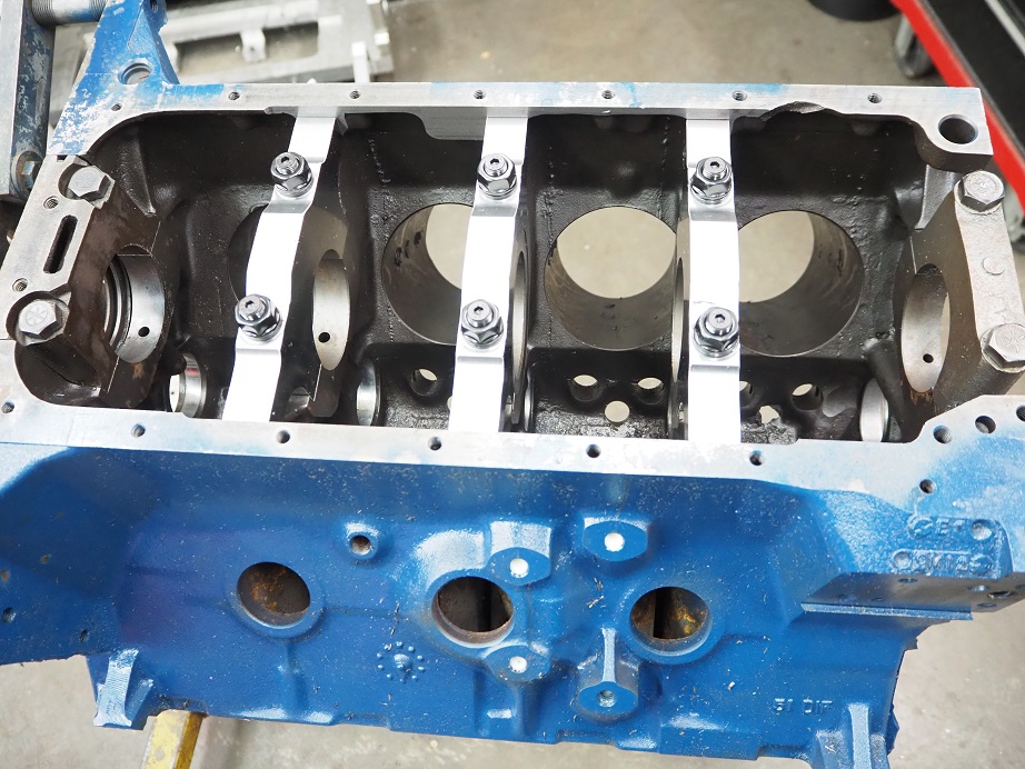
One thing I found helpful is the location of the two holes on the right side of the FE block, as shown in the photo above.  These holes are used to bolt the block to the cradle during Ford's assembly operation and were in the perfect spot to line up with the ears of the caps once they were installed.  I was able to install the caps temporarily at this point (see the picture below), and then use those holes to mark the caps for the crossbolt locations on two of the caps.  This also gave me a reference to the pan rail, so that I could transfer the dimensions to the middle cap, and the left side of the block.


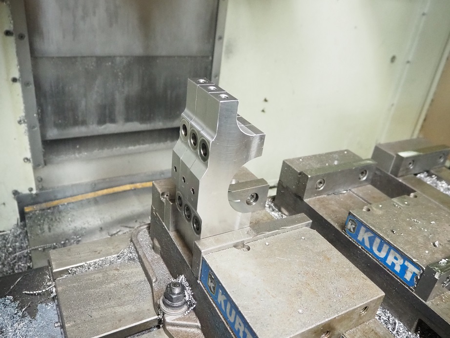
After marking the caps, I transferred them to the smaller CNC machine.  I measured the two marks that I'd made with the caps installed and duplicated those hole positions on all three caps, both ends.  Then I drilled and tapped the ends for 3/8-16 thread.  I also drilled and tapped a 5/16-18 hole in the center of each cap, because I found them difficult to remove from the block after the first test install.  With the tapped hole, a slide hammer can be used to remove them, similar to what is required with some of the aftermarket blocks.  A picture of the caps after the last machining operation is shown below:


While I was at it, I also pulled the stock #5 main cap out and counterbored it 0.275", to allow the nuts for the ARP studs to sit below the pan rail.  I was happy to see that the two studs for the rear cap were shorter, so the studs themselves didn't extend up beyond the pan rail, but left as is the nuts and washers would have.  Counterboring the cap was pretty easy, compared to all the other machining operations I had to do for this project.

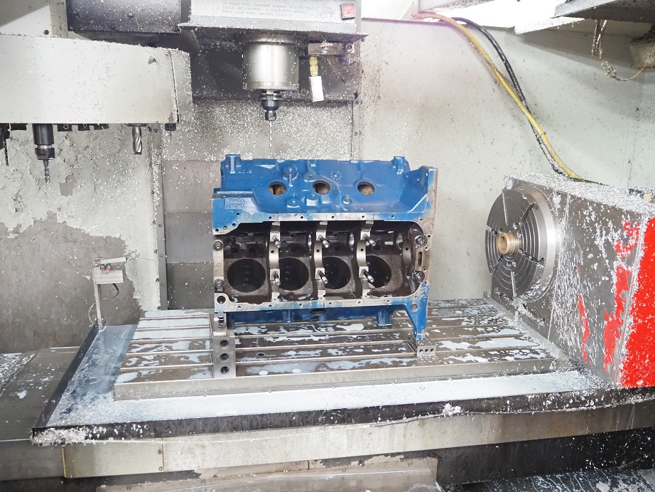
I was hoping that I'd be able to drill the holes in the block for the crossbolts without having to put the block back on the CNC, but that didn't work out.  I tried to do it with my drill press but the travel of the drill press didn't reach all the way down to the block, as it was sitting on the engine stand.  I also tried a hand drill, using a 1-2-3 block as a fixture to ensure that the hole went in square with the side of the block, but I couldn't easily get a clean hole; the drill tended to drift around too much.  So, in the end I gave up and put the block back on the CNC machine to drill and spot face the cross bolt holes, as shown in the photo below:


After flipping the block over to get to the holes on the other side, finally I was able to pull the block off the machine and install the caps and crossbolts:


And of course, I'm not done yet, because the caps are undersized, and so now the block has to be align bored and then align honed in order to get the bearing clearances right.  Depending on how much that costs, I think I'll probably have between $800 and $900 in this project, plus all the machine work I did myself.

Anyone with a Bridgeport or other vertical mill could do what I did to this block, but it is a painstaking operation and takes quite a bit of time; I think I had 8-9 hours in the whole project.  If you have to pay to get the machine work done that I did, seems like you'd be better off just getting an aftermarket 427 block.  I think adding a girdle would be much easier and cheaper, and next time I do something like this that will be my preferred approach.  But for now, I think I've got a block that I'm comfortable with up to the 700 HP level.  I'll add more information to this post as the engine goes together, but it will be a while; pistons are 8-10 weeks out...
« Last Edit: June 24, 2021, 05:08:39 PM by jayb »
Jay Brown
- 1969 Mach 1, Drag Week 2005 Winner NA/BB, 511" FE (10.60s @ 129); Drag Week 2007 Runner-Up PA/BB, 490" Supercharged FE (9.35 @ 151)
- 1964 Ford Galaxie, Drag Week 2009 Winner Modified NA (9.50s @ 143), 585" SOHC
- 1969 Shelby Clone, Drag Week 2015 Winner Modified NA (Average 8.98 @ 149), 585" SOHC


WConley

  • Hero Member
  • *****
  • Posts: 1160
  • No longer walking funny!
    • View Profile
Re: 390 Stroker for FE Power Cylinder Heads
« Reply #1 on: June 24, 2021, 06:33:21 PM »
Geez!  I'm having a bit of size envy. 

Today I was CNC machining some 1 inch pieces of brass and aluminum on the Mini Mill.  I felt pretty good about my day until I logged on here...
A careful study of failure will yield the ingredients for success.

cjshaker

  • Hero Member
  • *****
  • Posts: 4459
    • View Profile
Re: 390 Stroker for FE Power Cylinder Heads
« Reply #2 on: June 24, 2021, 08:45:43 PM »
With all the work and effort you've put into it, and considering its intended purpose, had you considered pinning the caps? I know the crossbolts will help with any cap movement, but pinning adds an extra ounce of prevention. I think the BBM blocks are pinned also. Besides, it's easy to suggest more work when you're not the one doing it..lol
Doug Smith


'69 R-code Mach 1, 427 MR, 2x4, Jerico, 4.30 Locker
'70 F-350 390
'55 Ford Customline 2dr
'37 Ford Coupe

jayb

  • Administrator
  • Hero Member
  • *****
  • Posts: 7405
    • View Profile
    • FE Power
Re: 390 Stroker for FE Power Cylinder Heads
« Reply #3 on: June 24, 2021, 09:32:30 PM »
I hadn't thought about doing that Doug, that would be a nice feature to add to this setup.  But I think it would be difficult to get the pins in the block and the holes in the cap machined so that they lined up perfectly.  These caps are a really tight fit in the block registers, so laterally there would be no room for error in the machining operations.  Getting them in exactly the right spot, both laterally and fore and aft, seems like it would be tough.  I'd be particularly concerned about #3, since the thrust bearing flanges have to line up just right.

I would guess that the aftermarket blocks that use alignment pins probably install the caps in a semi-finished state, then line bore the main saddle and also machine the surfaces for the thrust bearing with the caps assembled and torqued.  That way everything is perfectly lined up.  Adding caps with pins to a block where the main saddle has already been machined is a more difficult problem, I think...
« Last Edit: June 24, 2021, 10:38:48 PM by jayb »
Jay Brown
- 1969 Mach 1, Drag Week 2005 Winner NA/BB, 511" FE (10.60s @ 129); Drag Week 2007 Runner-Up PA/BB, 490" Supercharged FE (9.35 @ 151)
- 1964 Ford Galaxie, Drag Week 2009 Winner Modified NA (9.50s @ 143), 585" SOHC
- 1969 Shelby Clone, Drag Week 2015 Winner Modified NA (Average 8.98 @ 149), 585" SOHC


Stangman

  • Hero Member
  • *****
  • Posts: 1696
    • View Profile
Re: 390 Stroker for FE Power Cylinder Heads
« Reply #4 on: June 24, 2021, 10:21:45 PM »
Nice work Jay are these the things you do when your bored :)

cjshaker

  • Hero Member
  • *****
  • Posts: 4459
    • View Profile
Re: 390 Stroker for FE Power Cylinder Heads
« Reply #5 on: June 25, 2021, 12:43:39 AM »
Adding caps with pins to a block where the main saddle has already been machined is a more difficult problem, I think...

When asking the question, I was picturing how it might be done and was thinking the same as you. But machinists, which I am not, always seem to find innovative and original ideas on how to do things. I actually thought the thrust might be the easiest, since you have two perfectly machined surfaces at right angles to determine measurements from. Regardless, with the studs and crossbolts, it's probably overkill on anything short of a full out build.
Doug Smith


'69 R-code Mach 1, 427 MR, 2x4, Jerico, 4.30 Locker
'70 F-350 390
'55 Ford Customline 2dr
'37 Ford Coupe

blykins

  • Hero Member
  • *****
  • Posts: 4821
    • View Profile
    • Lykins Motorsports
Re: 390 Stroker for FE Power Cylinder Heads
« Reply #6 on: June 25, 2021, 05:54:38 AM »
I'd much rather have the cross bolted caps than a girdle.   A girdle is a machining nightmare.  Pan rails have to be zero'd and surfaced, caps have to be cut down, surfaced, etc.  Unless you build some "preload" into the system, you will still have room for the caps to squirm, even if a very finite amount.

Obviously, on an FE, the pan rail holding the girdle down is an added bonus above a SBF/BBF girdle, but if the caps wanted to move away from the block bad enough, I think they still would.  On SBF's, I've seen the blocks split in half with the girdle just holding the main caps together.

You see aftermarket blocks with cross bolted caps.  You never see aftermarket blocks come with girdles. 

You need to provide this service, Jay.  Not a lot of guys like to do it.  Lots of labor involved.

Brent Lykins
Lykins Motorsports
Custom FE Street, Drag Race, Road Race, and Pulling Truck Engines
Custom Roller & Flat Tappet Camshafts
www.lykinsmotorsports.com
brent@lykinsmotorsports.com
www.customfordcams.com
502-759-1431
Instagram:  brentlykinsmotorsports
YouTube:  Lykins Motorsports

My427stang

  • Hero Member
  • *****
  • Posts: 3929
    • View Profile
Re: 390 Stroker for FE Power Cylinder Heads
« Reply #7 on: June 25, 2021, 06:59:14 AM »
I am no machinist or CnC programmer, but are the main bolts and pan rails consistent enough to make this a automatic CnC operation?
---------------------------------
Ross
Bullock's Power Service, LLC
- 70 Fastback Mustang, 489 cid FE, Victor, SEFI, Erson SFT cam, TKO-600 5 speed, 4.11 9 inch.
- 71 F100 shortbed 4x4, 461 cid FE, headers, Victor Pro-flo EFI, Comp Custom HFT cam, 3.50 9 inch

6667fan

  • Hero Member
  • *****
  • Posts: 719
  • Every Second Counts
    • View Profile
Re: 390 Stroker for FE Power Cylinder Heads
« Reply #8 on: June 25, 2021, 07:34:55 AM »
Jay, I like your sonic read out form. Would a template be available? Proprietary?
It is something I would run copies of for my builder to use.

Do you have a hoist system in that shop or are you humping those FE blocks into the machines yourself?

Thanks for sharing the step by step on that mission.
JB


67 Fairlane 500
482 cid 636/619.
Tunnel Wedge, Survival EMC CNC heads, Lykins Custom Hydraulic Roller, Ram adjustable clutch, Jerico 4-spd, Strange third member with Detroit Locker, 35 spline axles, 4.86
10.68@125.71 1.56 60’

jayb

  • Administrator
  • Hero Member
  • *****
  • Posts: 7405
    • View Profile
    • FE Power
Re: 390 Stroker for FE Power Cylinder Heads
« Reply #9 on: June 25, 2021, 08:44:28 AM »
Having done this once, I do NOT want to do it again.  It isn't like you can just install the block on the CNC and go.  To begin with, you need to indicate on each main cap register to make sure the block is parallel with the X axis of the mill, and then lock the block down so that it doesn't move during the machining operations.  Locking it down is a problem because there really isn't any flat surface that you can rely on to fix the block in the Y axis.  I ended up putting bolts in two of the water pump holes and two of the bellhousing bolt holes, rotating them so that one side of the bolt was vertical, then bolting some blocks to the mill table to contact the vertical surface of the bolts.  Not a real solid arrangement.  Then I had to thread in more bolts to use for holding the block down on the table.  It would be one thing if I could somehow come up with a fixture that every block would sit into and that I could indicate off of, but there's just no way that every block would line up the same way.

I've never done a girdle, but comparatively speaking the machining operations would be simple.  Spot facing the caps is easy.  I don't think that squaring the pan rail is even necessary, provided that you can accurately measure the distance between the girdle and the top of the main caps, but even if you did have to do it, it wouldn't be that hard.  The question mark to me about a girdle is how much additional strength would it offer, but I figure it would have to help a lot.  We're trying to prevent twisting of the #2 and #4 caps, to avoid breaking the block, and the girdle ought to be pretty good for that.  It wouldn't be as good as cross bolting, but for the power levels you're trying to get out of a 390 block, it ought to be plenty adequate. 

Next time I do one of these, assuming the girdles are available, that's the way I'll go...
Jay Brown
- 1969 Mach 1, Drag Week 2005 Winner NA/BB, 511" FE (10.60s @ 129); Drag Week 2007 Runner-Up PA/BB, 490" Supercharged FE (9.35 @ 151)
- 1964 Ford Galaxie, Drag Week 2009 Winner Modified NA (9.50s @ 143), 585" SOHC
- 1969 Shelby Clone, Drag Week 2015 Winner Modified NA (Average 8.98 @ 149), 585" SOHC


jayb

  • Administrator
  • Hero Member
  • *****
  • Posts: 7405
    • View Profile
    • FE Power
Re: 390 Stroker for FE Power Cylinder Heads
« Reply #10 on: June 25, 2021, 08:50:57 AM »
I am no machinist or CnC programmer, but are the main bolts and pan rails consistent enough to make this a automatic CnC operation?

Ross, I don't have any data to support this statement, but I'd bet a lot of money that the blocks are nowhere near consistent enough to fixture the same.  I think it's a good bet that the main cap registers are all going to be parallel and aligned with each other, but relative to an outside surface of the block where it needs to be fixtured?  No way.

Once the block is aligned properly and fixtured so that it won't move, then an automatic CNC operation will work, and in fact I wrote a program to make the cuts.  But getting the block to the point where it can be machined is the challenge...
Jay Brown
- 1969 Mach 1, Drag Week 2005 Winner NA/BB, 511" FE (10.60s @ 129); Drag Week 2007 Runner-Up PA/BB, 490" Supercharged FE (9.35 @ 151)
- 1964 Ford Galaxie, Drag Week 2009 Winner Modified NA (9.50s @ 143), 585" SOHC
- 1969 Shelby Clone, Drag Week 2015 Winner Modified NA (Average 8.98 @ 149), 585" SOHC


jayb

  • Administrator
  • Hero Member
  • *****
  • Posts: 7405
    • View Profile
    • FE Power
Re: 390 Stroker for FE Power Cylinder Heads
« Reply #11 on: June 25, 2021, 08:54:02 AM »
Jay, I like your sonic read out form. Would a template be available? Proprietary?
It is something I would run copies of for my builder to use.

Do you have a hoist system in that shop or are you humping those FE blocks into the machines yourself?

I just use an Excel spreadsheet for the sonic check data, nothing proprietary about it.  PM me with your address and I'll mail you a blank copy.

I do have a hoist to move heavy items onto the mill, the fixture for machining my intake adapters is over 150 pounds, so I use the hoist primarily for taking that on and off the machine.  Worked fine for the block, too...
Jay Brown
- 1969 Mach 1, Drag Week 2005 Winner NA/BB, 511" FE (10.60s @ 129); Drag Week 2007 Runner-Up PA/BB, 490" Supercharged FE (9.35 @ 151)
- 1964 Ford Galaxie, Drag Week 2009 Winner Modified NA (9.50s @ 143), 585" SOHC
- 1969 Shelby Clone, Drag Week 2015 Winner Modified NA (Average 8.98 @ 149), 585" SOHC


blykins

  • Hero Member
  • *****
  • Posts: 4821
    • View Profile
    • Lykins Motorsports
Re: 390 Stroker for FE Power Cylinder Heads
« Reply #12 on: June 25, 2021, 09:09:35 AM »
You'd be surprised on how far the pan rails are out on factory stuff.   We did one block with the girdle and decided to never do one again.  You end up chasing your tail in circles trying to get everything spotted.
Brent Lykins
Lykins Motorsports
Custom FE Street, Drag Race, Road Race, and Pulling Truck Engines
Custom Roller & Flat Tappet Camshafts
www.lykinsmotorsports.com
brent@lykinsmotorsports.com
www.customfordcams.com
502-759-1431
Instagram:  brentlykinsmotorsports
YouTube:  Lykins Motorsports

jayb

  • Administrator
  • Hero Member
  • *****
  • Posts: 7405
    • View Profile
    • FE Power
Re: 390 Stroker for FE Power Cylinder Heads
« Reply #13 on: June 25, 2021, 09:34:41 AM »
You'd be surprised on how far the pan rails are out on factory stuff.   We did one block with the girdle and decided to never do one again.  You end up chasing your tail in circles trying to get everything spotted.

So, what's the issue?  Are they not flat, or are they not parallel to the cap registers, or?
Jay Brown
- 1969 Mach 1, Drag Week 2005 Winner NA/BB, 511" FE (10.60s @ 129); Drag Week 2007 Runner-Up PA/BB, 490" Supercharged FE (9.35 @ 151)
- 1964 Ford Galaxie, Drag Week 2009 Winner Modified NA (9.50s @ 143), 585" SOHC
- 1969 Shelby Clone, Drag Week 2015 Winner Modified NA (Average 8.98 @ 149), 585" SOHC


blykins

  • Hero Member
  • *****
  • Posts: 4821
    • View Profile
    • Lykins Motorsports
Re: 390 Stroker for FE Power Cylinder Heads
« Reply #14 on: June 25, 2021, 09:39:56 AM »
You'd be surprised on how far the pan rails are out on factory stuff.   We did one block with the girdle and decided to never do one again.  You end up chasing your tail in circles trying to get everything spotted.

So, what's the issue?  Are they not flat, or are they not parallel to the cap registers, or?

Yep.
Brent Lykins
Lykins Motorsports
Custom FE Street, Drag Race, Road Race, and Pulling Truck Engines
Custom Roller & Flat Tappet Camshafts
www.lykinsmotorsports.com
brent@lykinsmotorsports.com
www.customfordcams.com
502-759-1431
Instagram:  brentlykinsmotorsports
YouTube:  Lykins Motorsports

jayb

  • Administrator
  • Hero Member
  • *****
  • Posts: 7405
    • View Profile
    • FE Power
Re: 390 Stroker for FE Power Cylinder Heads
« Reply #15 on: June 25, 2021, 10:03:58 AM »
Seems like that wouldn't be that tough to correct.  One big advantage of machining the pan rail is that you can use a big cutter, maybe a 3" diameter facing mill, and it wouldn't matter if the block was perfectly square in X and Y on the machine. That would save a bunch of setup time.  You would set the block on the table, resting on the china walls, and then measure Z dimension at the cap mating surfaces, shim the block to make them the same height in Z, and then take a cut off the pan rail to square it up with the cap mating surfaces. 

Of course I haven't done it, but it seems like this would be much, much easier than what I had to go through to install the crossbolt caps.
Jay Brown
- 1969 Mach 1, Drag Week 2005 Winner NA/BB, 511" FE (10.60s @ 129); Drag Week 2007 Runner-Up PA/BB, 490" Supercharged FE (9.35 @ 151)
- 1964 Ford Galaxie, Drag Week 2009 Winner Modified NA (9.50s @ 143), 585" SOHC
- 1969 Shelby Clone, Drag Week 2015 Winner Modified NA (Average 8.98 @ 149), 585" SOHC


Gaugster

  • Sr. Member
  • ****
  • Posts: 396
    • View Profile
Re: 390 Stroker for FE Power Cylinder Heads
« Reply #16 on: June 25, 2021, 11:24:11 AM »
Thanks for the topic Jay. As I am doing the 390 stroker also this data will be super helpful. I'm leaning towards the girdle as the "Everyman" solution since the crossbolt cost is extensive. I've heard of pinning the caps also and wondered how effective it could be. What crank stroke are you planning? 4.25"? or 4.375"?
« Last Edit: June 25, 2021, 11:31:46 AM by Gaugster »
John - '68 Cougar XR7 390 FE (X-Code) 6R80 AUTO

jayb

  • Administrator
  • Hero Member
  • *****
  • Posts: 7405
    • View Profile
    • FE Power
Re: 390 Stroker for FE Power Cylinder Heads
« Reply #17 on: June 25, 2021, 11:39:54 AM »
I'm going to make the block .020" over, and use the 4.25" crank that I have here, for 442".  Looking at about 10.3:1, with a small cam.  I actually plan to try at least 3 cams.  I'm going to pick some of them myself, and then have Lykins pick at least one for me also.  Probably solid roller, since I'm not a big fan of hydraulics...
Jay Brown
- 1969 Mach 1, Drag Week 2005 Winner NA/BB, 511" FE (10.60s @ 129); Drag Week 2007 Runner-Up PA/BB, 490" Supercharged FE (9.35 @ 151)
- 1964 Ford Galaxie, Drag Week 2009 Winner Modified NA (9.50s @ 143), 585" SOHC
- 1969 Shelby Clone, Drag Week 2015 Winner Modified NA (Average 8.98 @ 149), 585" SOHC


WConley

  • Hero Member
  • *****
  • Posts: 1160
  • No longer walking funny!
    • View Profile
Re: 390 Stroker for FE Power Cylinder Heads
« Reply #18 on: June 25, 2021, 11:41:27 AM »
The rails and cap saddles won't necessarily be parallel, because they are done in different operations on the line.  The saddles are finished with a giant broach that goes through all of them.  Impressive machine!  Generally the block casting will have been "cubed" with earlier big face milling operations. 

You rarely see square deck faces or pan rails on older factory blocks.  The locating features on the machinery were crude, got dirty, and got beaten up / worn.  Newer engines are machined in a much cleaner environment, with nicer equipment.

Jay I hear ya about not wanting to install crossbolt caps for a living!  That is a TON of fussy work.
A careful study of failure will yield the ingredients for success.

cjshaker

  • Hero Member
  • *****
  • Posts: 4459
    • View Profile
Re: 390 Stroker for FE Power Cylinder Heads
« Reply #19 on: June 25, 2021, 11:57:39 AM »
I've heard of pinning the caps also and wondered how effective it could be. What crank stroke are you planning? 4.25"? or 4.375"?

It's very effective at eliminating "fretting", or cap walk under high RPM/stress cycles. The same reason for using dowels for locating rod caps, to eliminate any movement. It's just not really a necessity for the vast majority of builds.
Doug Smith


'69 R-code Mach 1, 427 MR, 2x4, Jerico, 4.30 Locker
'70 F-350 390
'55 Ford Customline 2dr
'37 Ford Coupe

Gaugster

  • Sr. Member
  • ****
  • Posts: 396
    • View Profile
Re: 390 Stroker for FE Power Cylinder Heads
« Reply #20 on: June 25, 2021, 12:19:25 PM »
I've heard of pinning the caps also and wondered how effective it could be. What crank stroke are you planning? 4.25"? or 4.375"?

It's very effective at eliminating "fretting", or cap walk under high RPM/stress cycles. The same reason for using dowels for locating rod caps, to eliminate any movement. It's just not really a necessity for the vast majority of builds.
Okay. What is the exact definition of pinning main caps? I vaguely remember it as basically a dowel/sleeve around the studs. Or are we talking about a separate solid pin?
John - '68 Cougar XR7 390 FE (X-Code) 6R80 AUTO

jayb

  • Administrator
  • Hero Member
  • *****
  • Posts: 7405
    • View Profile
    • FE Power
Re: 390 Stroker for FE Power Cylinder Heads
« Reply #21 on: June 25, 2021, 01:02:04 PM »
Yes, normally there is a pin in the block and a matching hole in the cap.
Jay Brown
- 1969 Mach 1, Drag Week 2005 Winner NA/BB, 511" FE (10.60s @ 129); Drag Week 2007 Runner-Up PA/BB, 490" Supercharged FE (9.35 @ 151)
- 1964 Ford Galaxie, Drag Week 2009 Winner Modified NA (9.50s @ 143), 585" SOHC
- 1969 Shelby Clone, Drag Week 2015 Winner Modified NA (Average 8.98 @ 149), 585" SOHC


frnkeore

  • Hero Member
  • *****
  • Posts: 1135
    • View Profile
Re: 390 Stroker for FE Power Cylinder Heads
« Reply #22 on: June 25, 2021, 02:03:49 PM »
I've done both SBF and FE on my Bridgeport type milling machine, a Lagun, with a 8" riser. You won't have a enough vertical space, for a FE, under the quill (Z axis), to do much, if you don't have at least a 4" riser on a Bridgeport type machine.

Here are some of the things I did to work on the FE.

The hoist is a HF, pickup type mount. I bolted a 3/4 thick steel plate, D&T for the hoist, to my turrets one, lifting eye hole (7/8x9, most BP's are 3/4x10) then, mounted the hoist. I don't plan on lifting more than 300lb, off that bolt and I won't recommend lifting more than 200lb, off a 3/4x10 bolt.

To secure the block, I used a piece of 1" sq alum, in the WP bolts on the front and in the bellhousing bolts, in the rear. I drilled a additional hole, in the front mount, to fit the timing cover holes, when it sets on the pan rails.

The alum mounts, sit a little above the table, so all the pressure is on the block and not part of it on the table.

I'm considering using a girdle on my industrial block, with six, 3/8 dowel pins, into the pan rails and pinning the mains, both to the block and at the top, into the girdle but, that's a ways away.
« Last Edit: June 25, 2021, 02:06:53 PM by frnkeore »
Frank

cjshaker

  • Hero Member
  • *****
  • Posts: 4459
    • View Profile
Re: 390 Stroker for FE Power Cylinder Heads
« Reply #23 on: June 25, 2021, 02:22:25 PM »
Okay. What is the exact definition of pinning main caps? I vaguely remember it as basically a dowel/sleeve around the studs. Or are we talking about a separate solid pin?

Here's a couple links to pictures of the BBM blocks main cap pins. These are very robust.

The block:
https://bearblockmotors.com/wp-content/uploads/2013/10/3-e1402336829139.jpg

The caps:
https://bearblockmotors.com/wp-content/uploads/2013/10/5.jpg
Doug Smith


'69 R-code Mach 1, 427 MR, 2x4, Jerico, 4.30 Locker
'70 F-350 390
'55 Ford Customline 2dr
'37 Ford Coupe

frnkeore

  • Hero Member
  • *****
  • Posts: 1135
    • View Profile
Re: 390 Stroker for FE Power Cylinder Heads
« Reply #24 on: June 25, 2021, 02:35:01 PM »
That's the first I've seen of the BBM blocks and is VERY substantial!

The pinning I have in mind is long, hollow pins, similar to the head bolts but, solid. Thin wall, pressed into the cap, going threw it, into the block and girdle.
Frank

Gaugster

  • Sr. Member
  • ****
  • Posts: 396
    • View Profile
Re: 390 Stroker for FE Power Cylinder Heads
« Reply #25 on: June 25, 2021, 02:51:16 PM »
Thanks for the replies on the pins. I found the article I was referring to. I'm an Electrical Engineer by trade so way out of my wheelhouse and would like to know if something like these dowels have been tried on a regular 2 bolt main?

https://www.dragzine.com/news/building-blocks-getting-the-most-strength-out-of-your-main-caps/

« Last Edit: June 26, 2021, 08:10:18 PM by Gaugster »
John - '68 Cougar XR7 390 FE (X-Code) 6R80 AUTO

Barry_R

  • Hero Member
  • *****
  • Posts: 1915
    • View Profile
    • Survival Motorsports
Re: 390 Stroker for FE Power Cylinder Heads
« Reply #26 on: June 25, 2021, 04:27:07 PM »

So, what's the issue?  Are they not flat, or are they not parallel to the cap registers, or?

All of the above.

Plus the bolt spot faces on the caps are not all at the same height relative to the block surface.

Installing a girdle properly is a PITA

If you wanted to install pins you can put a 1/8 drill hole through both the cap and into the block main face as assembled.  Remove the cap and use that hole to center up for a 1/4 dowel hole - light press sizing in block and a hair larger for a slip fit into the cap.  If it was easy...

Royce

  • Hero Member
  • *****
  • Posts: 777
    • View Profile
Re: 390 Stroker for FE Power Cylinder Heads
« Reply #27 on: June 26, 2021, 11:33:34 AM »
I faced a fretting problem on one of my race Y blocks..  Instead of using spacers between the caps and girdle I had some new caps machined that are flush with the pan rails, then tie it all together with main studs that clamp the girdle to the cap.. Add a couple 3/8 bolts through the girdle asd cap to help prevent caps twisting, or you could pin them and it makes for a very rigid bottom end.. I think I have some pictures . If I can find them I will post
1955 Thunderbird Competition Coupe Altered Chassis "War Bird" 383 Lincoln Y block 520 hp
1955 Thunderbird 292 275 hp Y Block
1956 Ford Victoria 292 Y block

1957 Mercury 2dr Wagon "Battle Wagon" drag car 
1957 Thunderbird Glass body Tube Chassis drag car 333 cu in 500 hp Ford Y block
1961 Starliner 390/375 clone
1965 GT40 tribute w/FE
1966 Falcon Pro Touring project
Kaase Boss 547. 840 HP 698 Torque  pump gas
1992 BMW V-12 5.0
2001 Lincoln 5.4 4 cam.
1968 Cougar XR7

67xr7cat

  • Sr. Member
  • ****
  • Posts: 315
    • View Profile
Re: 390 Stroker for FE Power Cylinder Heads
« Reply #28 on: June 26, 2021, 07:53:31 PM »
Given how tight those caps fit to the block and the cross bolts I don't think is a need for pins.  Considering the main webbing is weak to begin with drilling more holes in it would not help strength.  I remember years ago a discussion on the 400 SBC as to if better to rn a 2 bolt block vs stock 4 bolt because of all the extra holes in the important part  of the webbing. 

jayb

  • Administrator
  • Hero Member
  • *****
  • Posts: 7405
    • View Profile
    • FE Power
Re: 390 Stroker for FE Power Cylinder Heads
« Reply #29 on: July 27, 2021, 03:53:36 PM »
Just a quick update, I got the block back from the machine shop today after align boring and align honing for the new caps.  Cost was $525.  Now waiting for pistons...
Jay Brown
- 1969 Mach 1, Drag Week 2005 Winner NA/BB, 511" FE (10.60s @ 129); Drag Week 2007 Runner-Up PA/BB, 490" Supercharged FE (9.35 @ 151)
- 1964 Ford Galaxie, Drag Week 2009 Winner Modified NA (9.50s @ 143), 585" SOHC
- 1969 Shelby Clone, Drag Week 2015 Winner Modified NA (Average 8.98 @ 149), 585" SOHC


winr1

  • Guest
Re: 390 Stroker for FE Power Cylinder Heads
« Reply #30 on: July 28, 2021, 02:11:40 PM »
Cant wait for results !!

What kind/shape pistons ya order if I may ask ??


Ricky.

jayb

  • Administrator
  • Hero Member
  • *****
  • Posts: 7405
    • View Profile
    • FE Power
Re: 390 Stroker for FE Power Cylinder Heads
« Reply #31 on: July 28, 2021, 04:11:18 PM »
The pistons are CP flat tops to give 10.3:1 compression with my cylinder heads.  Ring package is 0.9mm/0.9mm/3mm, with a standard tension oil ring.
Jay Brown
- 1969 Mach 1, Drag Week 2005 Winner NA/BB, 511" FE (10.60s @ 129); Drag Week 2007 Runner-Up PA/BB, 490" Supercharged FE (9.35 @ 151)
- 1964 Ford Galaxie, Drag Week 2009 Winner Modified NA (9.50s @ 143), 585" SOHC
- 1969 Shelby Clone, Drag Week 2015 Winner Modified NA (Average 8.98 @ 149), 585" SOHC


machoneman

  • Hero Member
  • *****
  • Posts: 3853
    • View Profile
Re: 390 Stroker for FE Power Cylinder Heads
« Reply #32 on: July 30, 2021, 09:24:08 AM »
Geez!  I'm having a bit of size envy. 

Today I was CNC machining some 1 inch pieces of brass and aluminum on the Mini Mill.  I felt pretty good about my day until I logged on here...

Hah! Big mill envy I guess! Now that's funny.......
Bob Maag

Gaugster

  • Sr. Member
  • ****
  • Posts: 396
    • View Profile
Re: 390 Stroker for FE Power Cylinder Heads
« Reply #33 on: August 01, 2021, 05:14:54 PM »
Geez!  I'm having a bit of size envy. 

Today I was CNC machining some 1 inch pieces of brass and aluminum on the Mini Mill.  I felt pretty good about my day until I logged on here...

Hah! Big mill envy I guess! Now that's funny.......
+1

Jay's setup is impressive. For sure it's all about having the right tools for the job. I have a Dremel and that gets me in plenty of trouble. Ha!
John - '68 Cougar XR7 390 FE (X-Code) 6R80 AUTO