Author Topic: Coolest induction system video ever!  (Read 16020 times)

0 Members and 1 Guest are viewing this topic.

turbohunter

  • Hero Member
  • *****
  • Posts: 2509
    • View Profile
Re: Coolest induction system video ever!
« Reply #30 on: January 23, 2016, 11:10:14 AM »
Ok gotcha.
Though I still think the amount of reversion seen in the video is in large part due to the see through material necessary to shape the plenum.
To use your line of thinking, it's a problem but not as big a problem as we see in the vid?
Marc
'61 F100 292Y
'66 Mustang Injected 428
'66 Q code Country Squire wagon


Joe-JDC

  • Hero Member
  • *****
  • Posts: 1502
  • Truth stands on its own merit.
    • View Profile
Re: Coolest induction system video ever!
« Reply #31 on: January 23, 2016, 11:21:16 AM »
A couple of observations from experience.  The wire mesh in the intake gasket is a major airflow hindrance, and the same if used as a screen under the carb spacer.  Darin Morgan is smart, but a couple of his statements are not proven in my experience.  Roughing up a port after it is ported may increase horsepower because it actually removes more material making the port even larger, which always increases horsepower if the port shape is correct.  The same effect would be even more horsepower if he or anyone else were to go back through the roughed-up port with a cartridge roll and smooth out the ports again, increasing the horsepower again.  The net effect is more airflow will increase horsepower up to a point---until velocity is decreased.  And as a final point, the intake valve slams shut every stroke, in effect starting and stopping the air/fuel in the port.  Since there is no piston compressing the air at the carburetor side of the port, the air simply tries to escape/bounce back out the intake to atmosphere.  The same is true in the exhaust, the exhaust is trying to get back towards the exhaust valve because for an instant, there is more atmosphere pressure on the column of exhaust in the system than the there is exhaust coming out of the cylinder.   That is the effect you see on Jon's finger and it gets more severe with increased rpms.  Ideally you want the column/port long enough so that the airflow will be pulsed to ramcharge the air column into the cylinder as quickly as possible the next time the valve opens.  That is where the relationship of the piston/valve/camshaft lobe needs to be optimal for the airflow/cubic inches of the engine.  There is more to be argued, but I will stop.  Joe-JDC
Joe-JDC '70GT-500

machoneman

  • Hero Member
  • *****
  • Posts: 3855
    • View Profile
Re: Coolest induction system video ever!
« Reply #32 on: January 23, 2016, 11:24:42 AM »
Ok gotcha.
Though I still think the amount of reversion seen in the video is in large part due to the see through material necessary to shape the plenum.
To use your line of thinking, it's a problem but not as big a problem as we see in the vid?

Yes, the amount of reversion may or may not be due in part to the odd, box-shaped see-through plenum.  We really don't know though if this is the case.

It would be very interesting to see if a normally shaped plenum cast from some clear material does exhibit a lot less sheeting and droplet formation. Some aftermarket sheet metal tunnel rams do have simple flat, bolt-on plate carb tops. Replacing it with a sheet of Lexan would not be hard and would allow one to peer down at least into a running intake tract and see if things are better. 
Bob Maag

turbohunter

  • Hero Member
  • *****
  • Posts: 2509
    • View Profile
Re: Coolest induction system video ever!
« Reply #33 on: January 23, 2016, 12:34:47 PM »
There is more to be argued, but I will stop.  Joe-JDC
Don't stop on our account Joe.
Personally speaking I will soak up anything anyone with your experience wants to say.
Marc
'61 F100 292Y
'66 Mustang Injected 428
'66 Q code Country Squire wagon


Qikbbstang

  • Hero Member
  • *****
  • Posts: 892
    • View Profile
Re: Coolest induction system video ever!
« Reply #34 on: January 23, 2016, 12:55:14 PM »
Joe-JDC I believe you may have missed what I was aiming at regarding a flat mesh spanning an air-flow path vs an extended surface area mesh spanning the same air flow path . I'm not sure how it applies to a vapor, but in fluids and gasses restriction is considered marginal (the engineers can live with the differential increase) by adding additional surface area via adding pleats or a bowl shape to the mesh.  Pictured you see a flat mesh and an extended surface area mesh cone both with the same cross section size (span of the passage). 
      I can see in an all out race motor anything in the port adds differential pressure/restriction but passing through a mesh could surely vaporize fuel droplets.  Logic says you'd want the mesh obstruction to have as much surface area as possible: For example instead of one 2" dia mesh screen under each barrel of the 4V carb you'd run (8) 2"x1.6" with one in each runner. Then you could mess with angling the screen's to utilize more surface area and/or put bowls into the screens flat surfaces to increase the amount of media - surface area and void space. 
. Re: The wire mesh in the intake gasket is a major airflow hindrance, and the same if used as a screen under the carb spacer. I believe anything you can do to shatter the fuel into mist nearly nixes any probability for the fuel to coalesce back into droplets.  Don't forget modern production fuel injected motors use a wire screen to determine air flow mass for their computers to work with.

http://www.alchemprocess.co.uk/images/filter006.jpg

   I think about actual droplet(s) of fuel having it made it all the way into the combustion chamber. They do not add to the A:F mixture in the chamber (lean) yet they pass out the exhaust as unburned (rich). When you have rivers of fuel like in Jon's video that's a textbook example of how that false rich/lean mess happens.

jayb

  • Administrator
  • Hero Member
  • *****
  • Posts: 7434
    • View Profile
    • FE Power
Re: Coolest induction system video ever!
« Reply #35 on: January 23, 2016, 01:36:04 PM »
Just my opinions here...

I really, really doubt that a properly shaped plenum would show any difference in the amount of fuel puddling on the walls and bottom.  Think about the pulsing seen in the video, and how strong it was.  Combine that with the fog of air/fuel in the intake manifold, and it seems to me that this kind of puddling is inevitable.  People question whether or not there would be a difference between a carb setup and an EFI setup, where the fuel is injected in the runners, and I would say no.  The pulsing is still going to be present, no matter where the fuel is injected above the valve.  I think that maybe with a direct injection setup, the issue would be reduced, but not as long as the fuel is injected upstream of the valve.

Think about the way people tune for proper runner length in a sheet metal intake.  Everyone is trying to tune for the third harmonic.  What this means is having the third pressure wave arrive at the valve in time to aid in filling the cylinder.  So, when the valve slams shut, the column of air/fuel in the runner and port, which was trying to move into the cylinder, has to stop, and the pressure at the back of the valve bounces off the valve and travels back up the runner.  Once it gets to the plenum, it is reflected back down the runner and arrives again at the valve.  That was the first harmonic.  But the valve is still closed, so the process repeats, two more times.  When the pressure wave arrives back at the valve the third time (third harmonic), hopefully the valve is now open and the pressure wave helps fill the cylinder with air/fuel.  Kaase's finger in the video is showing those pressure waves.

Getting back to the original thought, with those pressure waves slamming back and forth along the intake tract, I can't imagine that injecting the fuel in the runner would make much of a difference in how much shows up in the plenum.  Inside the plenum of the sheet metal intake on my SOHC, there are lots of fuel stains.  Pretty sure there's all kinds of fuel running around in there at high engine speeds.  And I don't care what the plenum is shaped like, with air changing direction so rapidly with the pressure waves, the fuel is not going to stay in suspension, and the plenum is going to get wet.

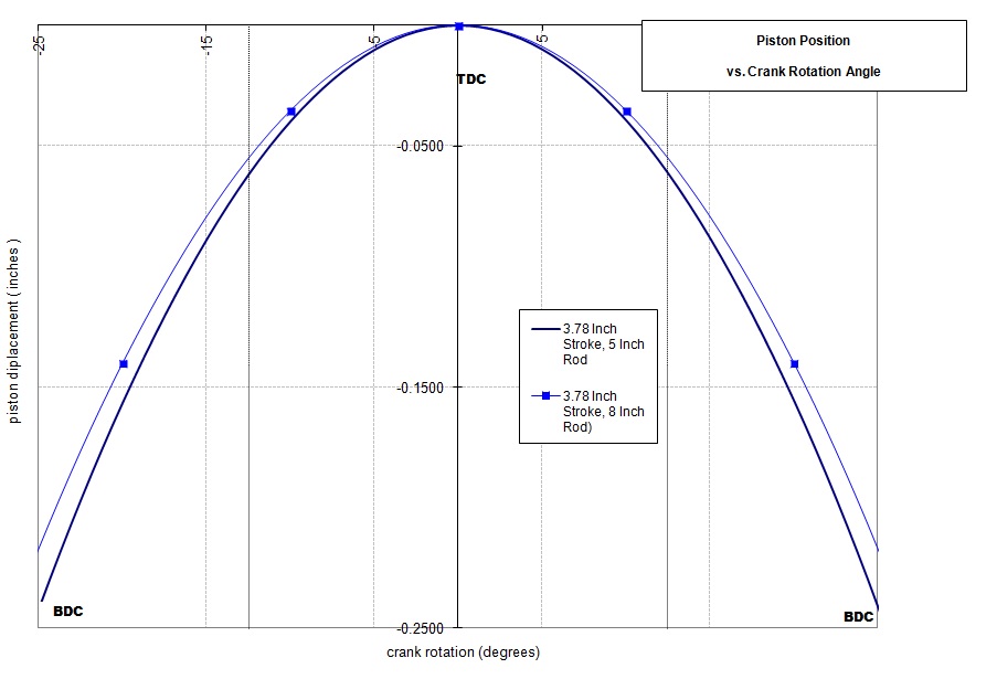
On rod length, I would completely agree with Darin Morgan's assessment; it just doesn't matter that much.  What matters in a racing engine is a tight ring package, so that the piston pin can be as high up on the piston as possible, to reduce the tendency of the piston to rock in the bore.  A lot of people will say that rod length reduces side loading on the piston during the stroke, which is true, but a high pin helps negate that issue from basic leverage.  Also at least a half dozen knowledgeable people have told me that a short rod will pull the piston away from top dead center faster, and get the air/fuel column in the port moving faster as a result.  The graph below, which has exaggerated rod lengths of 5" and 8", shows this idea:


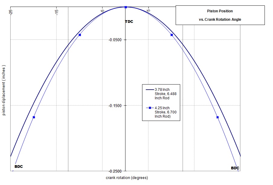
However, putting in some actual numbers like what we normally use as FE guys, it is clear that stroke trumps rod length in this area:


Finally, I have also been told, again by multiple individuals, that big block Chevrolet ports can be larger because those engines have a shorter rod, and they pull harder on the ports as a result.  The math doesn't really bear this out; see the graph below, showing a 427 Chevrolet and a 427 FE Ford:


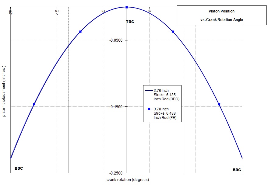
Almost no difference there in piston position versus crank rotation.

Anyway, my advice is to forget rod lengths, and focus on heads, intake manifolds and headers, and cubic inches to make more power - Jay

Jay Brown
- 1969 Mach 1, Drag Week 2005 Winner NA/BB, 511" FE (10.60s @ 129); Drag Week 2007 Runner-Up PA/BB, 490" Supercharged FE (9.35 @ 151)
- 1964 Ford Galaxie, Drag Week 2009 Winner Modified NA (9.50s @ 143), 585" SOHC
- 1969 Shelby Clone, Drag Week 2015 Winner Modified NA (Average 8.98 @ 149), 585" SOHC


turbohunter

  • Hero Member
  • *****
  • Posts: 2509
    • View Profile
Re: Coolest induction system video ever!
« Reply #36 on: January 23, 2016, 02:12:44 PM »
Really enjoy this.
Thanks
Marc
'61 F100 292Y
'66 Mustang Injected 428
'66 Q code Country Squire wagon


Joe-JDC

  • Hero Member
  • *****
  • Posts: 1502
  • Truth stands on its own merit.
    • View Profile
Re: Coolest induction system video ever!
« Reply #37 on: January 23, 2016, 04:47:46 PM »
The mesh/screen wire reduces flow. Period.  When I was working with one of the factory GTP race teams that ported all the heads and intakes for Buick, we tested those screens to see if they would help fuel atomize in the tracts and product more power.  On the flow bench with test equipment to show where the velocity is located in the ports, and measure the speed of the airflow in all areas of the ports, the screens killed/did not help, so they were abandoned.  Removed screens and ran fast again.  There were gaskets available for SBFs with the screens sandwiched in the gasket, and they hurt flow also.  On the rod ratio argument, just putting the ring package as close to the top as possible, and the pin also, automatically increases the rod length to compensate.  Yes, too big a port will respond to a shorter rod that pulls the piston off TDC quicker.  There are crutches for lots of poorly designed parts combinations.  Jon Kaase made that statement a couple of times in his answers.  When I first started cutting 5.0 intake plenums apart for porting, I changed the length of all the runners inside the plenum housing.  The modified plenums were dyno tested and magazine articles were written about the torque and hp increases the changes made.  A short time later the Edelbrock RPM II EFI intake came on the market with very similar changes to their RPM intake.  I believe that a tunnel ram intake should not have the flat under the carbs to create that low pressure area.  That is just my opinion, and until I can weld aluminum well enough to make my own manifold, it will remain untried.  Joe-JDC.
Joe-JDC '70GT-500

machoneman

  • Hero Member
  • *****
  • Posts: 3855
    • View Profile
Re: Coolest induction system video ever!
« Reply #38 on: January 24, 2016, 10:00:00 AM »
Interesting that Jay's custom SOHC tunnel ram has fuel staining where it shouldn't, answering the question that raw fuel is flying around regardless. And yes, between Joe and Jay's answers,
it's apparent that it's the closing of the intake valve that causes the fuel fallout, puddling, etc.

Separating the fuel function from the air function would fix the problem yet direct injection of fuel to the combustion chamber brings up another host of problems, eh?   
Bob Maag

66FAIRLANE

  • Hero Member
  • *****
  • Posts: 565
  • Andy
    • View Profile
Re: Coolest induction system video ever!
« Reply #39 on: January 24, 2016, 07:45:23 PM »
I can't imagine that injecting the fuel in the runner would make much of a difference in how much shows up in the plenum. 

Interesting video and discussion. Just a thought, no experience, not going to war over it.

I would have thought that a multipoint efi set up that that shoots a more precise, already more atomized fuel at the back of the hot inlet valve may show less (maybe not zero) wet fuel in the plenum area. The pulses would be still there but perhaps more vapour than moisture.

But then again maybe it would drop out again once it hit the cold plenum. Heck I don't know!  :-\

TomP

  • Guest
Re: Coolest induction system video ever!
« Reply #40 on: January 24, 2016, 09:33:55 PM »
Joe, what you describe is how I made my FE tunnel ram. As small a plenum possible with no place to puddle. The runners weld together on the bottom and make a sharp V for the plenum floor and the area between the cards is humped floor and sort of hourglass shaped walls.
 That was after consulting and some secret testing with a guy who I think was really onto something.

 He built a sheetmetal intake for a 460, actually a couple, and real sheetmetal... steel! Just for testing and not for a car, if it worked it was going to made from aluminum. In the first intake it was discovered it was soaking wet inside. Then a whole bunch of epoxy was filled in to get rid of the many low pressure areas and no more puddles. That is how I shaped mine.
 Then he wanted to take advantage of that puddling and cut the runners off and built another intake looking like a normal "Pro Stock" style. The floor wasn't flat though it had a V between the runners that collected fuel and a deep well below to store it, From that storage eight small tubes ran to each runner at the lower part. This was going to make legal fuel injection on a car that required a certain carb and was handicapped by a low hoodline. He hoped to prove it on the dyno and then his Superstock car before he was killed in a road crash.

That may or may not have worked but it'd be interesting to have seen the result.

 I wonder if the factories know this already and that is why direct injection is becoming more common?

Joe-JDC

  • Hero Member
  • *****
  • Posts: 1502
  • Truth stands on its own merit.
    • View Profile
Re: Coolest induction system video ever!
« Reply #41 on: January 24, 2016, 11:31:46 PM »
Hood lines dictate runner shapes and designs to a large extent in today's engines, and as such, keeping the fuel out of the various shapes necessary to get the lengths necessary, and volume of air needed for the engine size dictated direct port injection as close to the valve as possible.  Also, keeping the runners dry allow them to be much smoother inside, and easier to mold, made of differing materials that don't have to carry fuel and its inherent fire hazards.  Lots to think about when designing an intake.  Joe-JDC
Joe-JDC '70GT-500

gordonr390

  • Newbie
  • *
  • Posts: 23
    • View Profile
Re: Coolest induction system video ever!
« Reply #42 on: January 25, 2016, 04:44:08 PM »
I had an opportunity to have a conversation with Curtiss Boggs several years ago when I was building my first sheet metal intake for my Bonneville Bike project. He had told me the goal of the plenum was to provide "clean" calm air for the intake runners in a race engine. So for me the first issue I saw in the video was a lack of raised ports coming off the floor of the plenum to help isolate "dirty air" (vortices) and fuel sheeting from influencing the runners. The second was the possibility that the carb set-up is to small causing a highly charged velocity of air fuel entering the plenum washing it out with "dirty air/fuel". As an example the use of enormous Throttle-bodies in efi systems now a days helps in solving the high velocity input issue into an open plenum. Very cool video