Show Posts

This section allows you to view all posts made by this member. Note that you can only see posts made in areas you currently have access to.


Messages - jayb

Pages: 1 ... 480 481 [482] 483 484 ... 494
7216
The ignition control is all run through the eMS-Pro EFI system.  The MSD trigger wheel you see mounted on the front is a relic from my previous crank trigger setup, and is not used anymore.  Behind the harmonic balancer I have installed a Ford 36-1 toothed wheel from a modern Ford engine.  This wheel has 36 teeth, except that one is missing at TDC for #1 to let the computer know when the engine is there.  The sensor just watches the teeth on the Ford wheel, and so it gets a trigger signal every 10 degrees of crank rotation, allowing for very precise ignition control.  You can see this on the RPM output signal from the eMS-Pro; it is very stable right up to peak RPM.  With the distributor, and later the MSD crank trigger, I always had some noise on this signal that ended up showing up in the engine's power output one way or the other.

The eMS-Pro has four trigger outputs for coils that can be configured in a variety of different ways.  I've set mine up to run in "wasted spark" mode.  So, the first trigger output fires the #1 and #6 coils, the second fires the #5 and #3 coils, etc.  When #1 is on the firing stroke and #6 is at overlap, both coils fire, resulting in "wasting" the spark on #6, while #1 gets the spark it needs.  The advantage with the individual coil setup is that there is more time to charge each coil before it fires, since each coil only fires once per engine revolution, rather than four times like a conventional coil triggered by a distributor.  There also is no spark scatter issue or rotor phasing issue with this setup like you would have with a distributor.  When I installed this setup on this engine last summer it picked up 25 HP and smoothed out substantially at the top end; see the graph here:

http://www.fepower.net/dyno_results.html

As a result of this performance I'm really sold on this setup, but it does have a few drawbacks as compared to the FAST setups I've used before.  One is that the injectors can't be set up as full sequential; the options are batch fire or bank fire.  I was worried about this at first when I went to the eMS-Pro, but I shouldn't have been because the engine idled just as nicely in bank fire mode as it ever did in sequential with the FAST setup.  Another issue is that there is not a lot of datalogging power built into the eMS-Pro, so you need to set up some kind of a separate datalogging system to get all the information you need.  Finally, I've had a lot of issues with getting the crank trigger signal to work properly, and even had some issues with that this week.  Tech support for this setup is great though, with Scott Clark (dieselgeek) almost always being available to help with questions and issues.  Overall the eMS-Pro gets a big thumbs up, based on my experiences.

7217
Joel, that would be much appreciated.  I will think on that and get back to you on what would be the right night.  You can come over as long as you drive the '32 Ford...

7218
Non-FE Discussion Forum / Re: Check out my Barn Find '32 Ford!
« on: July 18, 2011, 01:43:08 PM »
You are one LUCKY son of a bitch, Captain Stabbin'!  What a great find!  It needs a big block...

7219
Thanks Ken, but it doesn't really seem like I'm accomplishing all that much.  When the car is running and driving - that's when I'll really get a sense of accomplishment, I think...

7220
I tried to set the plenum volume to the same displacement as the engine, 585 cubic inches.  This is supposed to be an ideal volume for a race application.  The throttle bodies are 4.25" tall in front.  If I had made the plenum the same height all the way back, I would have ended up with around 700 cubic inches of plenum volume.  So, to reduce the plenum volume to the desired amount, I tapered the plenum from front to back.

7221
Today could be subtitled "Equipment Failure Day" because of all the things that went wrong with various pieces of equipment I needed to get the work finished on the engine.  As a result I didn't get as far as I wanted, and have yet to make a full dyno pull on the engine with the new intake.  But I'm getting very close, and I think the bigger question is how badly these further delays will delay the finishing of the car.  I continue to get more and more concerned about making Drag Week, given these repeated delays.  Just have to keep plugging along, I guess...

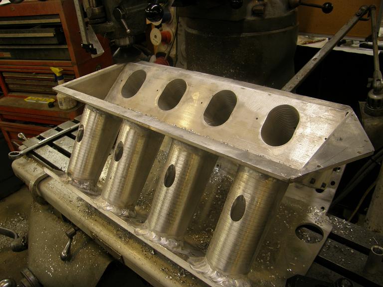
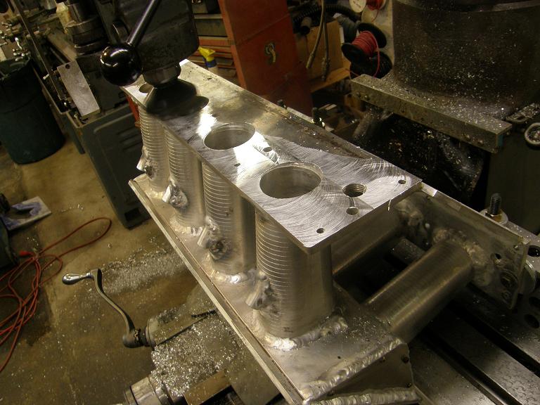
This week I decided to take a couple of days off work to help move this project forward.  I had a bunch of family activities planned for the weekend, so I figured I'd better take a couple of precious vacation days if I was going to get the engine on the dyno this week.  Also, Thursday this week was my son's birthday, and I wanted to spend some time with him on his birthday since my wife was stuck working all day.  I managed to free up about six hours on Thursday to keep working on getting the engine assembled, and once again, despite thinking that I was done with the intake manifold, I still found I had a few more loose ends to tie up with it, including rubbing it down with steel wool to make it look decent, assembling the radius plates into the plenum, drilling and tapping the manifold for a manifold pressure fitting and the air temperature sensor, etc.  Here's a couple of photos from last week's work on the intake, showing the holes bored in the intake for the EFI injector bungs, and also planing the head mating surface of the intake to make it flat.  You can see in the planing photo the shape of the warpage that the manifold showed after the welding; it took about .050" of planing to make that surface flat.


At the end of the night Thursday I still wasn't ready to bolt on the intake, but I wanted to get the engine on the dyno to at least feel like I was making some progress, so I took the engine off the stand, put it on the cart and rolled it into the dyno room.  By 11:00 PM on Thursday night I had it mounted on the dyno, and ready to be hooked up .

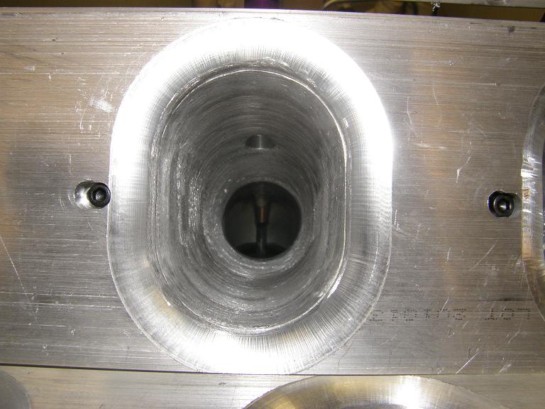
Friday morning I had the whole day up until about 5:00 PM to devote to the engine, and I was up early to get started.  I finished up a couple of minor details on the intake, and then spent most of the morning fitting it to the engine.  This involved some custom gasket trimming and test fitting, to make sure that the ports in the intake lined up with the ports on the heads.  With a custom intake this is always a question mark, and I was prepared to do some last minute machine work if it was required, but everything looked pretty good, so I coated all the sealing surfaces with Motorcraft gray RTV and installed and torqued the intake.  (By the way, the Motorcraft sealer is kind of like Ford's version of The Right Stuff, and it really seems to work well).  Here's a shot looking down one of the intake runners after the intake has been installed.  No restriction here...


After I got the intake installed my friend JC showed up to give me a hand, so between the two of us we got the engine mostly assembled by the time JC had to leave.  Here's a shot of the engine on the dyno stand at this point, with the fuel system plumbing, cooling system plumbing, and belts/pulleys still to be finished up:


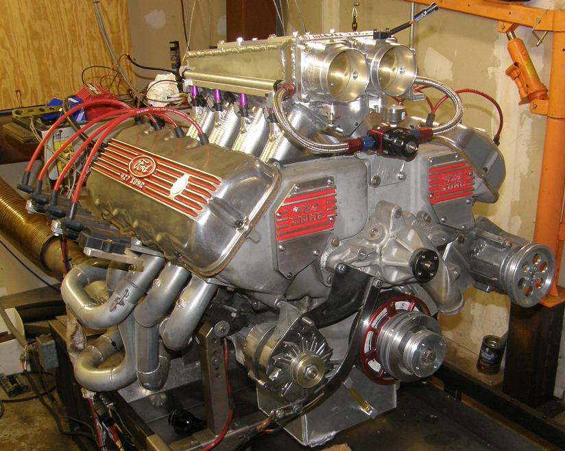
That is a badass looking engine, if I do say so myself ;D  Friday night I had more family plans, and Saturday most of the day was tied up with an activity with my son's Scout troop, plus a neighbor's graduation party, and we also ran out to the local bike store and bought my son a new bike for his birthday.  I did manage to get a couple hours out in the shop on Saturday night, to finish up the plumbing on the engine, and install the EFI box and wiring.

Sunday morning I wanted to get the last hookup details taken care of so that the engine could be fired before 1:00, because after that we had a birthday party arranged for my son which would tie me up for most of the afternoon.  Unfortunately, the day did not go that well, because things started to break.  After getting the fuel system installed on Saturday night I tested it for leaks Sunday morning and found none.  However, when I tried to fill the engine with water I created a flood in the dyno room.  After coming out of the engine, the water for the cooling system empties into an open topped 10 gallon reservoir fitted with a sump pump; when the water in the reservoir reaches a certain level, the sump pump turns on and pumps it back into the cooling water tank.  The flood happened because the sump pump failed, and the cooling system reservoir overflowed when I turned on the pump that pumps the cooling water into the dyno's cooling tower.  This was unexpected, but it had been quite a while, at least six months, since I had used the dyno last, and it seems like every time the dyno sits for an extended period, some little thing goes wrong.  In any case, this wasn't a huge deal, because the sump pump can be purchased at any building supply store, but it would require a trip to the store, taking away time to work on the engine.  I decided to wait on filling the engine, and check the dyno's main water supply system to make sure there was no problem with that as well.  Unfortunately, that check didn't work out very well either, because I nearly created another flood.  There is a valve in the water tank in the dyno stand that is supposed to shut the water going into the tank off when it reaches a certain level, but the water blew by that level and nearly overflowed the stand.  With the engine installed on the stand and all the cover plates in place I couldn't see inside the tank to find the problem; it looked like I was going to have to pull the tank out of the dyno stand, which is not a trivial job.  I left the shop at around noon to go pick up food for the afternoon's birthday party, but on the way back home I stopped at Menards and picked up another sump pump, so at least that problem could be resolved fairly quickly.

By 5:00 on Sunday I was back out in the shop.  Just as a test I turned on the cooling system pump on the dyno to check to sump pump, and sure enough, now it was working again.  I've had them go intermittent in the past, so I'll keep the new pump on hand in case this one goes out again and I need to replace it quickly.  Next I tackled the dyno stand tank, and in about an hour I had it out of the stand and sitting on the floor of the shop; photos below of the tank, and also the back of the dyno with the tank missing:


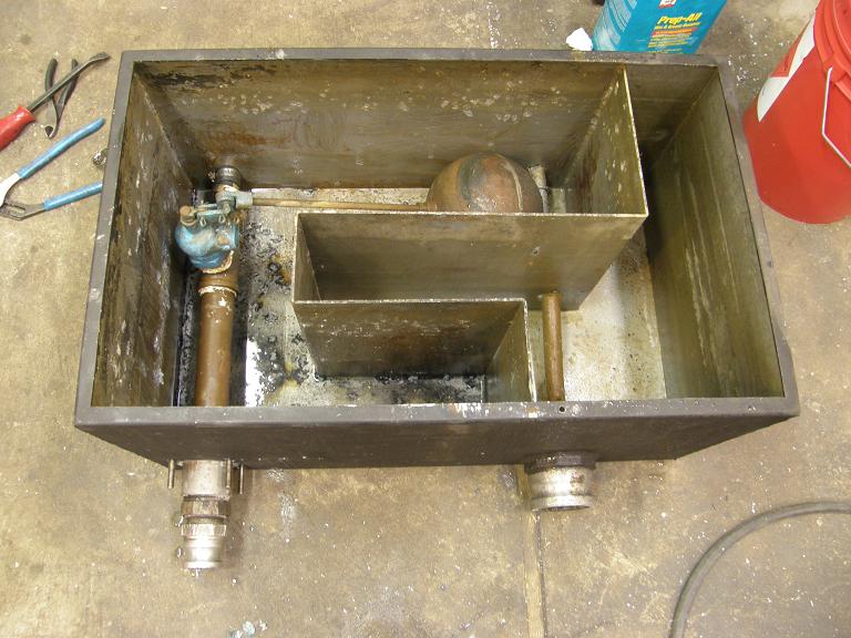
Inspection of the shutoff valve in the tank (which is attached to the big float that kind of looks like a toilet tank float) didn't show any problems, but I was able to locate a fairly major leak in one of the aluminum pipes inside the tank.  Superflow makes the entire tank out of aluminum, including the pipes that run through it.  Seems like a questionable practice to me, given how easily the aluminum could corrode over time.  Superflow gets about $3K for a new tank, and this one is 15 years old.  I've already had to repair it once, because the aluminum pipe that holds the shutoff valve in place corroded through, creating a leak.  I had replaced that with brass pipe when I repaired it before, but there is some aluminum pipe that is welded into the wall of the tank that is not easily replaced.  It was this tubing that had developed a hole, bypassing the shutoff valve and allowing the water to overflow the tank.  I made a temporary repair by sliding a rubber hose over the pipe and clamping it in place over the hole, but I will have to work on a permanent repair for this problem soon.

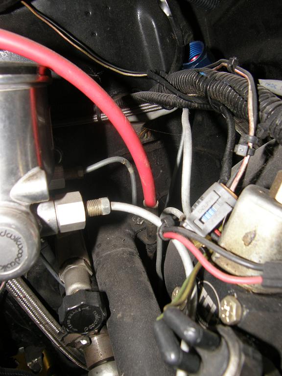
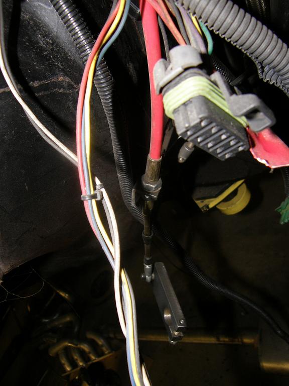
After this repair I reinstalled the tank into the dyno stand, and by 7:00 I was ready to try to start the engine.  However, I found the next equipment failure in this process, my timing light.  The crank sensor used with the eMS-Pro EFI unit is up to the user, and I had two to choose from, a Hamlin 55075 magnetic sensor, and a Ford VR sensor.  The Hamlin sensor is the one I preferred to use, because it has a threaded barrel and I have a CNC'd bracket that I built for it allowing me to slide it along the outside of the crank trigger wheel to easily change the timing.  Unfortunately, no matter what I did, I was unable to get this sensor to work.  It appeared to be working properly when I monitored the signals at the wires, but I got no indication of spark from my timing light.  Finally, not trusting the light, which has given me intermittent problems before, I started checking for spark by pulling a plug wire and putting on an external plug, and watching for the spark.  But still no luck; I would get random, sporadic sparks, and nothing more.  I tried several DIP switch settings on the EFI box to try to  remedy this situation, but nothing seemed to help.  Either the sensor was no good, or the EFI box wasn't processing the sensor signals correctly.  I had spent a lot of time fighting a problem like this with the Hamlin sensor / eMS-Pro combination last summer, and finally gotten it solved, but it seemed at this point that I was back where I started on this.

Finally around 8:00 I swapped out the Hamlin sensor and hung the Ford VR sensor in place.  This time I got good sparking at the plugs, but still no joy from the timing light.  And, unfortunately, I needed the timing light in order to set the initial timing on the engine correctly before it would start.  I tried to do it manually, but the engine would just cough and spit when I tried to start it; seemed like it was retarded.

This week I'll pick up a new timing light, and use the Ford sensor to get the engine tuned on the dyno.  Hopefully this will be done next weekend, and I can work next weekend on getting the fuel system and brake lines installed on the car, and maybe get a start on the wiring.  I need to be making some progress on that stuff soon if I expect to get the car to the track before Drag Week...


7222
But Bob - I drink Killian's and Summit!  I am freshly stocked for the weekend, so I have no beer shortages to deal with  ;D

Seriously, the Minnesota government shutdown here has me concerned about whether I will be able to register the car and get plates for it in the near future.  If those idiots at the capitol don't get their acts together soon, I could be all ready to run and not have plates or tabs for the car.  I can't imagine this shutdown will last another month, but who knows?

7223
I only have a short update this week, because I spent the entire weekend and the free nights I had during the last week working on the sheet metal intake manifold.  Once again I dramatically underestimated the amount of time that was going to be required getting the manifold ready to go.  Tasks I've completed this week include:

- Machining the manifold base for the EFI injector bungs
- Welding the bungs into the intake
- Machining the mounting surfaces of the intake so they are square and flat
- Test fitting the intake
- Enlarging the bolt holes on the intake to make sure the bolts have enough clearance to allow bolting the intake on in the correct position
- Drill and tap the manifold bottom to allow bolting on the radiused runner entry plates
- Port the manifold runner to remove the machining ridges on the inside, and match the top of the runners to the radiused runner entry plates
- Cut the front off the manifold top, weld on the new front that positions the throttle bodies side by side
- Machine the top of the manifold bottom, and the bottom of the manifold top, flat so they will seal
- Machine the top of the manifold top to allow putting the throttle bodies on the top, rather than on the front
- Machine two plates to block the two throttle body openings that are not used
- Tap all the holes around the throttle body openings
- Drill and tap the manifold top and bottom to allow bolting together

All told, between my day off on the 4th and both days this weekend, I counted about 35 hours I've put in on this manifold, and just got it finished up tonight at 10:30.  Part of this was due to a change in plans.  I'm planning on running the throttle bodies on the front of the intake, but I've been told that the manifold will work better if the throttle bodies are  on the top.  This way the air doesn't have to turn 90 degrees when it comes into the intake and goes down the runners; it will have a straight shot down the runners, kind of like a tunnel ram.  I realized this week that it would be fairly easily for me to make a comparison dyno test if I just machined the manifold top to fit the throttle bodies.  This way, I could just move the throttle bodies and change around the throttle linkage to make this test.  I also had to machine up a couple of plates that would cover the two throttle body holes that were not being used, so this took some extra time also.  But I think it will be worth it; I'm looking forward to the comparison test.  If it turns out the throttle bodies on top make a lot more power, I will be stuck with something of an underhood packaging problem, but since I haven't done the hood scoop yet, I could recover from that if necessary.

I was not expecting to still be on the manifold construction this week; I'd been hoping to be off the dyno and on to the next assembly tasks this coming week.  As a result, I'm now getting a little nervous again about making the event.  I still have a LOT of work to do on the car.  I'm crossing my fingers that the dyno work goes smoothly ( you never know), so that by the end of next weekend I can get on with the rest of the work on the car.

I'll try to post some pictures and more details on the engine/dyno next week.

7224
FE Technical Forum / Re: Pond build problems...
« on: July 10, 2011, 10:07:49 AM »
No amount of weeping is normal for an aluminum block engine, Phil.  It sounds like the block is prepared the same as the ones I've had, so I don't think there is any issue there.  I've had similar problems with minor coolant leaks, both with my Pond aluminum block and with a Shelby aluminum block, but this was with Cometic head gaskets, and the Cometics are known for sometimes having this issue.  If you had a head gasket issue that was similar in the past, I'd say that is probaby the same issue.

I've solved the problem in the past with Moroso Ceramic seal.  You put this stuff in the cooling system with water and run it for a few hours, then drain it and add your regular coolant.  I used this stuff on my big SOHC, which leaked a little water out the head gaskets when I first put it on the dyno a couple years ago.  Haven't had any problems since.

http://www.summitracing.com/parts/MOR-35500/

Since you are running your engine out of the car, it would be easy to do this.  The stuff doesn't clog up your cooling system like a normal cooling system sealer might.  I'll bet it would solve your problem.

7225
I'll take those plates, Bill!  I'll send you an email - Jay

7226
Nope, I'm not fully happy with them.  Back in 2005 they were billed as "Pacalloy" springs, and as I understand it Comp was buying the springs from the company that owned that technology.  They used to be dual springs with dampers.  A couple years ago they changed to just dual springs, and took the Pacalloy label off, due to a falling out with the other company I guess.  The quality of the springs has gone down since that time, IMO, the variation in seat pressures that I measured out of the box being a prime example.  But the later versions of the springs were what my SOHC heads were spintron tested with, so they are a known quantity.  As a result I'm sticking with them on this engine.

I'm working on a rocker arm ratio upgrade for the SOHC, and when I get there I will re-evaluate what springs to use.  I'll give some consideration to the Isky springs you mentioned; I've always liked Isky stuff.

7227
Non-FE Discussion Forum / Re: New Member. Go easy on me!!
« on: July 07, 2011, 02:37:29 PM »
Welcome aboard Scott, and glad to have you here.  I'm sure your EFI knowledge will be put to good use...

7228
Did you bother to test the spring pressures of the old valve springs you removed?..... Just interested in knowing if there were any decline and/or any specific springs that lost more pressure that might indicate a location pattern where they were heated more. Sure is scary on new springs to have that percentage variation in the select four springs pressures.  Knowing what I've read on making high dollar spring steel, hardening, shot peening etc it's certainly possible that further variations will contunue to appear with their being run.  The steps going into making valve springs are many and enormously complex.

I tested a few of the old springs, and they were all down about 15-20 pounds on the seat from their original installed values. 

7229
Wow, I had no idea a scoop like that existed!  If I had seen that before I painted the car I think I'd have bought one to see if it might work.  It looks like it would have even worked with the throttle bodies angled out from center.  Thanks for posting that one, Paulie...

7230
FE Technical Forum / Re: How to improve stock auto shifter?
« on: July 04, 2011, 08:00:22 AM »
Here's a couple of pictures of the cable shifter installation on my Galaxie.  The pictures aren't great, but they should give you the basic idea.  The first pictures shows the steering column end; I welded a bracket onto the roll cage tube to bolt the shifter cable onto.  The cable came with a tab on it that allows is to be bolted to the bracket.  You can't see the end of the cable in this photo, but it is simply a threaded steel rod, so I used a spherical rod end that screwed on (it was a 10-32 end I think), and then bolted that onto the tab on the steering column that moves with the shifter.  Not too tough.

The second shot shows the transmission end of the cable.  The cable jacket is threaded on the end, so I built a small bracket that bolts to the floor with a hole in it, that the cable goes through.  The nut on the cable jacket threads onto the threads on the cable jacket to hold the cable firmly in position.  The shift arm shown on the end of the cable is the only difficult part about this installation; its just a piece of steel with a hole drilled in it to fit over the nub of the transmission shift lever.  There is a slot going into the hole in the shift arm, and a bolt to allow tightening of the shift arm onto the transmission shift lever.

Hope this helps - Jay


Pages: 1 ... 480 481 [482] 483 484 ... 494