Show Posts

This section allows you to view all posts made by this member. Note that you can only see posts made in areas you currently have access to.


Messages - jayb

Pages: 1 [2] 3 4 ... 494
16
Non-FE Discussion Forum / Re: Calliope Engine Project
« on: March 14, 2024, 02:43:01 PM »
Kelly, I will be using a 4 axis CNC machine on these heads.  There will be at least two setups required, maybe three depending on the spark plug angle...

Does the 4th come in the form of a rotating pallet? It's probably the least of your machining worries but line boring the throttle shafts (from each end?) may take some reach! I'm sure you've got a plan of attack.

Best,
Kelly

The 4th is actually a trunnion table, with one side bolting to an upright 4th axis and the other side on a pivot.  The CNC machine has 36" from the spindle nose to the table, so with a long drill I can drill at least through two of the throttle bores.  Not sure if I can get three, or all four in one drilling operation, so if I can't, it will be drill two, rotate 180 degrees, and then drill the other two.

17
One other note on this, the forum software is not informing me of new member applications anymore, so I have to go into the admin page and check for them.  A lot of times I don't get to this for several days, so if you have applied for membership and haven't received a response for a few days, please feel free to email me at jayb@fepower.net to let me know.  Thanks!

18
Non-FE Discussion Forum / Re: Calliope Engine Project
« on: March 12, 2024, 04:39:53 PM »
They are 3 valve heads, the spark plug is positioned where the second exhaust valve would be.

19
Non-FE Discussion Forum / Re: Calliope Engine Project
« on: March 12, 2024, 12:49:08 PM »
Kelly, I will be using a 4 axis CNC machine on these heads.  There will be at least two setups required, maybe three depending on the spark plug angle...

20
Non-FE Discussion Forum / Re: Calliope Engine Project
« on: March 11, 2024, 04:36:18 PM »
You're right Doug, a machining error can happen on the first casting.  Happened on my RE and SE heads, happened on my first tunnel port head, and will probably happen on one of these.  Just the cost of getting a good program ironed out.  The good news is that very rarely will you make a paperweight out of one of these things.  Often mistakes can be welded or plugged, and if nothing else the head can be sectioned to make sure that the wall thickness of the ports is where we want it.  On my first tunnel port head I cut one half up in sections to check all those dimensions, then had seats and guides put in on the remaining half so that a valve job and flow testing could be done.  I would envision the same sort of thing with these heads, if there is some error in the machining program that makes them unusable on the engine.  Plus, more of these heads are coming...

The foundry does have some pretty experienced people, and they are all jacked up about this project.  So that is a help.  But the guy who cut the runners, gates, risers, designed the sprue, etc., is probably the guy who deserves the most credit.  There's a lot that goes into that, and his 40+ years of experience designing casting architecture really helps.

21
Non-FE Discussion Forum / Re: Calliope Engine Project
« on: March 11, 2024, 01:32:05 PM »
It's been a pretty exciting few days on this project.  Our first stab at building the mold for the Calliope heads ended when we were not able to make up a good water jacket core from the Ford tooling; we figure that Ford had a machine that blew the sand into these cores, and the foundry we are at didn't have an equivalent machine.  Starting in January Dan and his brother Derek worked to pour some plastic resin into the Ford molds, to make plastic models of the water jacket cores.  These were then glued together into a model of the complete water jacket.  After this model was test fit into one of the drag molds that we made at the foundry, the model was 3D scanned and a file was created electronically.  This electronic model was then provided to the 3D sand printing place, and after a couple weeks Dan had some one piece, 3D printed sand water jacket cores. 

We were able to get into the foundry last Friday.  The water jacket core fit perfectly.  We also had the pattern guy at the foundry, because he was needed to cut the gating and the risers in the correct position so that the head would pour properly.  This was a bit of a shot in the dark, and we figured we had a 50/50 chance to get good castings out of the first pours, but even if the first ones were no good we would be able to modify the gating and riser system to make corrections.

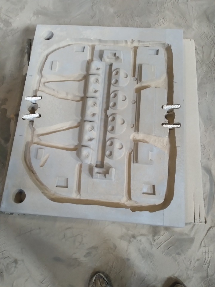
The two pictures below show the drag mold with the gating cut into it, and also with the 3D printed water jacket core installed:


Here's a couple shots of the completed mold before the top was installed:


Starting at the foundry at 5 AM, it took us almost until noon to get the gating cut in the sand, the molds assembled, and two of the heads poured.  It took about 7 ladles of aluminum to fill the mold, which is a lot, but the foundry guys got it done and the pour went smoothly.  We left the foundry on Friday feeling hopeful about the results.

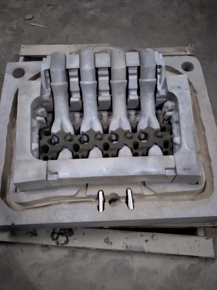
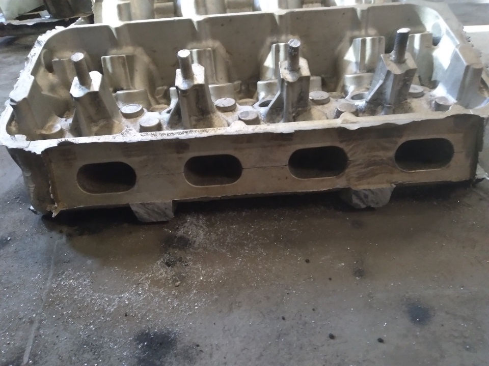
This morning was breakout.  Each mold probably used close to 1000 pounds of sand, and the sand is like a rock, so sledge hammers and impact hammers were needed to clear all the sand away from the castings.  Took probably 30 minutes or more to do the first one, but when we got the sand off initial inspection of the castings looked good!  Pictures of the raw castings are below:


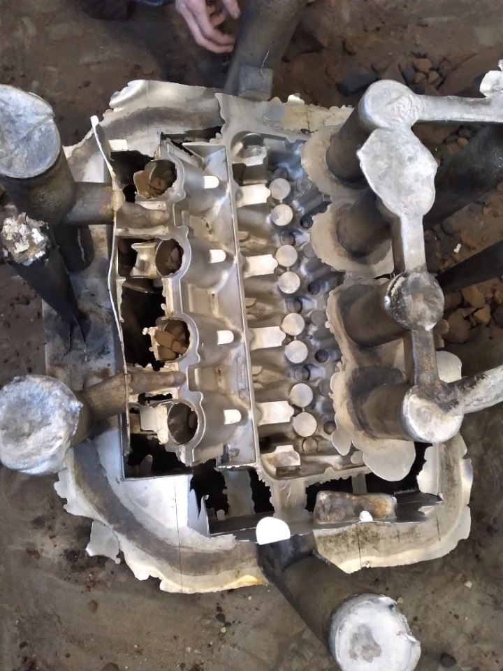
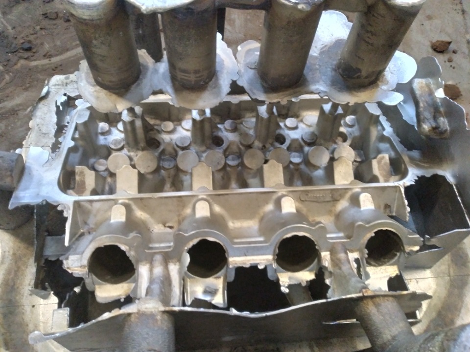
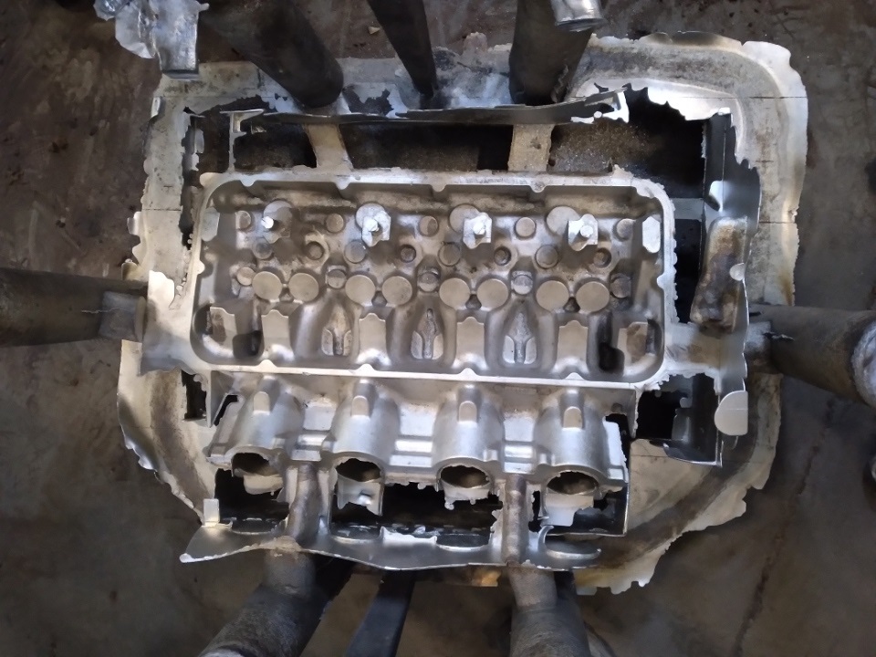
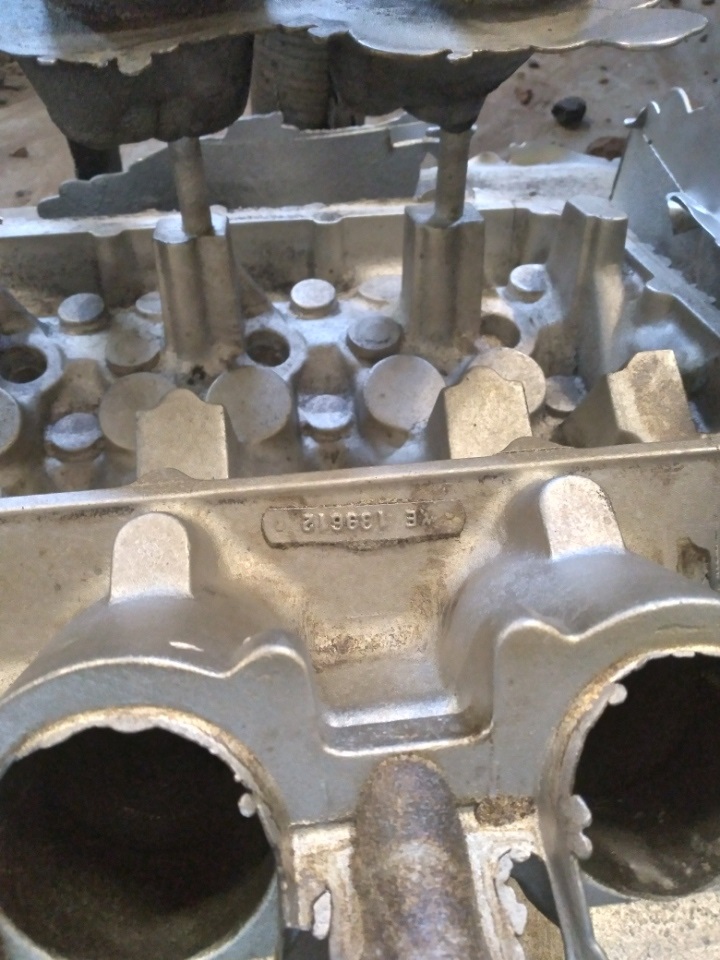
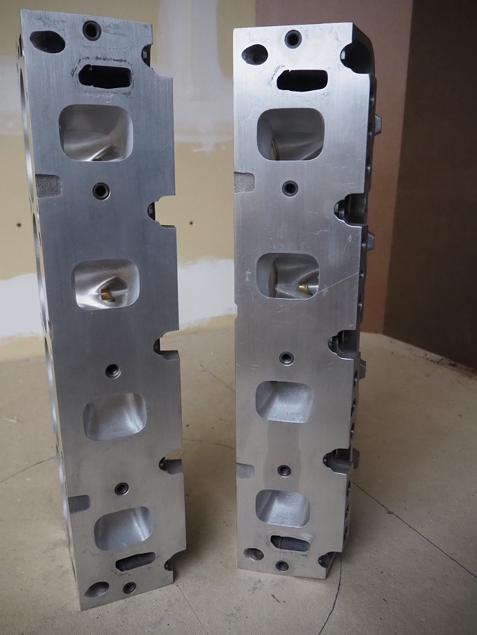
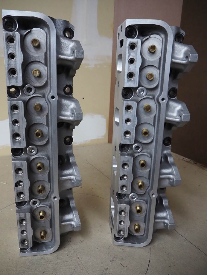
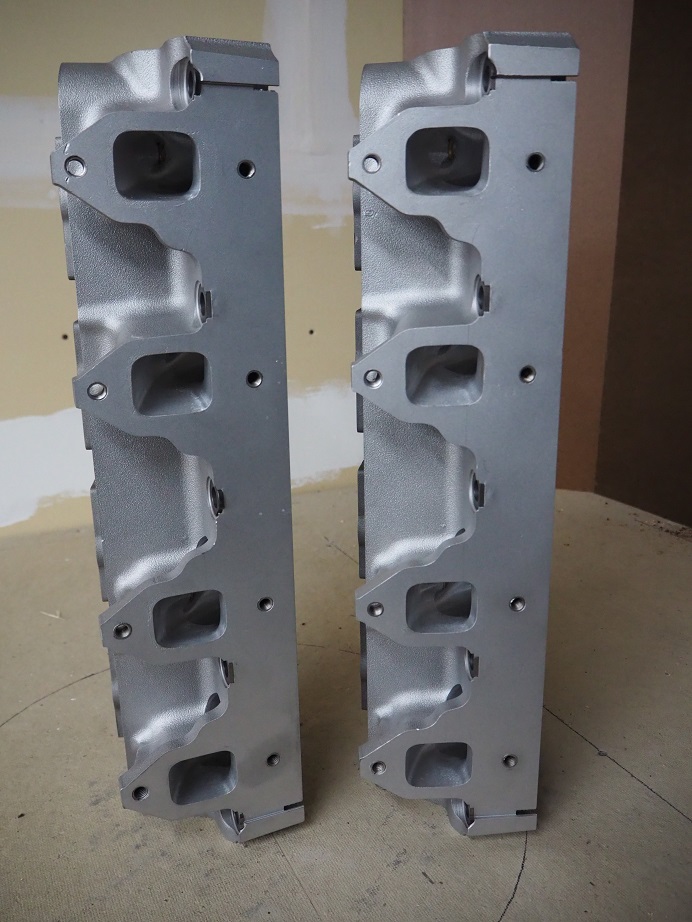
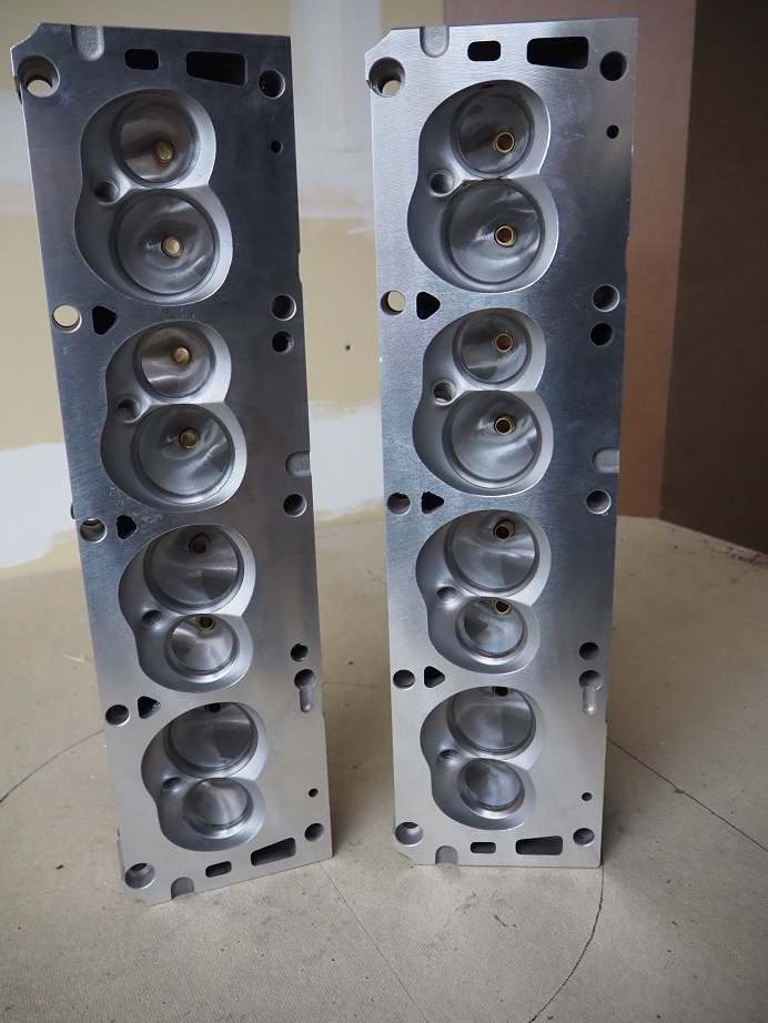
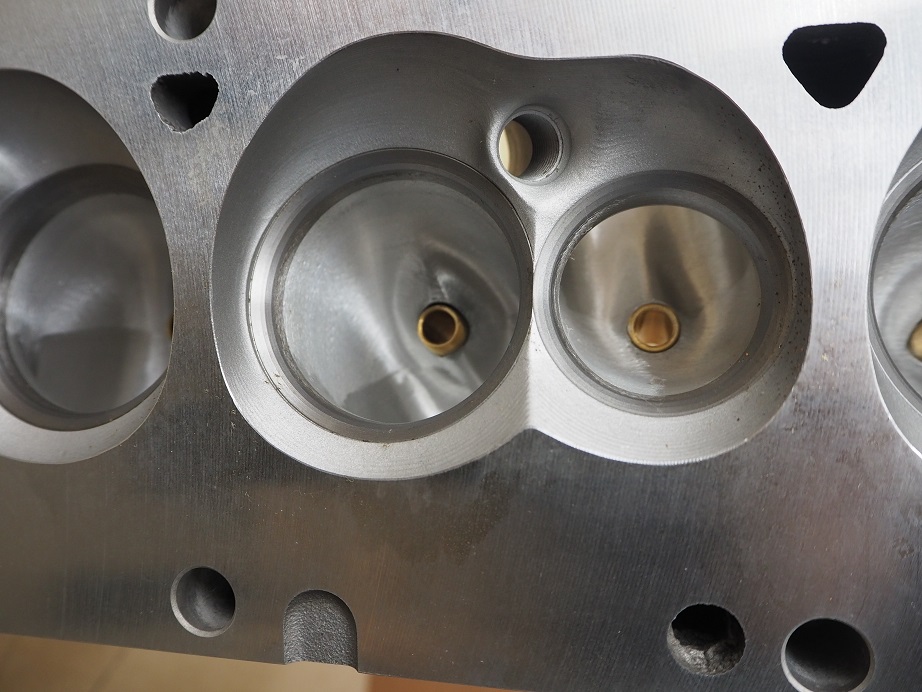
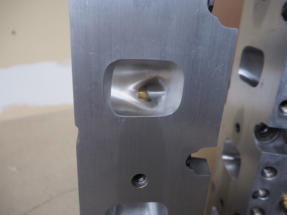
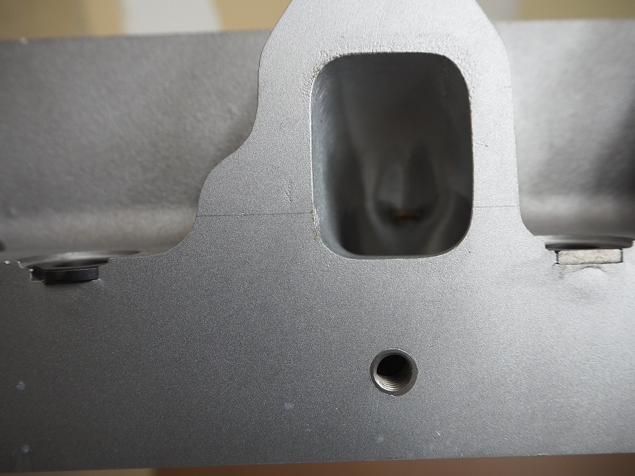
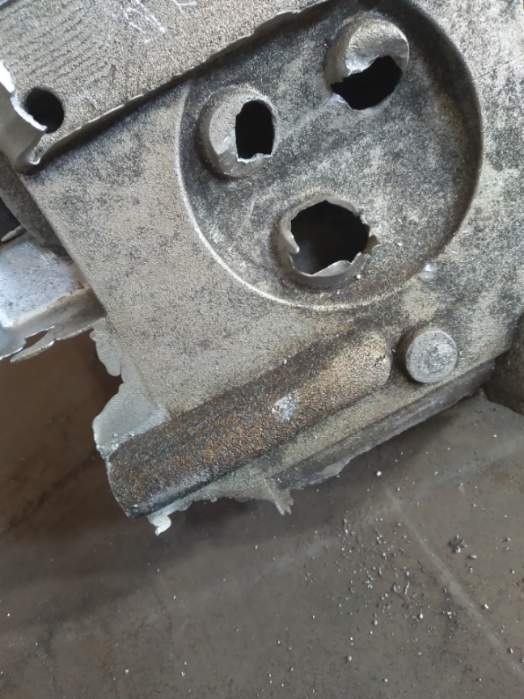
Normally the foundry trims the gating and risers off the raw casting, to leave the "trimmed" casting, but Dan couldn't wait LOL!  He ran off to Menards to get a Sawzall and an electric impact and cut the gating and risers off himself.  This also gave us access to clear all the sand out of the ports and do a detailed inspection of the inside of the ports.  I was worried about this part because the port walls aren't that thick near the water jacket, and if the pour hadn't gone just right, we could see some casting voids in this area.  But to my surprise and relief, both castings looked excellent.  One of the castings had a minor porosity issue in the valve cover area, that can easily be welded; other than that, they are beautiful!  Here are some pictures of one of the trimmed castings:


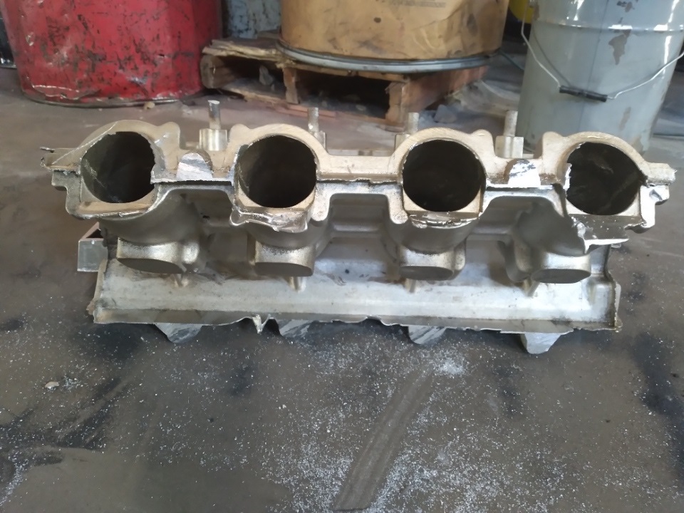
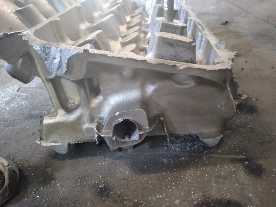
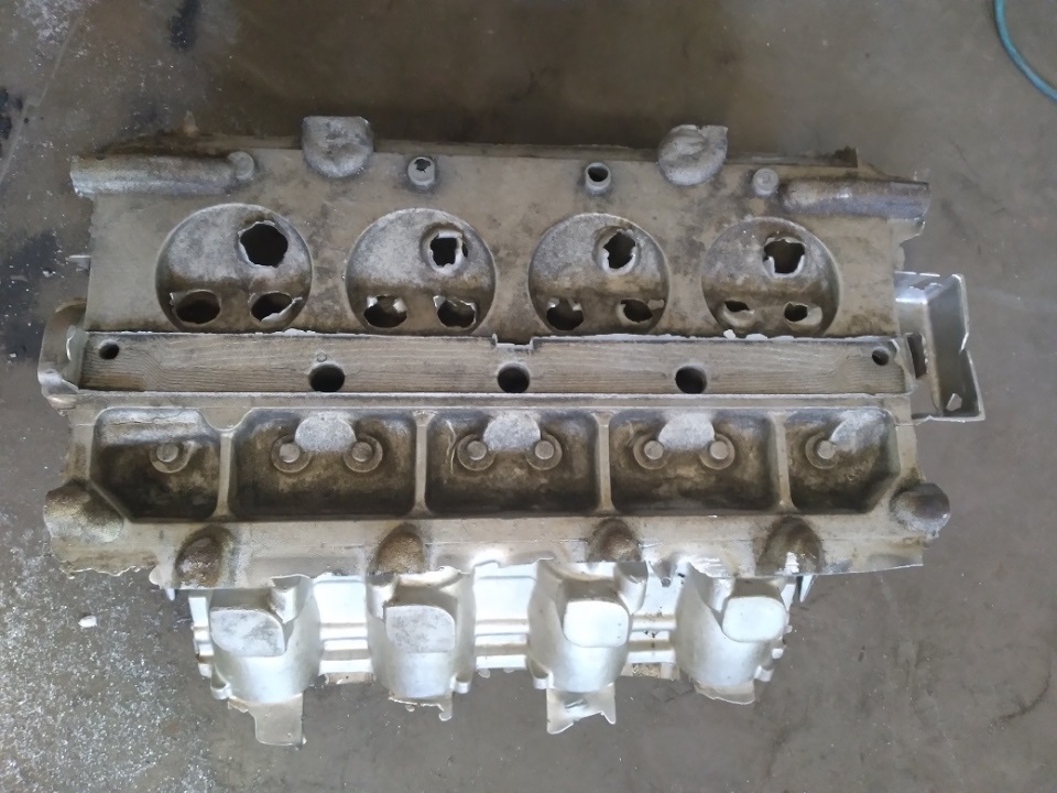
The trimmed castings weigh 67 pounds!  I guess heads get a little heavy when the intake manifold is included in the head.  I think it is just super cool that no one has seen a casting like this since the Ford foundry guys in 1967!

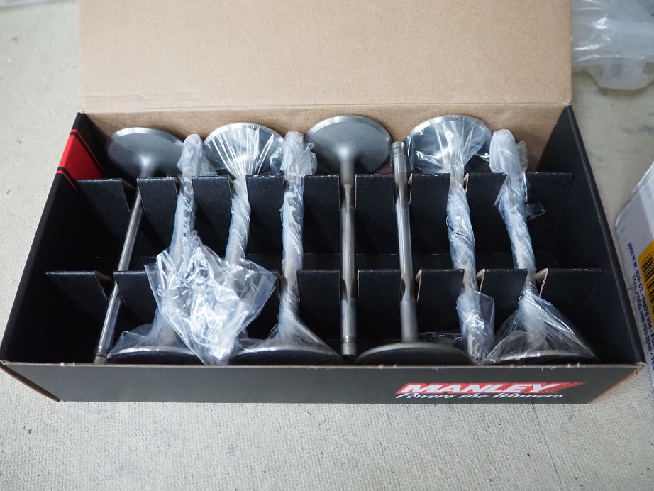
Next steps on these castings are to have the foundry deburr and heat treat them to T6; then it's time for machining them.  It will be a while on this because we will need to design and build fixtures, then write the CNC programs and start the machining operations.  We have a strategy on this already, but still need to settle on valve seats, valve guides, etc.  Dan has found the guy with all the blueprints for this engine and has purchased them, so hopefully soon we will have blueprints to guide our CNC programming.  We are still a long ways away from having a running engine, but with the heads in process we have a pretty good start.  I will update this thread with new information as it becomes available - Jay

22
FE Technical Forum / Re: Who Made this Rod?
« on: March 06, 2024, 09:14:32 PM »
Frank, you should replace those bolts if you use the rods.  Allen head capscrews are known for fracturing at the bottom of the hex; in fact they are illegal via NHRA rules for attaching a transmission bellhousing to an engine.  I doubt that this is ever checked, but the rule is there for a reason...

23
FE Technical Forum / Re: 351C Tunnel Ram ID?
« on: March 01, 2024, 09:34:36 PM »
That's a Weiand 1994 with a single 4 top.  I've never seen one of those tops, I think they only come with the dual four barrel tops now.  Lots of FE guys will use something like that with my FE to 351C intake adapters.

24
FE Technical Forum / Re: CVR water pump question
« on: February 25, 2024, 06:02:42 PM »
Harry, I think they are the same but I'm not 100% sure.  You could buy one and return it if it doesn't fit - Jay

25
Non-FE Discussion Forum / Re: Calliope Engine Project
« on: February 23, 2024, 03:59:41 PM »
Nice article in Hot Rod about the Calliope project.  We are currently waiting for a slot to open up at the foundry so we can cast the heads.  3D printed water jacket cores are done...

https://www.motortrend.com/news/experimental-ford-lemans-v8-calliope-big-block-discovered/

26
Non-FE Discussion Forum / Re: welding helmet mod
« on: February 20, 2024, 10:09:55 PM »
That is a great idea Jim, I need to make myself a setup like that.  In a similar vein, a local friend of mine made a rudimentary air conditioning setup for his 56 Ford using one of those fans, some kind of a small electric water pump, a cooler filled with ice water and a transmission fluid cooler.  He parks the whole contraption on the floor of the passenger seat and swears it cools better than factory AC.

27
Non-FE Discussion Forum / Re: Trannys
« on: February 10, 2024, 11:41:22 PM »
I've had good luck with Performance Automatics C4.  Much less power drag than a C6, and good for at least 750 HP.  There's another outfit call Joel's on Joy in Michigan that is supposed to be even better.  I have one of those C4s to, but don't have a lot of experience with it.  I put at least 20K miles on the PA C4, never a problem in my 511", 706 HP FE.

28
Parts are sold - Jay

29
Doug, the valves are 2.25/1.71.  I don't know the chamber volume, but would guess it would be around 68cc - Jay

30
Starting to sell some of my stash of personal items.  This is a complete cylinder head package for an FE, with the best parts I could buy when I purchased them in 2006.  The heads are the Blue Thunder medium risers, the early ones, not the ones with the huge rectangular ports.  I purchased these CNC ported from Barry R at Survival, and used them on the supercharged engine in my Mach 1 that I ran at Drag Week in 2007.  I don't have flow data on these heads, but when I bought them Barry said they flowed around 360 cfm on the intake, and I have no reason to doubt him. 

Since the engine was supercharged I went with Inconel exhaust valves for durability, and normal stainless steel intakes.  I had the chambers and valves coated at Swain Technologies, and fitted the heads with springs that were much heavier on the intake due to the 17 pounds of boost I was running from the centrifugal supercharger.  The T&D rocker system, which is a dedicated system just for the Blue Thunder heads, uses the standard 1.75:1 ratio, with no extra offset on the rockers.  On the dyno, with an air to water intercooler, the engine made 1030 HP.  In the car, I couldn't get the intercooler to fit where I wanted, so it only made about 900 without it.

After Drag Week I had the heads gone through in preparation for reassembling the engine with them, but got bit by the high riser bug and went that route in the car.  So, these heads have been sitting in plastic since about 2008.  They have a new valve job, new surfacing, and several new valves because some of the old ones showed stem wear.  The ports were also cleaned up in order to remove the CNC tooling marks.  If you look carefully at the pictures you will see that the exhaust side of the heads has also been relieved about 0.100", in order to provide more clearance for the headers (Blue Thunder heads have the exhaust ports raised up just a little, so extra header clearance is good).

The valve springs, retainers, spring seats, and lash caps are included in this package.  The exhaust springs measure about 180 pounds at 2.000", and 520 pounds at 1.300".  The intake springs measure 280 pounds at 2.00", and 640 pounds at 1.300".  This is using my somewhat questionable spring rate checker; wouldn't surprise me if they were off a bit one way or the other.  The retainers are Comp Cams titanium retainers, and the spring seats are Comp steel seats. 

The T&D system requires oiling through the pushrods, so I am also including the pushrods that went in the engine.  Some of the pushrods have some rust spots on them that I've wiped away with WD40 and a Scotchbrite pad.  I would not hesitate to use them again, but you may be fussier than me.  There is one nut missing on the T&D setup; its got to be around here somewhere, but I have not been able to find it yet.  Also, when you purchase the T&D setup they provide washer-like shims that can go under the rocker bar, to adjust rocker geometry; I don't have those either, but they could be easily obtained at McMaster Carr.

This is all really top shelf stuff that I had more than $8K invested in when new.  I want $5500 for the package.  I will not separate it.  Shipping is extra.  I can take a personal check, and also a credit card, but if you use a card I will have to add 3.5% for the credit card fee I get charged.  Pictures are below.  You can message me here, email me at jayb@fepower.net, or call the FE Power number at 952-428-9035.    Pictures are below, and thanks for looking - Jay


Pages: 1 [2] 3 4 ... 494