Show Posts

This section allows you to view all posts made by this member. Note that you can only see posts made in areas you currently have access to.


Topics - jayb

Pages: 1 ... 3 4 [5] 6 7 ... 25
61
FE Technical Forum / Calibrating the Dyno to Ensure Accurate Results
« on: March 26, 2019, 08:24:06 PM »
There's a lot of talk out there about dyno results that are bogus, and I must say I've seen quite a few of them myself.  As an engineer I'm quite concerned with getting accurate and reliable results from my dyno, so today before running Jim's engine I checked the calibration on the torque sensor of the dyno.

This is not a difficult thing to do with Superflow dynos because they provide you with a steel bar, called the calibration bar, that bolts onto the dyno's absorber and activates the torque sensor when weight is applied to the bar.  The decal on the calibration bar is shown in the picture below, and basically gives you a geometric idea of what is going on when you measure the accuracy of the torque sensor:


At the upper left on the decal, the dogbone shaped device is called the torque link, and it is what measures the torque that the engine is producing.  The calibration bar hangs in such a way that it applies torque to the torque link, and weights can be hung on the calibration bar, in the notch shown at the right in the decal.  The notch at the upper left of the calibration bar is the same notch.  This notch positions the weight exactly 3 feet away from the center of rotation of the dyno's absorber, so that if you hang one pound of weight on the bar, you are applying 3 lb-ft of torque to the torque link.  Also, the calibration bar itself has weight, so with only the calibration bar attached, the torque output from the dyno should read 17.5 lb-ft.

On my dyno there are studs coming out of the absorber, which allows you to bolt the bar into place.  See the picture below, with the bar installed:


Once the bar is installed, you can start checking the calibration.  The torque output on the computer screen of the dyno should ready 17.5 lb-ft at this point.  Next, I have a hanger that I built to hang weights on the calibration bar.  Basically what I did was buy a free weight set and hacked it up to make up this hanger, and then used the weights for calibration.  After welding up the hanger, I took it and the weights to the local UPS store and weighed them on their certified scale, to an accuracy of 0.05 pounds. I labeled the hanger and each of the weights with their exact weight, based on the reading from the scale.  The hanger weighs 29.85 pounds, so once it is hanging on the 3 foot long calibration bar, the dyno's torque reading should increase by 3 X 29.85, or 89.55 pounds.  A picture of the hanger is below:


Next, more weights in pairs are hung on the hanger, to increase the torque on the absorber.  Here's the first step, adding two 45 pound weights which together add 270.30 pounds of torque:


Here more weights have been added; see the tag on the 25 pound weight, giving its exact value:


Finally here are all the weights hanging on the bar:


Here are the results from my calibration test today:

Actual Weight          Dyno Reading
     17.50 lb-ft               17.50 lb-ft
     107.05 lb-ft            106.50 lb-ft
     377.35 lb-ft            377.70 lb-ft
     523.30 lb-ft            523.55 lb-ft
     673.15 lb-ft            673.50 lb-ft
     880.75 lb-ft            880.70 lb-ft

As you can see, the torque sensor is extremely accurate.  Any reputable dyno operator ought to have a set of calibration weights, and be able to show his customers exactly how accurate his dyno's torque sensor is.  It is a simple matter to change the dyno's software to increase the torque reading by 5%, 10% or more, and some disreputable dyno operators have certainly done that.  If you go to the dyno and want to be absolutely sure that you are getting accurate numbers, in addition to confirming the weather information you should have the dyno operator calibrate his dyno for you.  It will cost a little extra because you are paying for the dyno operator's time, but you will have peace of mind about the test results.

62
FE Technical Forum / Need a name for the FE Power Cylinder Heads...
« on: March 21, 2019, 07:43:13 PM »
My luck at picking out a catchy name is probably not the greatest, so I'm open to any suggestions (well, almost any suggestions...).  I kind of like the dinosaur parallel, and was thinking of calling them T-Rex heads; I have a great idea for a logo if I go that route, but "T-Rex" seems a little shopworn.  Royce B, our resident MEL and Lincoln Y-block expert, wants me to call them the World Domination heads, but I think the only world they would dominate would be his LOL!  (Sorry Royce, couldn't resist  ;D )  I could probably just be boring and label them with FE Power and a part number, but I was hoping for something more creative.  What say you guys?

63
Private Classifieds / Lots of FE Intakes for sale
« on: March 03, 2019, 12:34:51 AM »
Update:  I've reduced prices on some of these intakes, and can deliver them to the FE Race and Reunion if interested.  The ones no longer available are marked SOLD.  After the FE Reunion they will go on ebay.  Thanks, Jay

I've kept all these intakes around for so many years because A) They make great wall art, and B) If I felt the need to go back and retest anything for my book, they would be available.  But over the years I haven't really needed to do any further testing with these manifolds, and they've just been gathering dust on the wall.  Now that I'm fully committed to my own cylinder head and intake manifold design, I think its time to let some of these go.  Most of them are still hung up on the wall and taking them down to shoot pictures of each one would be very time consuming, and besides, you can see pictures of them in my book  ;D  But if you are interested in one of the intakes and would like some photos before committing to buy, let me know and I'll take the manifold of interest down and get you some pictures, and a detailed description of their condition.

In the pictures of the manifolds on the wall, some of them are blacked out, and these are not for sale.  All the manifolds shown are available for sale:


In the photo above, top row from left to right:

- Offy 360 2X4 intake, Holley carbs will fit, needs spacers to space up the carbs for distributor clearance; $425 $350
- Ford tunnel port 1X4 intake; $850  Sold
- Edelbrock F262 2X4 intake, required Edelbrock-style carbs; $475 $400
- Dove 2X4 Tunnel Wedge style SOHC intake, beat all other SOHC intakes except Hilborn for HP when I tested SOHC intakes; $2250 Sold
- Ford 2X4 low riser intake; $800 Sold
- Dove FE Tunnel Ram, this manifold has a small pinhole between one of the pushrod holes and an intake port.  I sealed it with RTV during testing, but JB Weld or some other epoxy would be a better fix.  It was polished at some point, but could use a shine-up; $1400 Sold
- Munro 2X4 single plane SOHC intake, strongest carb intake between 5500-6500 RPM when I tested the SOHC manifolds, $1950 $1800

Bottom row, left to right:
- Edelbrock Air Gap 2X4 intake, used for dyno testing only $500
- Edelbrock X-F66 Crossram 2X4 intake, $1250
- Blue Thunder Weber intake with 48 IDA carbs.  Carbs have been tuned to work on a 500-600 HP engine.  This combination slaughtered everything else in torque, and in some cases HP, on the 390 stroker and 427 engines during my testing.  $3200 Sold
- Mickey Thompson 2X4 crossram, includes distributor and parts to make the distributor work.  This manifold has a crack in one flange, at the end, but still sealed up well and ran fine on the dyno;  $1050
- High Riser 4V intake; $600 $550
- Ford 3X2 intake with carbs, I've owned this one since the early 1980s.  The carbs were new from Carl's Ford Parts back when I dyno tested the manifolds.  Linkage is repro linkage, also from Carl's if I recall correctly.  The manifold also has a complete hidden nitrous oxide injection system plumbed underneath, but it is the plumbing only; you would need some solenoids, braided line, and a tank to complete.  $1600.


In the photo above, top row from left to right:
- Offy Port-O-Sonics, first and also fourth from left.  One of these has been port matched to medium riser ports, and one is as-cast.  $550 $475 each
- Holley Street Dominator; second from left and also end of the top row.  Again, one has been port matched and one is as-cast.  $500 $450 each
- Offy 360 Dual Port intake, Offy's attempt at an economy intake; $350 $275
- Blue Thunder 4V intake (5th from left), CJ or low riser port size, run on my 69 Mach 1 in 2004-2005; $550 $500
- Edelbrock Victor (6th from left), this manifold was on my 706 HP 511" FE that I ran in my Mach 1 at Drag Week in 2005.  It has been modified to work with a 69-70 Mustang Shaker hood scoop, by milling the carb pad at an angle.  It has also been modified to work with either 4150 or 4500 series Holley carbs; the carb stud holes have been opened up and threaded, and large plugs thread into the holes.  There are smaller, offset holes in the plugs that hold the normal 5/16" carb studs.  By turning the large plugs, you can move the position of the carb stud holes and run either carb type.  The manifold has also been re-machined for a distributor hole, because the original hole was off.  The ports have been matched to the heads which were on the engine, which were larger than stock MR ports.  $750 Sold
- Edelbrock Performer RPM, unported; $375 Sold

Bottom row, from left to right:
- Edelbrock SP2P, what were they thinking LOL!  Probably a pretty good economy manifold, $275 Sold
- Edelbrock F427, also fifth from left, one ported to MR heads, one as-cast, $475 $425each
- Ford 428 PI intake, C7AE-9425-F, $550Sold
- Weiand 7282 intake, probably good for a blower conversion and that's it, $275 $250
- Ford 390 HP intake, $425 Sold
- Offy 360 4V intake, $325  $275


In the picture above, top row, from left to right:
- Edelbrock Streetmaster, as cast, $475 $450
- Edelbrock Victor, Dominator flange pattern, port matched to MR heads, $600
- Edelbrock F380 3X2 intake, $600 $525
- Edelbrock F68 6X2 intake, $1050
- Blue Thunder 4V intake, MR ports, this manifold has been machined for a removable divider, allowing plenum dividers with different amounts of cutout to be tested; $550 Sold
- Blue Thunder 4V intake, MR ports, this manifold has a flat carb pad, supposed to be for a GT-40 application, $550
- Ford Sidewinder intakes, one a little better than the other, lots of helicoils in both, $600 $525 each

Bottom row, left to right:
- C4SE cast iron Ford intake, better intake than the "S" for performance, $75; pick up at my place only, too heavy to ship
- Dove 4V single plane intake for 4150 carb, $700 $625
- Edelbrock Streetmaster intake, this one has been port matched to MR heads and has had the plenum work done, $550 475
- Edelbrock Performer 4V intake (not Performer RPM), as cast; $325
- Edelbrock Victor intake, 4150 carb flange, as-cast; $600 Sold

There are also a few intakes that are not on the wall, so here are those:


- On the left in the photo above is a factory 428CJ intake, date code 8J25, as cast; $400, pick up only since this intake is too heavy to ship.
- On the right in the photo above is a Performer RPM intake, port matched to MR ports; $375 Sold

Also not shown, I have a cast iron "T" intake and a cast iron "S" intake available, $75 for the S and $50 for the T, pickup only.


The two photos above show a hacked up PSE intake adapter and an Edelbrock Torker.  I bought these two together from some guy who was using them as a display.  The water jacket passage had been milled off and was filled, so it was not usable unless you wanted to take the water out of the front of the cylinder heads.  I modified the manifold to accept a pipe fitting and a couple of #10 AN fittings, so it could be used with a remote thermostat housing.  That is how I tested it.  The PSE base has a bunch of epoxy in it, and the 351C ports in the base and the intake manifold have been enlarged to something close to factory Ford 4V port size.  This manifold has also been cut, and if memory serves I had to use two intake gaskets on each side to get it to sit properly on the engine.  Basically, its kind of a mess but it can be made to work; I did the testing with the Torker and a Weiand tunnel ram that is reported in my book with this setup.  $450 for the manifold base and the Torker intake. Sold

All prices quoted here do not include shipping.  Contact me through a PM, or email jayb@fepower.net, if you have any questions.  Also, if you want to buy one of these intakes and take delivery at the FE Reunion to save on shipping costs, I'd be happy to work that out with you.  Thanks for your interest in the manifolds - Jay

64
FE Technical Forum / Another Guess the HP thread - 428 Street Motor
« on: February 25, 2019, 05:16:13 PM »
This engine came to me by way of Tim Meyer, who was going to rebuild it for this customer but lost his engine building guy, so the customer contacted me.  Tim's shop is in Fairmont MN, so on one of my trips his way I picked it up.  The engine had been assembled by the customer but never run, because there had been some issues on assembly.  It was completely torn down when I got it, so I went through it from the ground up.  I found lots of little problems that could have spelled disaster, which I will detail below, but in the end the engine went together and ran fine today on the dyno. 

I will post the dyno results tomorrow night (Tuesday 2/25/19).  In the meantime, feel free to guess the HP and torque, on both 110 octane race fuel and 91 octane pump premium with 10% ethanol; I ran it both ways.  Also, you can try to guess the average vacuum at 850 RPM idle with this setup. 

The engine is a 0.030" over C scratch 428 block with 428 rods, ARP bolts, and Probe forged pistons, with the normal 5/32" moly top ring, cast second, and 3/16" oil ring package.  When I got the engine Tim Meyer told me that there was a question about main and rod bearing clearances being too tight, so I checked them and sure enough, they were WAY too tight, as low as 0.0008" on the rods and just over 0.001" on the mains.  I took the crank in to have it touch-up ground, and then the clearances came in at .0018" to .0025" on the mains and rods.  When assembling the short block I decided that I'd better pull the rings off the pistons (they had already been installed) and check the end gaps.  When I pulled the rings off I found that all the top rings had been installed in the second ring groove, and vice versa!  Could have been a minor issue  ::)  After correcting that the short block went together uneventfully.  However, I also noticed that the frost plugs were the 1-3/4" ones, so I got some 1-49/64" frost plugs and installed those instead.  I had previously opened up the oiling passage from the pump to the oil filter adapter, and tapped all the press-in plugs for screw-in pipe plugs, so I think the short block is pretty solid.

The heads are bone stock Edelbrocks.  I measured the chamber volume at 73cc, and with the 4cc eyebrow in the pistons, static compression ratio calculated out to 10.9:1.  The customer had bought the whole Edelbrock performance package except for the intake, so he had the Performer RPM cam and lifters.  But he wanted to run power brakes, and my own experience with the Performer RPM cam was that it had very limited vacuum, so I suggested a cam change.  We decided on a single pattern hydraulic roller stick, Comp Cams lobe 3613, which has advertised duration of 282, duration at 0.050" of 230, and 0.555" lift.  The lobes are on 110 degree centerlines, and the cam is installed 4 degrees advanced (106 ICL). 

I installed and degreed the cam and the timing set, and then installed the front cover and stock balancer, but discovered a problem with the windage tray.  It looks like it was one of those cheap ebay things, and when it was installed the rod nuts would hit the tray on the way around.  Turned out that the louvers in the windage tray were punched out wrong, and were actually facing in towards the crank, rather than out towards the oil pan.  I would theorize that they put the sheet that makes up the windage tray in the louver press first, then bend it in a different fixture, and whoever did this probably put the sheet into the bending fixture upside down.  Anyway, after some creative work with a ball peen hammer I was able to get the louvers bent down into the correct position, and then the oil pan went on without any drama.  By  the way, this engine uses a high volume oil pump and a stock pump drive, plus a Milodon pan and pickup.  Oil capacity is just about 7 quarts.

In addition to the new cam we also sprung for some Morel hydraulic roller lifters.  Pushrods were 5/16" Smith Brothers, and we replaced the Edelbrock spring package with Comp beehive 26120 springs, in an effort to get this engine to rev a little higher than most hydraulic cam engines.  The rockers were a Harlan Sharp setup, with their end stands and shafts.

For an intake we used an Edelbrock Streetmaster, and I port matched the manifold to the heads, and opened up the plenum per the usual process on these intakes.  The carb is an 800 double pumper rebuilt by Holley, sitting on a 1/2" four hole spacer.  Headers are Hooker Super Comps for a Mustang, with 1-3/4" primaries and 3" collectors.  Ignition is handled by a Mallory Unilite distributor and some kind of a chrome coil, fired through the MSD Digital 6 on my dyno.

So, to recap:

- .030 over 428 block
- 10.9:1 forged pistons, standard ring package
- Stock Edelbrock heads
- Comp hydraulic roller cam, 282/282, 230/230 @ 0.050", 0.555" lift, 110 LSA, 106 ICL
- Port matched Streetmaster intake
- Holley 800 double pumper carb, 1/2" 4 hole spacer
- Hooker Super Comp headers, 1-3/4" primaries, 3" collector

I also experimented with a 1" Super Sucker on the dyno, and will report the results from the best pulls, regardless of the spacer, on pump gas and race gas.  A picture of the engine on the dyno is below.  Any questions on the combination, let me know, and good luck with your guess!


Edit:  Forgot to add, I will be reporting corrected numbers.  It was very cold in Minnesota today, and the barometric pressure is high.  The very unusual result of these weather conditions is that the corrected horsepower and torque is actually LESS than the raw power values.  This is a function of the high pressure and very cool air that the engine is breathing.  Correction factor for most of the pulls was 0.996 or so.

65
Private Classifieds / Headers for SOHC in 64 Galaxie - Sold
« on: February 20, 2019, 03:09:27 PM »
These headers will fit a 64 Galaxie with the stock front suspension, with an SOHC installed on the factory mounts.  I used these headers on my 64 Galaxie in 2007-2008; after that I installed a Morrison front clip in the car and built new headers to match that.  If I recall correctly, a very small part of the inboard side of the driver's side control arm has to be trimmed 1/4" or so to make these fit.  The flanges on these headers are 1/2" thick for a good seal, and will fit either factory or aftermarket SOHC heads.  The primary tubes are 2-1/8" diameter, collectors are 3-1/2" slip-on.  The primaries are close to equal length, but not exact. There are two primary tubes on each side that are slip-fit, for ease of installation.  These headers were ceramic coated when new.  They are solid, no rust holes or anything because the car was never driven in winter (as if LOL!).  They have a bung welded into each collector for an oxygen sensor.  $850 + shipping for the pair.


66
Private Classifieds / 69 CJ Exhaust Manifolds - Sold
« on: February 20, 2019, 02:22:30 PM »
These will be going on ebay in the next week if they don't sell here. 

I'm currently working on making more room in my shop, so I'm liquidating some of my FE parts "collection".  These manifolds were all used for testing in my book, but I don't anticipate the need for further testing with them so I've decided to let them go.  First is a nice set of the long cast iron headers for Galaxies, $1250 $1100 for the pair:  Long cast iron headers are sold!


Next up is a set of Cobra Jet exhaust manifolds, these have a crack near one ear welded but otherwise look good.  $600 $500 for the pair:  Exhaust manifolds are sold!


Finally here is a kind of beat up pair of 390 GT exhaust manifolds.  The ear for the front passenger side is broken off (I don't have the piece) and some of the other ears have been slotted, but they would still work with some creativity.  $100 $80 for the pair: These exhaust manifolds are sold.


If you'd like further details on any of these, please let me know.  Prices do not include shipping to the final destination; pickup available in Rogers, MN.  Payment via Paypal, personal check or money order.  Thanks, Jay

67
Vendor Classifieds / Clear Valve Covers - Limited Availability
« on: February 20, 2019, 12:14:23 PM »
I have about 15 sets of clear valve covers available for sale at this time.  Five of the sets are assembled, and the other 10 will take 1-2 weeks to be finished.  These valve covers consume a lot of CNC time on the billet aluminum rails, and take about 2-1/2 hours per pair to assemble, so I only produce them periodically, on a limited basis.  There are a couple of pictures of the plain valve covers below:


These valve covers are vacuum formed from polycarbonate and are quite strong, and will not yellow with age.  They are in the Cobra Jet style; I have been working on a pentroof version but am not happy with it yet, so all the covers I have are in the CJ style.  They are available plain as shown above, or with an oil cap on one or both covers; this is the same oil cap setup that is available on my cast aluminum valve covers.  The oil caps can also be machined for a screw-in breather, a -12 AN fitting, or a PCV grommet, and the oil cap arrangement has a baffle underneath.  Pricing is $295 per pair for the plain covers, an additional $25 per valve cover for an oil cap, or an additional $35 per valve cover for an oil cap that is machined as described above.  So, if you wanted a pair of valve covers with a machined oil cap on each cover, the price would be $365 for the pair.

I am also now releasing a light kit for these valve covers, with an LED string to light up the valve train.  The light kit is an additional $95.  The light kit can also be added to the clear valve covers I have sold previously, in case you want to light up your covers.  The light kit runs on 12 volts and includes a switch and a fuse, plus the wiring and connectors needed to connect to the valve covers.

Regarding fitment, I can't guarantee that these valve covers will fit all valvetrain setups; in fact I know that the new Comp Cams setup is a problem due to the end stands.  However, a while back I modified the bottom aluminum rail of the covers to make it thicker, so there is room to grind on that if necessary to provide clearance.  I know that the stock rocker assembly will fit, the older Comp Cams and Dove rockers will fit, the Precision Oil Pumps end stands will fit, and I'm pretty sure that the Harlan Sharp setup will fit, although I haven't been able to test fit one directly.  I also believe that the T&D race setup will fit with a little grinding on the bottom valve cover rail, and that the T&D street setup will fit.  I would welcome any information from my customers regarding how these covers fit on the various rocker setups available.

As some of you know I like to test all my products on my own engines and vehicles before offering them for sale.  These valve covers have been on my 68 Mustang for two summers now with no issues, and the light kit was in place all last summer and still works fine, so I am comfortable offering them for sale.  The picture below shows the valve covers on my 68 Mustang; on the passenger side you can see a plain oil cap, and on the driver's side you can see a K&N style breather (from S&B Filters) screwed into the cap. 


Here's the same picture with the lighting kit turned on:


The light kits currently are available in three colors, blue, green, and red.  I like the blue ones, and the green ones match the color of the instrument lights in some of the old cars, so they are kind of cool also.  The red light kits may not be available for long, because my source for them is discontinuing them after their current stock runs out, so if you want the red ones, get them now.

To purchase these valve covers send me an email (jayb@fepower.net), message me on the forum, or call (952-428-9035) with your shipping address.  I will send you an invoice with a total and you can pay from that.  I accept paypal or you can call with a credit card.  Note that after the first five sets of covers are gone, lead time will be 1-2 weeks for the remaining sets.  Any questions please feel free to contact me.  Thanks, Jay


68
FE Technical Forum / FE Power Cylinder Heads
« on: January 28, 2019, 06:46:06 PM »
I thought you guys might enjoy seeing the casting process for my new cylinder heads.  I got finished with the final revision of my cylinder head design a couple months ago.  After designing the heads and intake systems, I ended up designing all the patterns required for pouring the aluminum for these heads, trying to save on the cost of going to a pattern shop.  Along the way I've been fortunate to get acquainted with a guy at a local university who runs their Additive Manufacturing Center, where they do a bunch of 3D printing.  One of the things they 3D print is sand, used for cores in making sand molds for pouring molten metal.  As it happens, this guy also has a 68 Torino and a 428 for it, which I'm currently building for him.  So, I can help him out, and he is certainly helping me out with the casting side of my head project.

I sent the files for the cylinder heads to this guy, and he enlisted the help of one of their students to go over the design.  They ended up changing the whole approach that I had used for pouring the metal; in other words, a new sprue, new gating, and new riser designs.  Then they simulated the design with some casting simulation software, and tweaked the gating and riser design until the simulation said that the finished casting would be solid, with little or no porosity. 

Once that was finished, they 3D printed the sand required for two cylinder head castings, and shipped it over to my foundry.  Today was the big day, where we poured the first head.  The first sand mold used is the bottom, called the drag, and pictured below:


The picture was taken in the foundry, where it is rather dark, and when using the flash a bunch of the details are washed out, so this photo was taken without the flash.  Some of the pictures are kind of blurry because of this, and they all have a sort of green tint to them, but you'll get the idea.  Looking at the drag, you can see the shape of the combustion chambers, and the holes in the middle of the chambers where the core for the ports fit in.  Also in this picture you can see the chill, which is a small block of steel that causes the aluminum to solidify more quickly and helps to eliminate porosity.  The chill was added here because the simulations showed that porosity could be a problem in this area.  Also toward the front of the drag you can see four large holes, where risers are designed in, and also a channel that the aluminum goes into when it is first poured.

This next photo is the core, which basically forms the ports, water jacket, and side surfaces of the cylinder head.  There are two of the cores in this photo.  The picture shows the cores upside down, and you can see the cone shaped areas on the ports that fit into the drag:


The next photo shows the core assembled into the drag.  There's also a close up photo of the top of the core, so that you can see what the top of the port cores look like.  Finally, the third photo below shows this same assembly from a different angle, where you can see the filter that is used to filter the molten aluminum as it is poured into the mold:


The two 1" diameter steel pins in the previous photo are used to help align the drag and core with the cope, which is the top of the mold.  Here's a photo of the top of the cope:


And here is a photo of the entire mold assembled, with the cope positioned on top.  Notice the sleeves in the risers (large holes); these are made of an insulating material and are designed to keep the aluminum hot as long as possible.  As it cools, the aluminum in the head shrinks, and molten aluminum from the risers has to feed back into the rest of the mold to keep the casting from developing porous areas.  Keeping the risers hot as long as possible is one key consideration when making a good casting.


Before the mold is poured, the lead weights shown in the picture below are set on top of the cope.  This is to prevent the cope and the core from floating up on the liquid aluminum as it is poured into the mold.  I think this is because the sand cores are not as dense as the liquid aluminum, and can actually float up on the denser aluminum. 


Now the mold is ready for the pour.  At the foundry I use this is done by hand, using crucibles that hold around 35 pounds of molten aluminum.  Here are two pictures of the pouring process; I was able to get one good one with the flash:


After the mold if filled with aluminum, for several minutes the foundry guys continue to slowly pour liquid aluminum into the risers.  This helps keep the aluminum in the risers hot, so that it can feed into the rest of the casting as it cools.  They call this hot topping:


After waiting 45 minutes or so, the casting has cooled to the point where it can be broken out of the sand.  The 3D printed sand is more difficult to remove than the normal sand used by the foundry, but after some serious beating with hammers and air chisels most of the sand came off.  The sand in the water jacket of the cylinder head was difficult to remove, and I can see that this is going to be something I will have to focus on with these heads.  But after a while we got it all out, as far as we can tell.  I will be running some rods through the water jacket openings in the casting I took home today to try to make sure that no sand remains.  Here are some pictures of the casting as it was broken out of the mold:


After another couple hours the casting was cooled enough to handle, and was trimmed with a saw to remove all the gating and risers.  Here are some pictures of the finished head casting that I took home today:


Of course, as it stands this is just the beginning for this casting.  It needs to be solution heat treated to a T-6 condition, then I need to machine it here on my CNC machine.  It will need seats and guides installed and a good valve job done, then I can flow test it and also pressure check it.  I'm going to try to get this done ASAP, but heat treating will take a couple weeks, and I will also need to machine a fixture for holding the heads on my CNC machine, and then develop all the machining programs to get this done.  I have a second head being cast tomorrow so assuming everything is good with these two heads, I should be able to run them on an engine this spring.  If I find that things aren't quite right as I go forward with this process, I will have to revamp the design and cast more of these heads.  To be honest, I fully expect at least one or two iterations will be required before they are ready for sale.  But getting the first head cast is a big step, and I'm happy with the results so far.  I will post more info in this thread as the project progresses - Jay

69
FE Technical Forum / MOVED: NEW ALUMINUM HIGH RISER HEADS AND INTAKE!!!!
« on: January 12, 2019, 10:36:59 PM »
This topic has been moved to the Vendor Classifieds Board.

http://fepower.net/simplemachinesforum/index.php?topic=6924.0

70
I just wanted to thank everyone for their participation in the forum, and wish you all the best for the holidays.  This forum has been a great way to meet new FE folks, and I've especially enjoyed  meeting some of you in person after getting to know you on the forum.  I'm looking forward to more of that in the coming year, and expect to continue to put out more new high performance FE parts for us all to enjoy in 2019.  Good luck on all your FE projects!

71
FE Technical Forum / FE Power at the 2018 PRI Show
« on: December 05, 2018, 11:18:15 PM »
Once again this year FE Power is exhibiting its products at the Performance Racing Industry show.  Prior to this year's show Barry R and I talked about getting our two booths set up next to each to provide a sort of hub for the FE faithful.  We worked with the PRI folks and were able to make this happen.  This year we made it into the main convention hall; my booth is #4355, and Survival Motorsports is right next door.  Should be lots of fun hanging out with Barry and Marc during the show:


I've been spending most of my time over the last few months working on my cylinder head project.  Because of the substantial changes I've made to the basic head design, its not just a head project; it involves the intake adapter, three different intake manifolds, and a whole new rocker arm system.  I'm please to report that the head design is basically finished, after some significant modifications from the previous iteration.  The water jacket design was an extremely challenging part of this work, and took me 3-4 weeks all by itself.  Also, in addition to the basic head design, I have designed the sand cores required to get the heads cast, and I expect to have the first two prototype castings at the end of January (In fact it should be sooner, but with the holiday shutdowns at the foundries and core shops I'm hedging my bets on the date).

I fully expect the first prototype heads to have some unanticipated problems, but having the first couple of prototypes will allow me to get the machining programs dialed in, even if there are problems.  And any required design revisions go a lot faster than a ground up design, plus the foundry I'm working with on these heads has been pretty quick on the turnaround, so I'm hopeful that I can have some heads to run on an engine by this spring.

Of course in addition to the heads, I'm been working on intakes.  The intake adapter has already been designed and manufactured; it uses my basic high riser and tunnel port casting, but has a different port configuration that either of those.  It also has a valve cover rail that matches the heads, and is actually higher than a high riser valve cover rail, but uses the same valve cover rail angle as a medium riser.  For manifold tops I've designed a billet 2X4 intake, a single 4 Dominator flange intake, and the new design shown in 3D printed form in the photo below, an individual runner crossram style intake.  This intake is designed for street applications, and is EFI only.  One of the design constraints was to keep it under the hood of a 67-70 Mustang (because I want to put this setup on MY car ;-)).  Right now a stock distributor won't fit, but I'm considering machining a special distributor just for this setup.  Otherwise, individual coil packs can be used.  In any case this will have to be a crank trigger setup, because any new distributor will have to be low enough to clear the runners and this will make it difficult to fit a triggering or advance mechanism into the distributor.  As shown, the intake will not allow the hood to shut on my 68 Mustang; the front four ram tube bells hit one of the supports in the hood.  However, a smaller bell on the ram tube will solve this problem.  I also have to move the injector mounts down a little, so that the fuel rails will clear the hood at the front.  But other than that, this intake system will fit.  Imagine popping the hood on your car to see something like this:


Also towards the back of the photo above you can see part of the 3D printed single 4 manifold that will also work with the intake adapter and these heads.

Lastly, I have the rocker arm system finalized and the machined prototypes can be seen at the bottom of the photo above, bolted onto the 3D printed cylinder head.  The rocker system uses a very sturdy steel bar, that bolts into the cylinder head itself, and also  bolts into some special nuts that are used on the head studs.  Stock ARP FE head studs are used.  Bolting the bar into both the flat part of the head and into the head stud locations provides two different angles of attachment, which I think will be very strong and secure. 

The rockers are in pairs, and on four individual rocker shafts.  The shafts are pinned to the heads, and steel caps bolt over the shafts to hold them securely in position.  Oiling is through the pushrods.  The intake ports on the heads are straight in like a tunnel port head, rather than hooking in like a normal FE wedge head, so the intake rocker has a very large offset in order for the pushrod to clear the intake port without having to go through the port like a tunnel port pushrod does.  Valves are very long, over 6", and use a 5/16" stem.  The rockers themselves have needle bearing fulcrums and are machined of hardened 7075 aluminum for strength and longevity.

The cylinder head design has changed somewhat over the last few months, mostly to accommodate the requirements of the water jacket constraints, but also to improve the chamber.  The primary difference is the spark plug location; my original design placed the plug close to the stock FE location, but to get the chamber the way I wanted it I had to move the plug so that it was more underneath the port.  This gives the plug a more central location in the chamber and gets the electrode in a better position.  The picture below shows the exhaust side of the head and the plug location:


The next photo shows the intake side of the head.  The ports are just slightly larger than a stock medium riser port in this 3D printed head, but I plan to do two port versions, one with a smaller port that can be run as-is or ported by someone else, and one with full CNC machining done on the ports, like the 3D printed version.  I've tried to leave enough aluminum around the port so that they could be opened up even more if necessary, but the CNC ported version should be good for 850+ HP right off the shelf, so for most folks that should be plenty big.  As mentioned previously, initial tests on the 3D printed head showed an intake flow of 405 cfm at 0.700" lift.  This flow comes from the fact that the ports are raised a full 1.5" over a stock medium riser port location, and they are also straightened out rather than hooking in towards the cylinder wall.  In addition, the valves on the heads have been moved to a better location for flow.


Next are a few photos of the rest of the display, for those who can't attend the show.  Since my valve covers finally became available I've been able to produce quite a few different varieties, as shown in the photo below.  Also, my tests over the summer of the baffle system on my clear valve covers have proven relatively successful, so I will be making those available soon.  Also note the one picture below with two valve covers; on the CJ style valve cover at the bottom, you can see the spot for the screw-in cap, and the aluminum underneath that forms the baffle.  The top valve cover is not easy to see, but it is my first pentroof style clear valve cover.  I just got the first one successfully vacuum formed this past Sunday, after at least 15 tries.  But I think I have the secret now, and if I am able to get the pentroof style clear valve covers vacuum formed reliably, I will make those available soon as well.


If you happen to be planning a trip to PRI, please stop by the booth and say hi.  It's always great to put a face with the forum logins on this site, and of course PRI is a great place to talk about existing and new projects. 

73
Non-FE Discussion Forum / MOVED: SCJ PARTS VALUE
« on: September 18, 2018, 12:32:23 PM »
This topic has been moved to the Classifieds.

http://fepower.net/simplemachinesforum/index.php?topic=6476.0

74
FE Engine Dyno Results / 482" Street SOHC Specifications
« on: August 20, 2018, 10:28:40 AM »
More information on this build can be found at the following link:

http://fepower.net/simplemachinesforum/index.php?topic=6368.0

Performance Summary:
      Cubic Inches:    482           Dyno brand:  Superflow 901
      Power Adder:    None           Where dynoed:  FE Power
      Peak Horsepower:  715
      Peak Torque:   587

Horsepower and Torque Curves:


Engine Specifications:
   Block brand, material, finished bore size, other notes:  BBM cast iron block, 4.25" bore, block not drilled for oil drainbacks for the SOHC, external drainbacks used
     
   Crankshaft brand, cast or forged, stroke, journal size:  Scat forged 4.25" stroke, BBC rod journals
     
   Connecting Rods brand, material, center to center distance, end sizes, bolts:  Scat H-Beam BBC rods, 6.700" center to center

   Piston brand, material (caster, hypereutectic or forged), dish/dome volume, static CR:  Diamond forged pistons, 35.5cc dome, zero deck, 11.5:1 static compression ratio

   Main Bearings, Rod Bearings, Cam Bearings brand and size:  Federal Mogul 125M 3/4  groove main bearings, Clevite CB-743HNK coated rod bearings, Durabond sideoiler cam bearings, standard SOHC cam bearings for the heads

   Piston rings brand, size, other notes:  Hastings ring package 09024250, 1/16 - 1/16 - 3/16 rings, Moly top ring, cast second, chrome oil rings.  Support rail for oil rings required.

   Oil Pump, pickup, and drive:  Precision Oil Pumps high volume oil pump with 5/16" hex, standard spring, heavy duty pump drive, Canton pickup for cast aluminum Cobra oil pan

   Oil pan, windage tray, oil filter adapter:  Cast aluminum Cobra oil pan, Moroso louvered windage tray, Precision Oil Pumps oil filter adapter with two pipe thread outlets, one used for feeding oil externally to the cylinder heads, the other for the oil pressure gauge

   Camshaft brand, type (hyd/solid, flat tappet or roller), lift and duration (adv and @.050")  Comp 8594 lobes on both intake and exhaust, 300 adv duration, 277
@0.050" lobe lift, 0.723" gross valve lift, 112 LSA, right cam degreed at 107, left cam degreed at 109

   Lifters brand, type:  Who needs lifters??

   Timing chain and timing cover:  Complete Robert Pond Motorsports timing set with the pre-stressed secondary chain and 0.250" roller pins.  Comp Cams stub cam.  Robert Pond Motorsports timing cover.

   Cylinder heads brand, material, port and chamber information:  Robert Pond Motorsports aluminum heads, 120cc combustion chamber

   Cylinder head flow in cfm at inches of lift (28" H2O pressure drop):
      Intake               Exhaust
      .100       71        .100     56
      .200      158       .200   128
      .300      239       .300   195
      .400      304       .400   243
      .500      353       .500   262
      .600      375       .600   268
      .700      375       .700   271
      .800               .800

   Flow bench used, location:  Superflow 600 Bench at R&R Performance

   Intake valve brand, head size, stem size:  Ferrea 2.300", 11/32 hollow stem

   Exhaust valve brand, head size, stem size:  Ferrea 1.900", 11/32 hollow stem
   
   Valve springs brand, part number, specs:   Comp 943 springs, 220 pounds on the seat, 585 at .700" lift

   Retainers and locks brand, part number, specs:  Comp tool steel retainers, Manley machined steel locks

   Rocker arm brand, type (adjustable or non-adj), material, ratio:  FE Power non-adjustable SOHC rockers, roller tip, 4130 steel, 1.3:1 ratio

   Rocker shafts and stands, brand, material:  Rocker shafts from T&D Machine, spring clips from T&D Machine

   Pushrods brand, type, length:  Just say no to pushrods!

   Valve covers, brand, type:  Unknown brand, acquired from customer, powder coated

   Distributor brand, advance curve information:  No distributor, stock distributor modified for oil pump drive only, Crane steel distributor gear

   Harmonic balancer brand:  Romac fully degreed balancer

   Water pump brand, type (mechanical or electric):  CVR Pro-Flow extreme electric water pump with FE Power water pump adapters

   Intake manifold brand, material, porting information:  Hilborn mechanical FI manifold, modified for electronic fuel injection

   Carburetor(s) brand, type:  NA

   Exhaust manifolds or headers brand, type:  Custom SOHC dyno headers

75
Member Projects / 482" Street SOHC
« on: August 20, 2018, 12:01:54 AM »
Just over a year ago I was contacted by a local guy who wanted to build an SOHC engine and put it in a 64 Galaxie.  A man after my own heart  ;D ;D  I usually don't build engines for other people, but in this case, since it was an SOHC and the guy was local, I decided to take on the project.  I hate the idea of someone spending a bunch of money on one of these engines and then getting tripped up by something like what happened to Jason, where the machine shop the installed the cam bearings in his block incorrectly. 

For most of the last year my friend has been collecting parts for this build, including a BBM cast iron block, a 4.25" stroker kit from Barry R with the forged Scat crank and H-beam rods, and the whole SOHC setup from Robert Pond, including heads, front cover, and timing chain setup.  So this was not a rebuild of an existing engine, it was one put together with new parts from scratch.  I figured there would be some massaging of some of the parts required to make everything fit properly, but I was surprised at how easily this one went together.

After the machine work was done, at the beginning of June he brought all the parts over to my place so that I could get started.  And, naturally, we ran into the first delay.  Inexplicably, after prepping the block and installing the crank, I went to start putting the pistons and rods together and there were no spiro-locks included with the pistons.  So, the pistons had come from Diamond, to Barry R, to my friend, then to R&R Performance, then back to my friend, and finally to me.  They either got misplaced or lost somewhere along the way, or they were never included from the manufacturer.  Everything else was there, just no spiro-locks.  I called Barry up and he contacted Diamond to get a replacement set.  And then we waited.  And waited.  It took almost four weeks to get a single set of spiro-locks.  At the end of all this I was emailing Diamond, Barry was emailing them and copying me on the emails, and Diamond just didn't seem to be in any hurry to respond.  No idea why, since I've had good luck with them in the past.  By the way, I think things like this are a fairly common occurrence for the guys who build engines for a living; they get promised a delivery date for pistons or cranks or heads, whatever, then it goes way past that date before they finally get the parts.  Meanwhile their customer is wondering what's going on and can't understand the delay.  The engine builders can get a bad rap this way, and undeservedly so in a lot of cases.  I know Barry R personally and he was just as exasperated by this delay as I was, but sometimes there's a limit to what any of us can do.

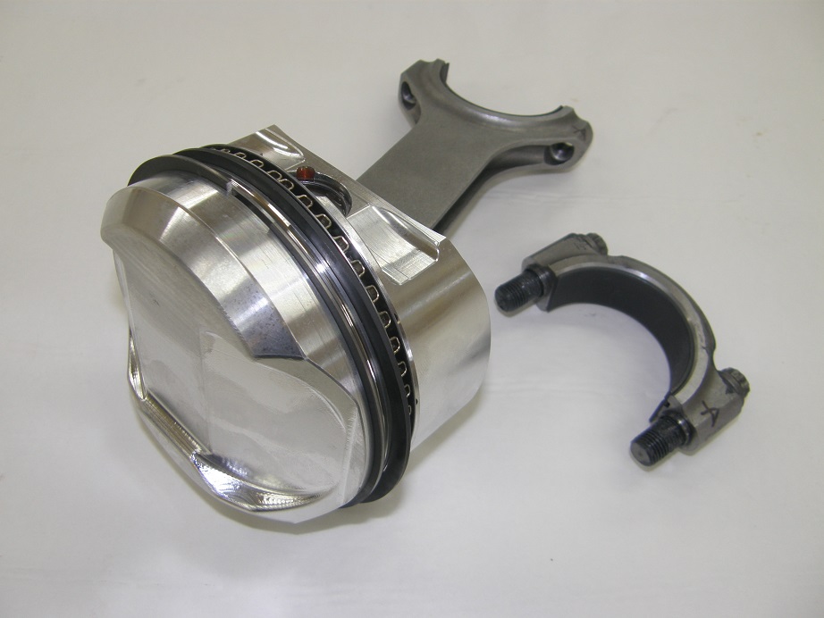
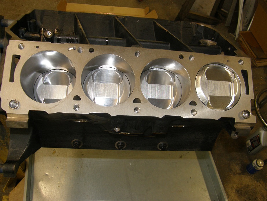
Regardless, at the beginning of July I was finally able to get the short block together.  Here's a couple of photos of a piston and rod assembly from this engine, and then four of the pistons installed in the block.  I'll put more detail in the FE Engine Dyno Results section, but basically this is a street motor designed to run on pump premium fuel, so compression was limited to 11.5:1.  With the cams we selected, this gave us a dynamic compression ratio of 8.25:1, which should be very friendly on pump gas. 


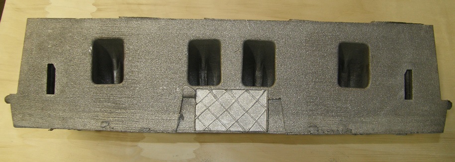
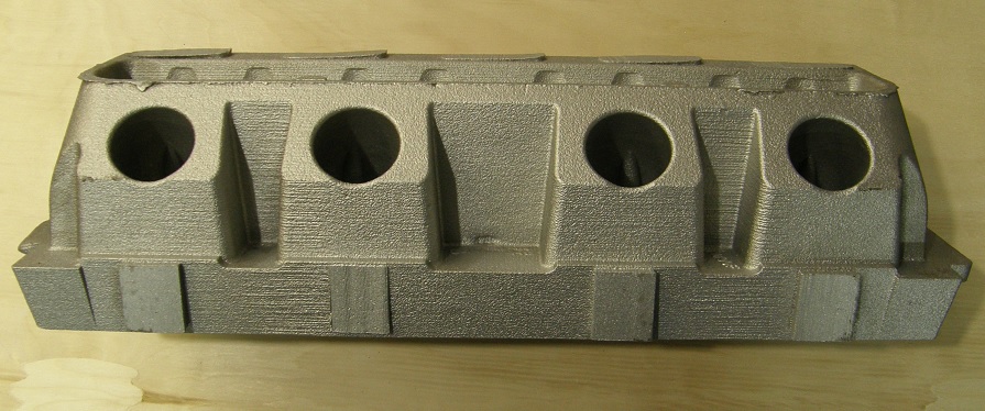
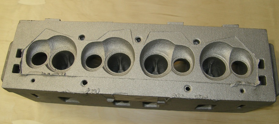
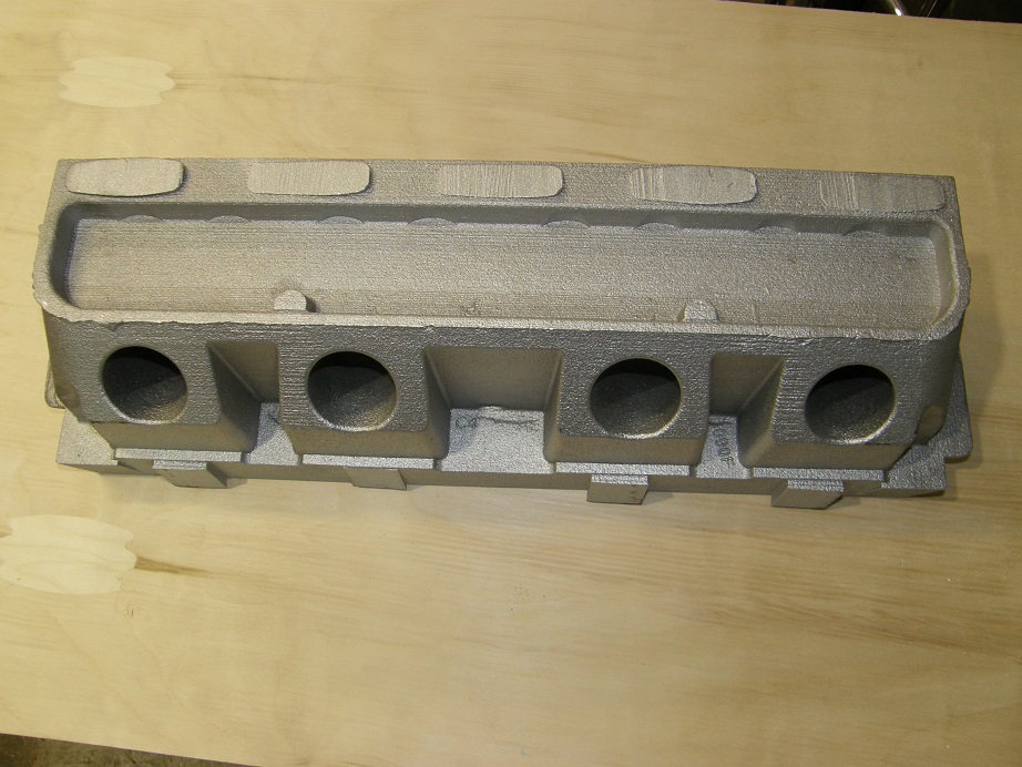
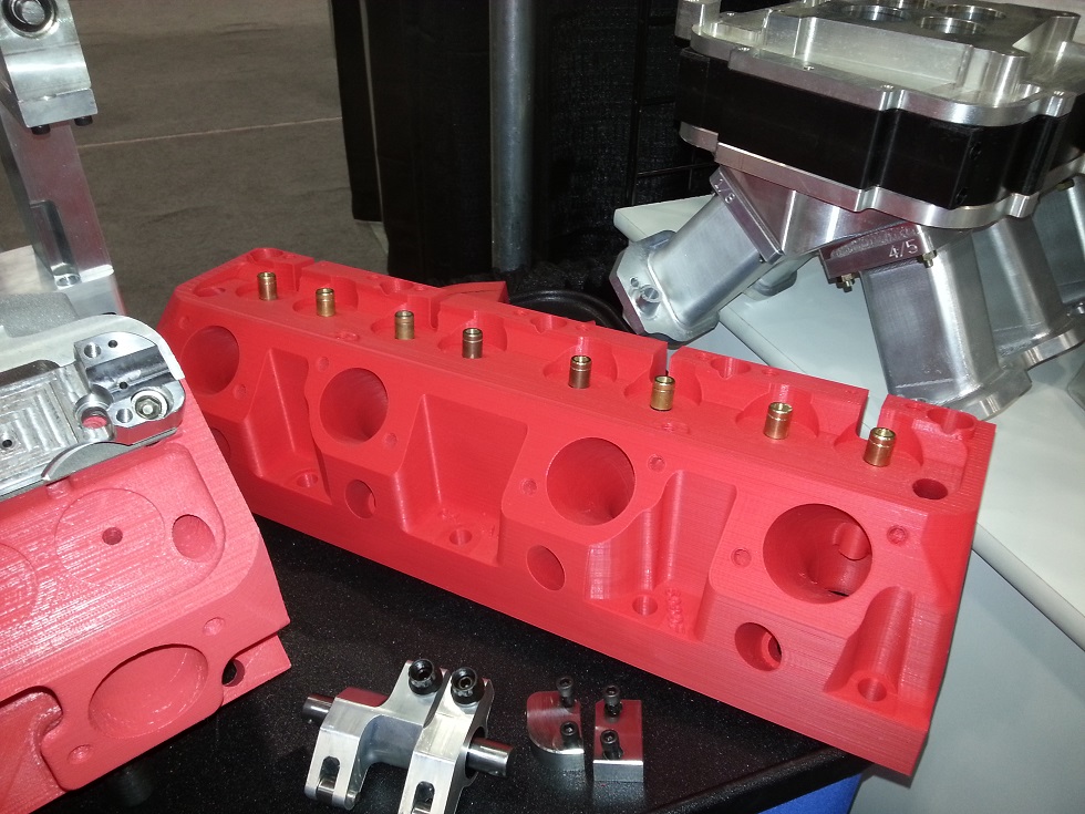
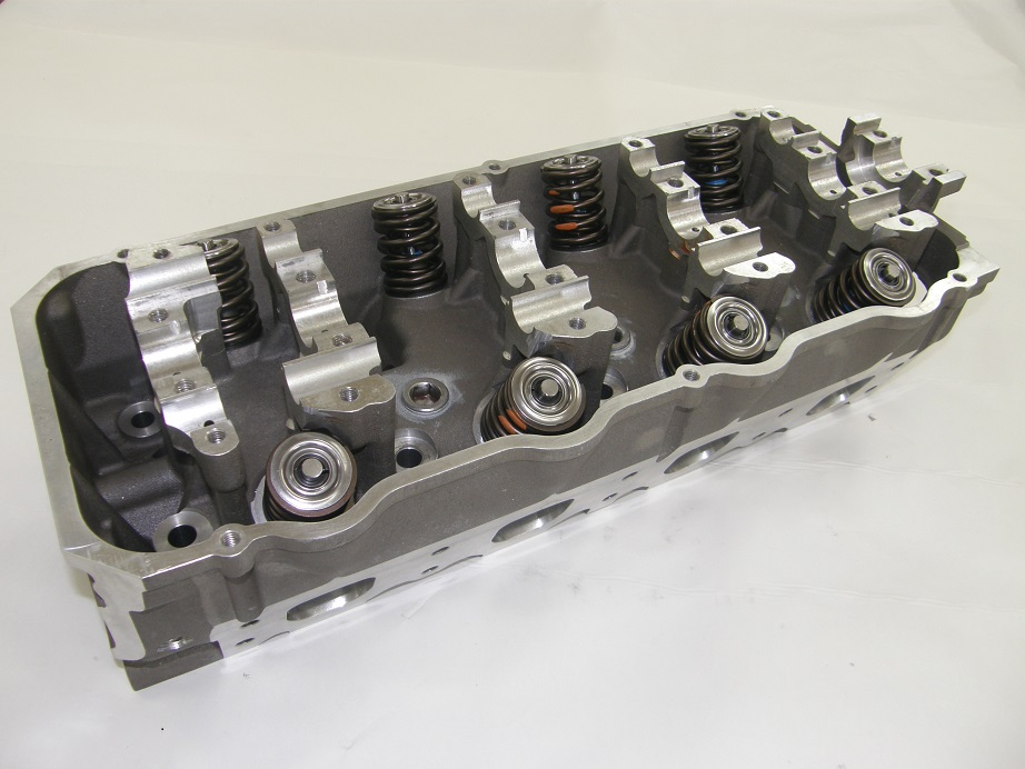
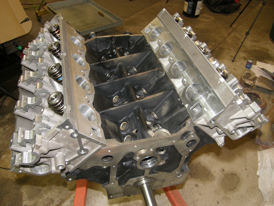
From a parts acquisition standpoint, the cylinder heads were the longest lead time item.  We were waiting for a set of Robert Pond's heads from a new casting batch that he was expecting, but when this was delayed, we managed to get a set of new Pond heads from my friend Kurt Neighbor in Ohio.  Because this was not a max effort build, we chose to go with the Ferrea hollow stem valves for the SOHC.  These don't flow as well as the Manley valves I've used before, or the Trick Titanium valves I have now, but they are reasonably priced and lightweight, allowing us to keep the valve spring pressure in a reasonable range.  After the valve job, the intakes flowed about 370 at 0.700" lift, and I fitted the heads with Comp 943 springs, set up with about 220 pounds on the seat and 585 pounds at peak lift.  Based on previous tests, these heads would have flowed over 400 cfm with the Manley valves, but would have required a heavier spring setup.  Here is a picture of a completed head, and then the heads mounted on the short block:


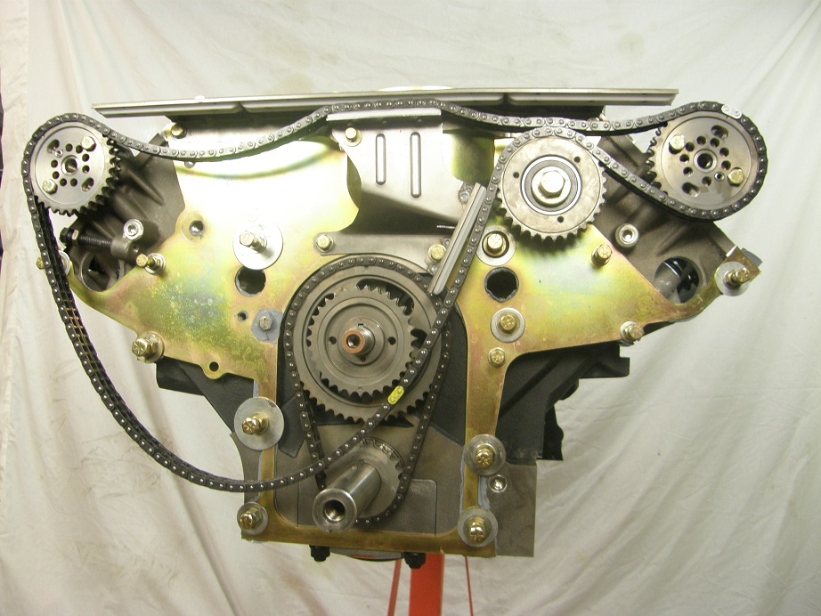
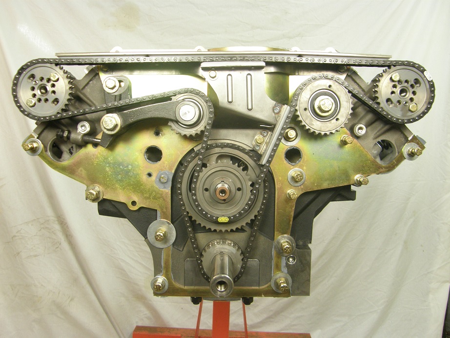
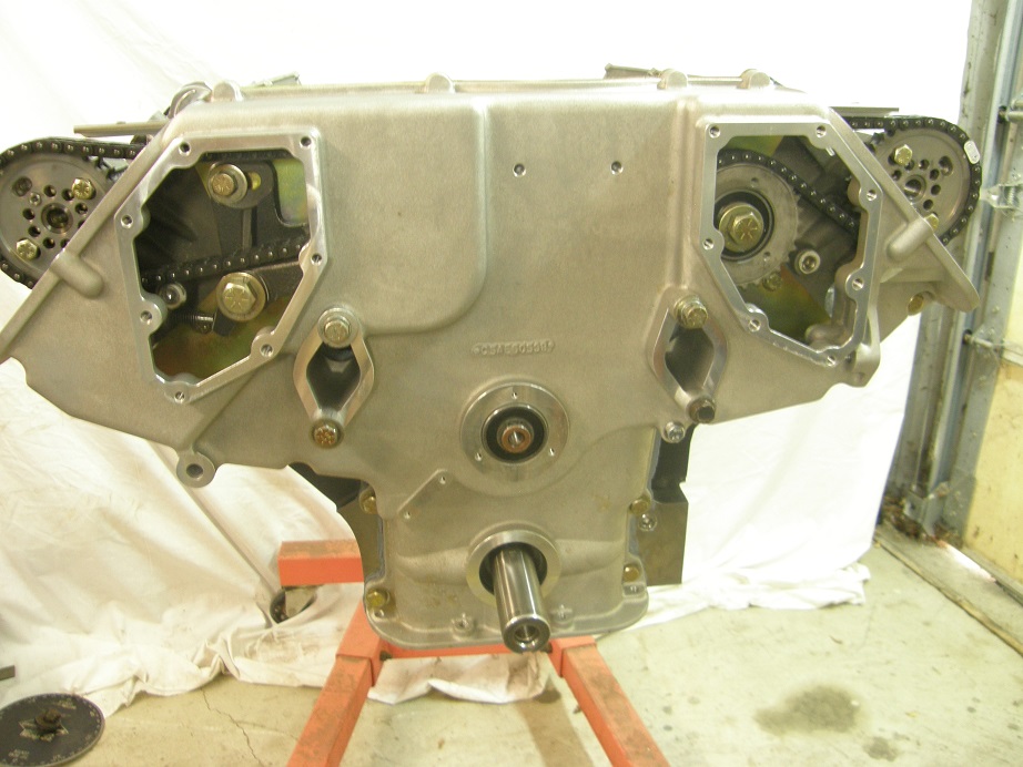
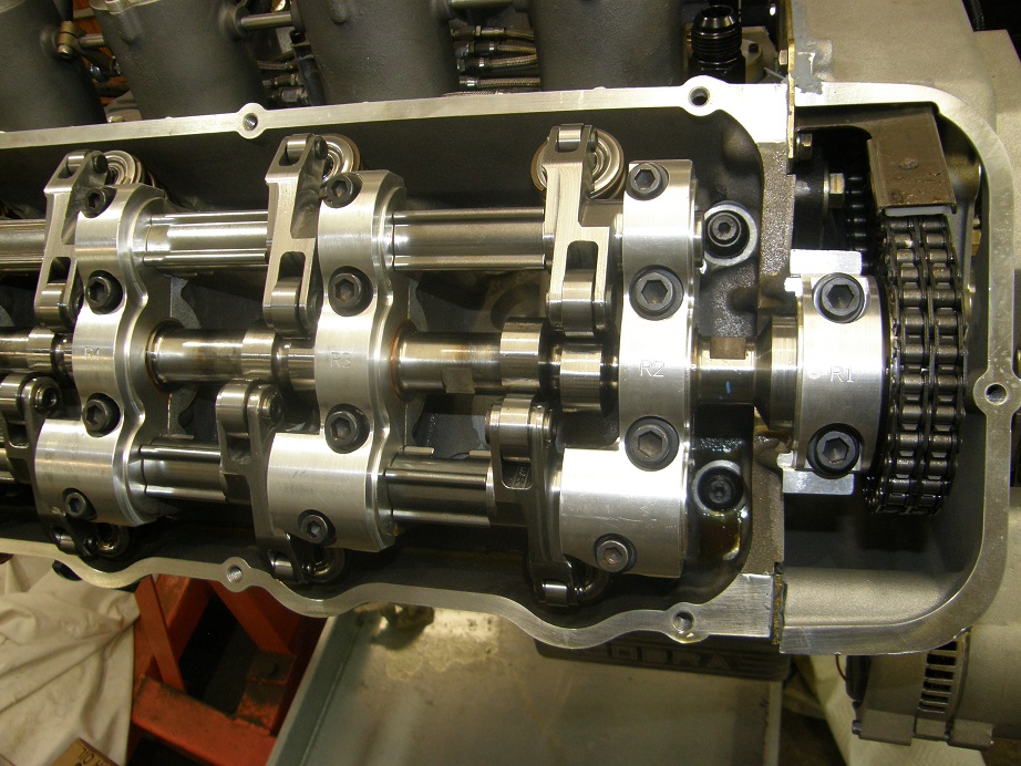
After the heads were installed I spent a few days getting the timing setup done.  This is a two step process, where the backing plate is installed and sealed to the heads and block, the sealer is allowed to dry, and then the timing setup is installed, and then finally the front cover.  I checked piston to valve clearance after mocking up the timing setup, and was surprised by how much there was, over 0.200" on the intake and at least 0.170" on the exhaust.  With the cam timing varying due to chain stretch, you'd like to have as much clearance as possible, so this was a great result.  Finally after getting the timing setup done I installed the front cover, and was really surprised at how well it fit.  I'm used to fighting with these things to make them go together at this point, but this front cover just slid right into place with no drama at all.  After buttoning it all up, I was very confident that it would be leak-free.  On the dyno, of course, it turned out that my confidence had been unwarranted  :(  More on that later.  Pictures below show some of the steps of assembling the timing setup and front cover:


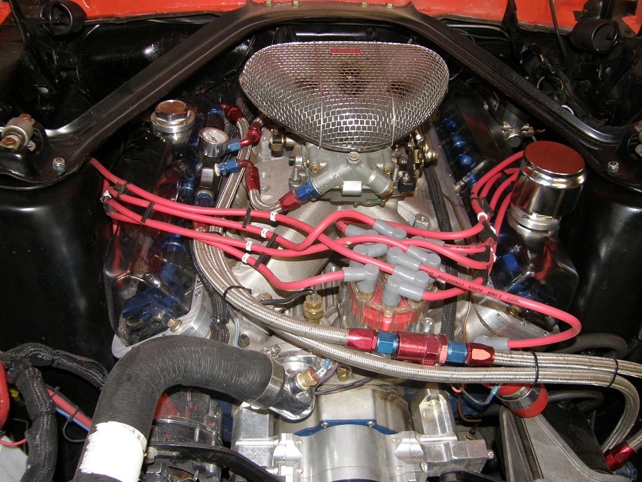
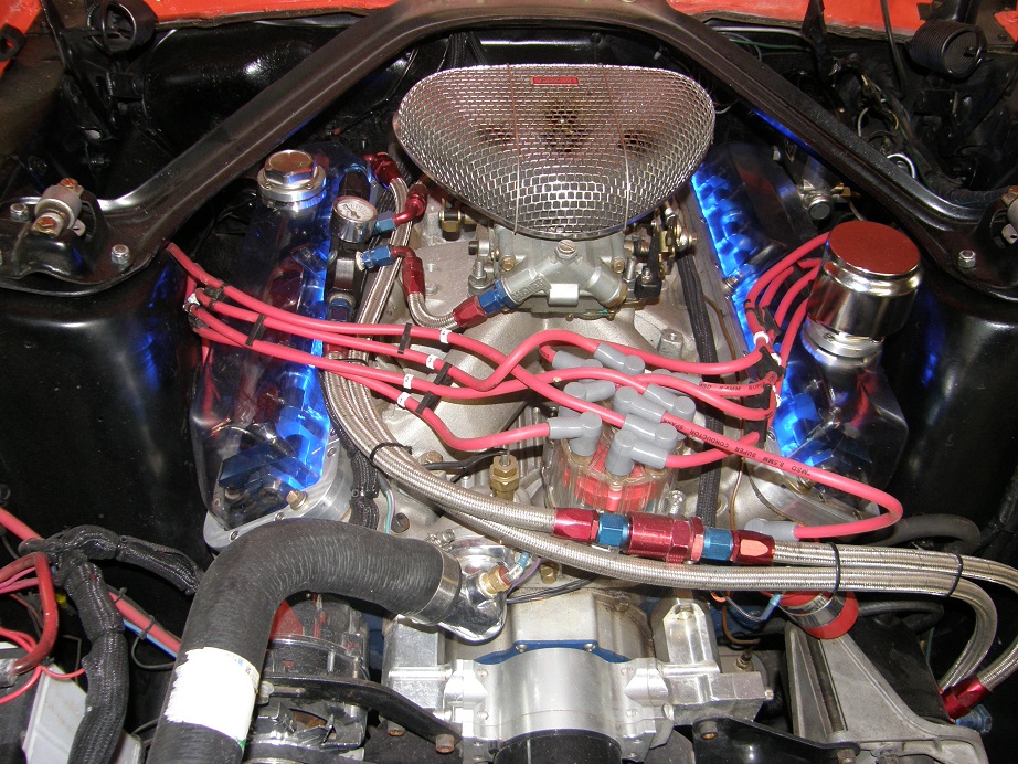
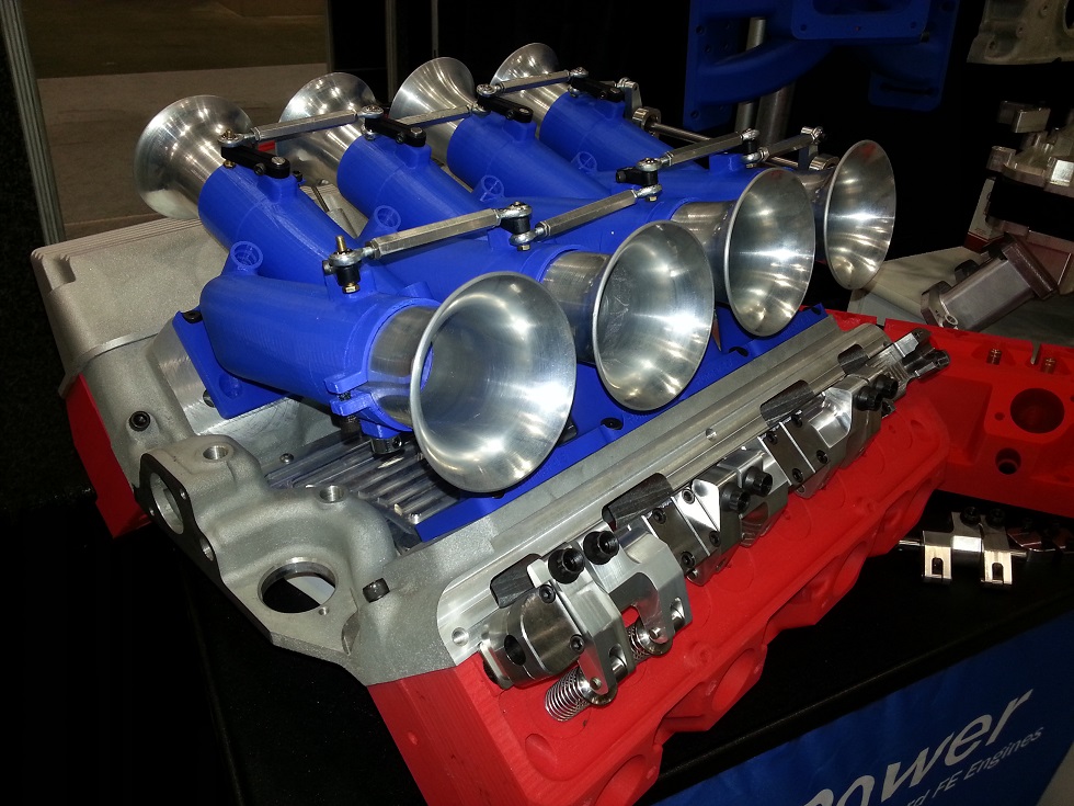
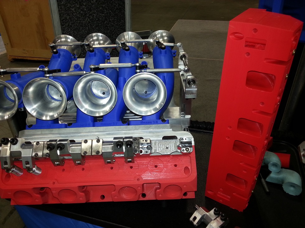
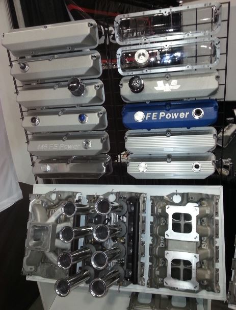
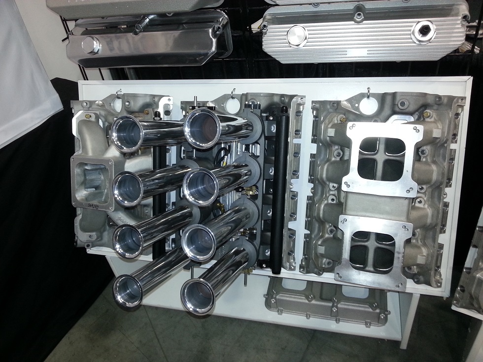
For induction, my friend wanted to go with a setup similar to the one I used on my 64 Galaxie in 2009, which is the Hilborn injector setup converted to EFI.  This setup made lots of power and was very easy to handle in normal street driving applications, plus of course the eye appeal can't be beat.  He purchased the base Hilborn mechanical injector setup and gave it to me to convert to EFI.  This involved machining the Hilborn manifold to accept EFI injectors, making up fuel rails to match the manifold, machining brackets that bolt to the base of the Hilborn setup and support the fuel rails, machining a bracket to mount the fuel pressure regulator, fitting the supplied throttle position sensor to the Hilborn manifold, and finally machining a vacuum box, where a vacuum line from each intake runner feeds in to a common volume.  From this volume, you can get a stable vacuum signal for use by the EFI system; if you try to use just one of the runners for this signal, there is too much pulsing and it will lead to erratic control by the EFI system.  The Hilborn setup with the modifications I made is shown in the photos below:


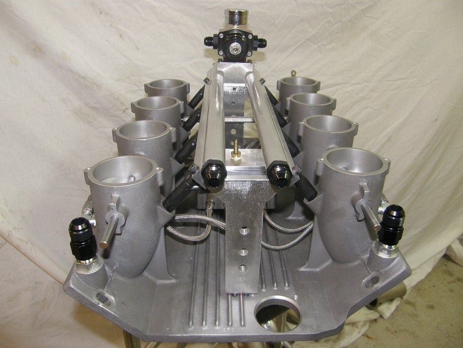
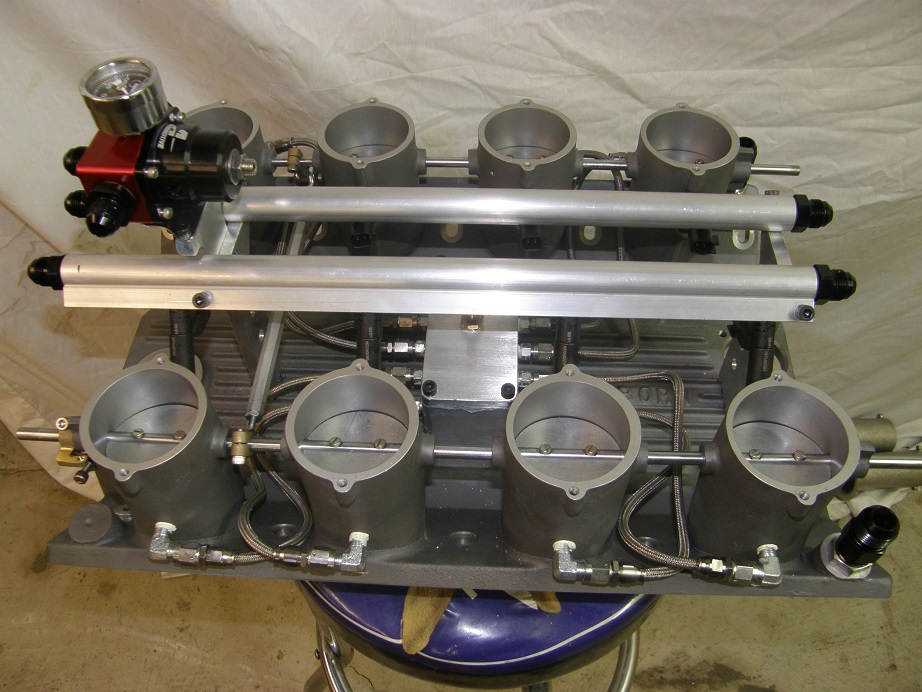
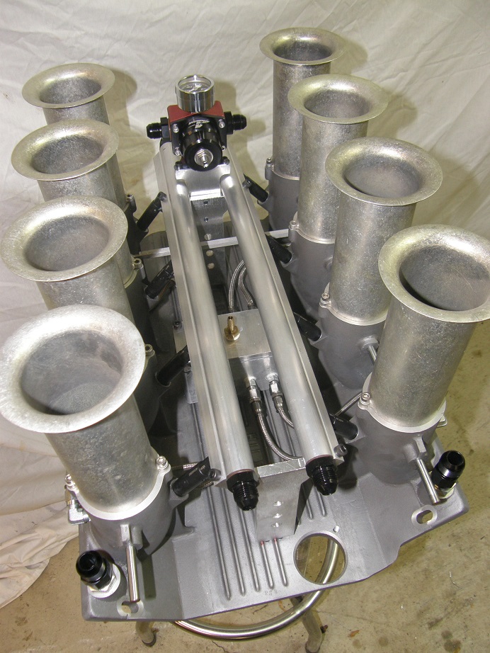
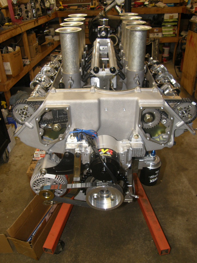
After mounting the HIlborn setup on the engine, it looked something like this:


Last step was to install the valvetrain.  The cams we selected for this engine are Comp Cams grind 8594 on both intake and exhaust, with a 112 LSA.  These cams have a 300 degree advertised duration, 277@0.050" lobe lift, and 0.723" gross lift with a 1.3:1 rocker arm ratio.  This is probably equivalent to about a 265@0.050" lobe lift wedge FE cam, given the difference in rocker ratio between the SOHC and a wedge engine.  For rocker arms, we selected my new FE Power SOHC rocker arms.  If you have read about my Drag Week exploits with these engines, you know all about the problems with rocker arms I've had, all related to the fact that the needle bearings in stock and aftermarket SOHC rocker arms rely on splash oiling for lubrication, and at low engine speeds and during idling, there is not enough splash to keep the needle bearings lubricated.  So, they fail, with somewhat disastrous consequences.  My new SOHC rockers do away with the needle bearings in favor of a bushing, and they are designed to provide direct, full time pressure oiling to the bushing.  They should last as long, or longer, than any bushed roller lifter with a similar system; the Morel Black Mamba lifters come to mind. 

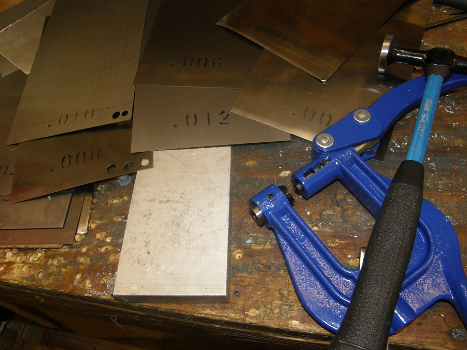
Although I plan to do some of these SOHC rocker arms with normal adjusters, my first versions use a roller tip to decrease weight over the valve stem, and avoid the scrubbing action of the adjustable tip across the valve tip, which Bill Conley has shown can cause excessive heat buildup.  Back in the day, this was done with lash caps of varying thicknesses, but I didn't have access to any way of grinding the lash caps to the proper thickness.  So, when I had first assembled the heads I had mocked up the valvetrain, then cut the valve stems so that with the lash caps and rockers installed, lash would be around 0.030" to 0.040".  Then, after getting the engine all assembled, I punched out steel discs, 5/16" in diameter and of varying thicknesses, and put them under the lash caps, to get the valve lash into the 0.020" range.   The punch I bought was a cheap one from Eastwood, and the metal circles that came out needed to be hammered flat, but after installing them I was able to get the lash right where I wanted it.  The pictures below show the punch tool and shim stock I used to get the lash set up correctly, then some photos of the valvetrain:


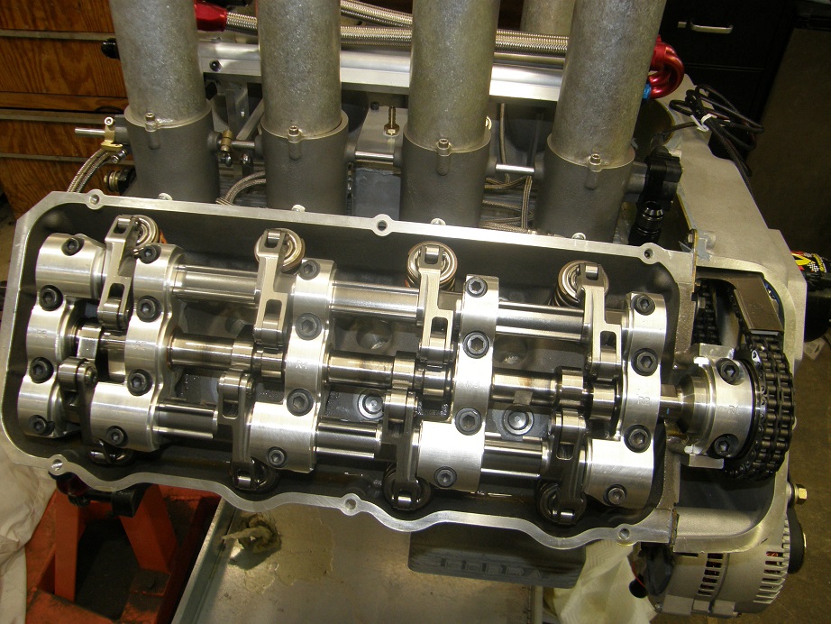
By the way, I have heard some reports that the Pond SOHC heads don't clamp the rocker arm shafts like they should; that if the pin that holds the shaft in place fails for some reason, the shafts can come sliding out.  I was prepared to machine 0.010" off the ends of the caps on these heads if I found that problem, but that was not the case here; as delivered, these heads clamped the shafts very securely, so no issues with that.

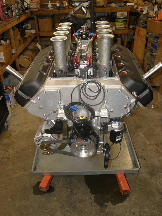
I finally got the engine all buttoned up last weekend, here's a picture:


Last Sunday night I got it installed on the dyno and completed most of the mechanical hookup on Monday.  Tuesday, I spent the entire day wiring up the EFI system.  This engine is similar to my race engine and the dyno mule I did last year, with full sequential fuel injection featuring a crank sensor, a cam sensor, 60 pound Ford injectors, and 8 individual coil packs.  In order to do a neat job wiring it all up, I mounted some of the required electronic parts on a board, and put them on the back of the dyno stand.  The picture below shows this board with two MSD capacitors that function as noise filters for the EFI setup; electrical noise is the enemy of EFI, so these caps ensure a clean power supply to the EFI box, coils, and injectors.  There are also three fused relays (one for the EFI box, one for the injectors, and one for the coils), plus an Innovate Motorsports wideband oxygen sensor controller.  And of course, the MS3-Pro EVO fuel injection system.


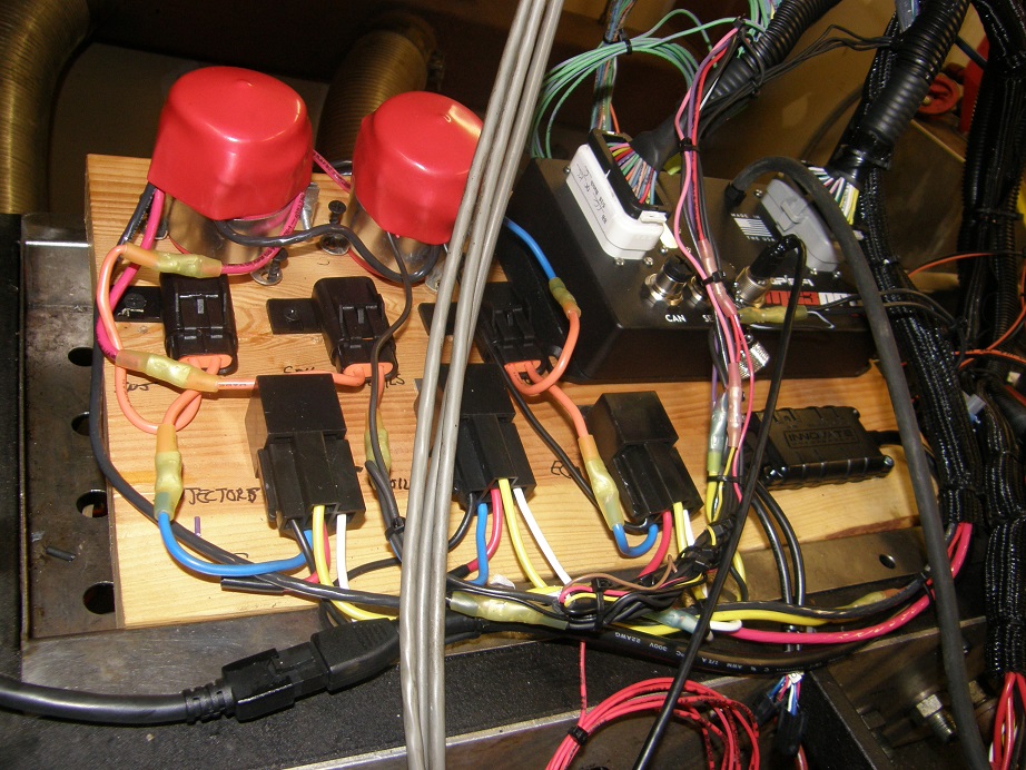
Note that in this picture, the three gray wires in the foreground are dyno related and not related to the EFI system.  Also a USB cable is attached to the MS3-Pro, and a vacuum line from the vacuum box on the intake manifold is also connected to the MS3-Pro.  The two large cables coming out of the MS3-Pro go to the coils, fuel injectors, and all the sensors.

Finally late on Tuesday night I got the last of the wiring done; I had not had time to make up the spark plug wires and we were going to dyno on Wednesday, so I figured we could just make them up in the morning. 

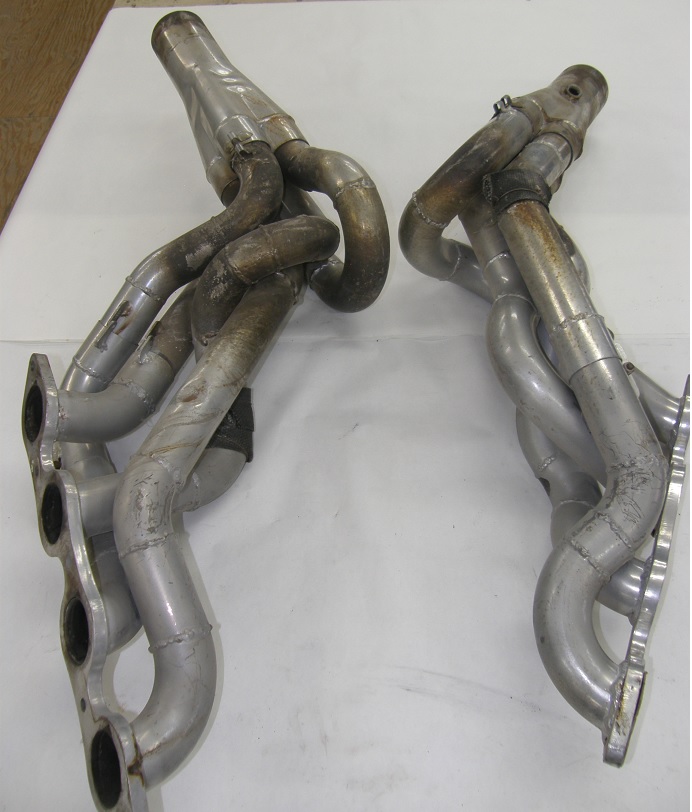
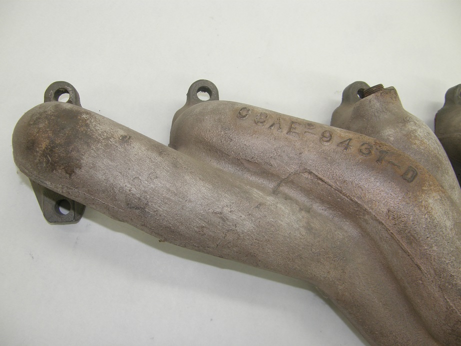
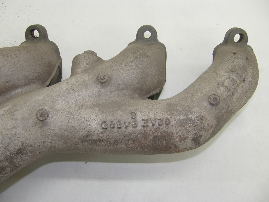
Some dyno session go easily, and some don't.  This one did not.  Wednesday morning my friend arrived, with his headers and engine mounts which we thought we might use.  However, test fitting the headers showed some obvious fit issues, so we decided to use my dyno headers instead.  After getting them installed, we got to work on making up the plug wires.  The SOHC uses a special grommet that fits over the plug wires and keeps water out of the spark plug tubes, so these have to be slid on to the plug wires before you put the ends on.  This turned out to be a huge pain, and very unexpected, because I'd never had an issue with these before.  The plug wires just didn't want to go through those grommets.  Maybe the rubber was too hard, or the hole in the grommet was too small, or something, but in any case it seemed like we spent hours working on this.  Finally what seemed to work the best was running a drill through the middle of the grommets to take out some of the rubber; then the wires slipped through fairly easily.  In the end it was after noon before we finally got the spark plug wires installed.

Next up was some computer issues.  My friend had brought his son's laptop, which uses Windows 10.  I don't have a Windows 10 computer, so I'm not familiar with the setups, and after hooking it up to the EFI box, I couldn't get the communication link between the computer and the EFI box to work.  My friend did a search online and we figured that out fairly quickly, and I uploaded a starting tune into the MS3-Pro.  After getting the software configured to my satisfaction, I tried to start up the dyno computer.  Unfortunately, it was dead.  I had smelled some burning electronics a few days earlier, and was suspicious of the dyno computer, but it had been working OK on Tuesday.  Wednesday, it failed completely.  So, no dynoing the engine on Wednesday.  We decided to start it anyway, and after correcting an error in the MAP sensor setup, the engine fired right off and sounded pretty good.  We played around with it a little on Wednesday, but quit about 5:00 PM.  I needed to get the dyno computer fixed, and resolve a couple of other problems, including an oil leak at the front cover, and also a water leak by the front bolt of the Hilborn manifold.  The oil leak was a surprise, because the front cover had installed so nicely, but there are a couple of large gaps between bolts on the left side of the front cover, and these engines can be prone to leaking there; that is where the leak was coming from.  We also had an oil leak at the left front of the intake manifold, but that was easily sealed up.  However, the Hilborn manifolds are FAMOUS for leaking water at the front bolts, so if you install one of these be very careful when sealing it.  Despite my best efforts we still had an occasional drip of water coming from that front bolt on Wednesday.

The dyno computer was a concern.  Superflow doesn't support the 901 dyno anymore, and the dyno software will not run on any operating system past Windows XP.  So, you can't just transfer the software to a new computer.  And Superflow wants some exorbitant amount of money, more than $30,000 if I recall correctly, to update the dyno software so it will run on Windows 7.  So if the dyno computer failure had been the motherboard or disk drive, there was no fast way for me to fix it.  Fortunately, late on Wednesday night I plugged in a spare computer power supply, and the computer came right up, so that problem went away fairly quickly.  On Thursday I worked on getting the front cover leak fixed and the water leak sealed up, and also addressed some issues with the throttle linkage and the oxygen sensor, which had not been reading correctly. 

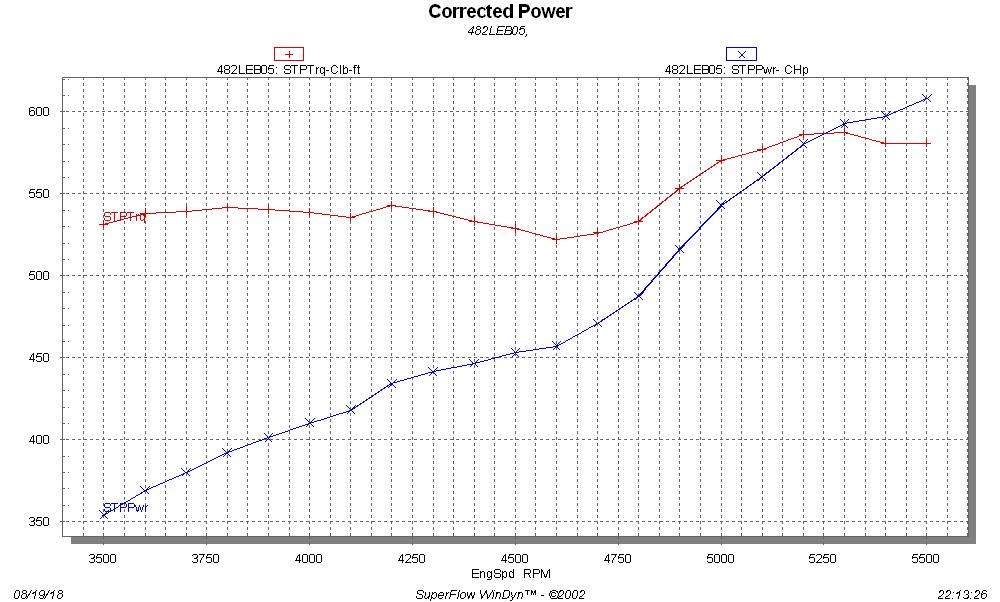
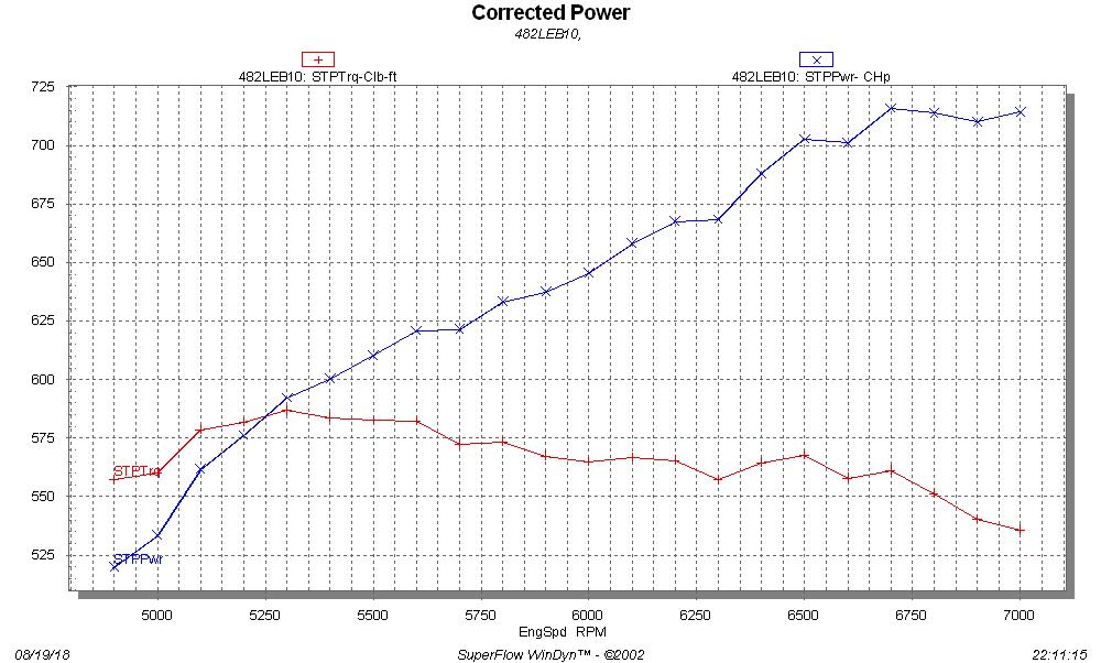
Friday afternoon, we tried again, and this time had pretty good luck.  Before my friend arrived I worked on getting the engine to idle and transition into the dyno pulls smoothly.  My 585" SOHC would idle at about 750 RPM with the Hilborn setup, and I was able to get this engine down to 750-800 RPM, but it felt better at around 900 RPM so that's where I left it.  The O2 sensor hooked to the EFI system still wasn't working right, but eventually this was traced to an intermittent power connection to the Innovate Motorsports O2 sensor controller; once that was corrected, the O2 sensor readings from the two dyno oxygen sensor and the oxygen sensor connected to the EFI system were very close.  I ran one checkout pull from 3000 to 5000 RPM before my friend arrived, and the engine sounded great and was making good power.  After he arrived, it was a simple matter to advance the RPM range and tune the air/fuel system using the three O2 sensors and the VE table on the computer.  In the end, the engine sounded great and made about 587 lb-ft of torque at 5300 RPM, and 715 HP at 6700 RPM.  A low RPM pull and  high RPM pull are shown in the graphs below.  Note that this engine wants to rev even higher, and it would not surprise me if it kept making 700+ HP well past 7500 RPM. 


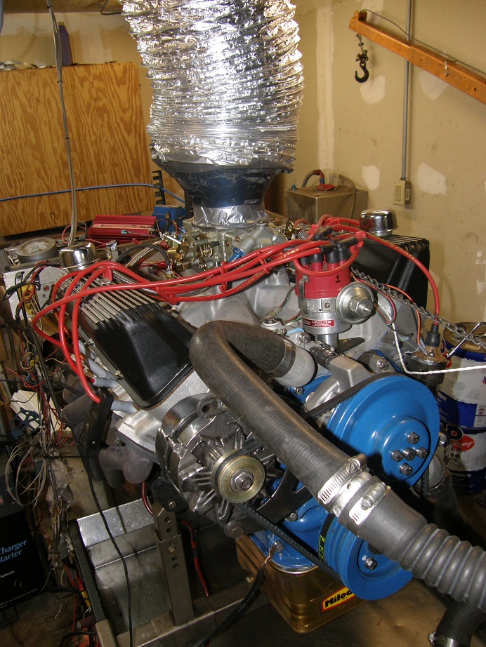
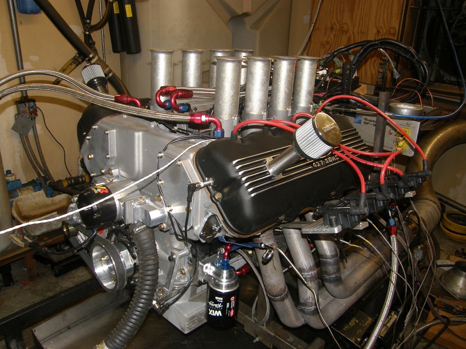
Here's a picture of the engine on the dyno:


I have a video of one of the dyno pulls, so I will post that in this thread a little later.

Lastly, as some of you may noticed we had a little dust-up over correction factors on the dyno a few weeks ago.  The numbers in the graphs are corrected to standard dyno conditions, which are 29.92" of mercury (sea level), zero humidity, and 60 degrees Fahrenheit.  For this dyno session, the correction factor was 7.3%.  Inlet air temperature was 86 degrees F, barometer was 29.18 inches of mercury, and vapor pressure was 0.60.  There is no inertia correction on this Superflow dyno, but all tests were run at a speed of 300 RPM/second.

More details on this engine are in the Dyno Results board, see the link below.  Any questions on these results, please let me know - Jay

http://fepower.net/simplemachinesforum/index.php?topic=6370.0

Pages: 1 ... 3 4 [5] 6 7 ... 25