Show Posts

This section allows you to view all posts made by this member. Note that you can only see posts made in areas you currently have access to.


Topics - jayb

Pages: 1 ... 23 24 [25]
361
Monday this week on my lunch break I put in a call to Fatman Fabrications to ask about the issue with how the front struts I purchased fit on the spindles. Basically they told me that the kit was designed to be used with stock components, and that aftermarket components may not work properly with the kit. They singled out the Strange Engineering struts I had as a potential problem. This really didn't make any sense to me; if the original '79-'93 Mustang spindles had wider ears than the '94-'04 spindles, how could Strange offer a strut that fit a narrower set of ears? I suspected that maybe there had been a change to Mustang spindles somewhere in the mid 1980s that the guys at Fatman didn't know about, because my Strange struts were not specified for '79-'93 Mustangs, only from '87-'93. Unfortunately I was stuck with them, because they'd had to be modified slightly in order to fit the lower spring mount that came with the Fatman kit over the strut tube. I resigned myself to the fact that I had wasted my money on these struts. I didn't want to buy stock Ford struts for this car, because I wanted a 90/10 style strut for a drag race oriented suspension. On Monday night I went looking through the Summit web site, and found some Lakewood 90/10 struts for '79-'93 Mustangs. I went ahead and ordered these, figuring I could return them if they also had the mounting bracket for the narrower ears on the spindle.

Late in the evenings this week I continued to read up on web sites, so not a lot got done on the car project. Thursday my new Lakewood struts showed up from Summit, so I anxiously took them out of the box on Thursday night to see what they looked like. Sure enough, they came with the wider spacing between the brackets, so they would work as I wanted them to in my application. However, they also came with their own set of spacer plates, so that they would bolt onto the narrower ears of my spindle if the plates were used. Since these struts were specified for '79-'93 cars, I am now fairly certain that a change to the mounting ears on the spindles was made by Ford in 1987, making the ears narrower and causing my problem with the '87-'93 Strange struts.

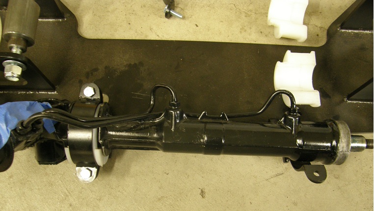
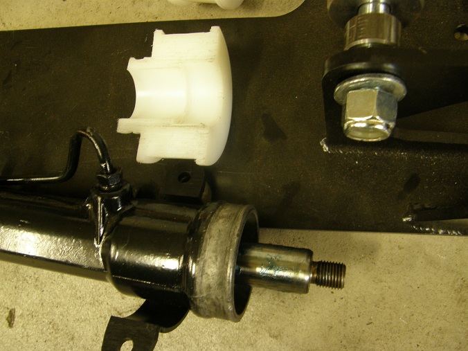
Friday night around 9:00 I got back out to the shop to get going on the car project again. I started out making the adapter plates I needed to allow tilting the strut outboard from the original shock tower locations. Steve and Jerry were going to come over on Saturday night for another barn night, and I wanted to be able to put the whole front end together when they were here, so I needed to get these plates done. Here's a picture of one of the struts with the pair of plates installed:


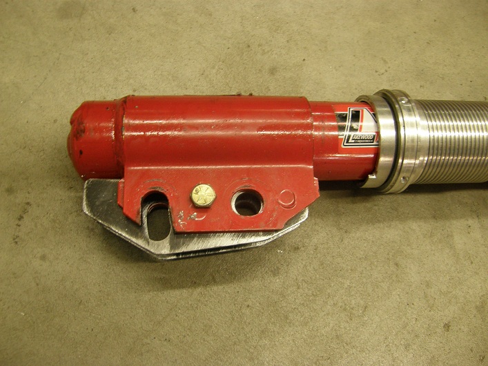
I got one pair done on Friday night, and the other pair done on Saturday morning, and spent the rest of the day on Saturday afternoon finishing up the welding on the quarter panels, trunk drop downs, and outer wheelhouses on the passenger side of the car. I knew that if I didn't have that done by the time Steve and Jerry came over, they would be merciless in their verbal abuse of me.

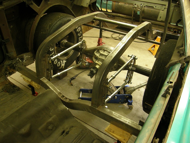
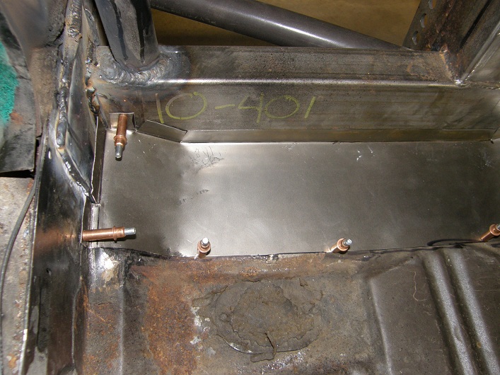
When Steve and Jerry came over, I had finished the quarter panel and had started working on a patch panel that would go between the original stock floor of the car and the back half crossmember. I managed to finish fitting it up just after they arrived, so Jerry grabbed the wire feed and began welding it in place. Steve took over the TIG welder to finish some TIG welding that needed to be done on the front frame support bars and the back half area, while I started working on getting the struts installed with the spacer plates I had built earlier. Steve finished up with the TIG welding fairly quickly, and started trimming around the front area of the car, where we had used the plasma cutter to cut away the shock towers and inner fenders. He used a cutoff wheel to make those cuts nice and clean, and then built a T-shaped 1/8" steel plate to cap the shock tower area where we had cut it off with the plasma cutter. Meanwhile I had figured out how I wanted to mount the upper struts to the front frame support bars, and had used a combination of the brackets in the Fatman kit and my own custom brackets to get the upper struts positioned properly. Jerry finally finished up with the sheet metal welding on the floor (which was a lot of welding), and came up and tacked the upper strut mounts in place.

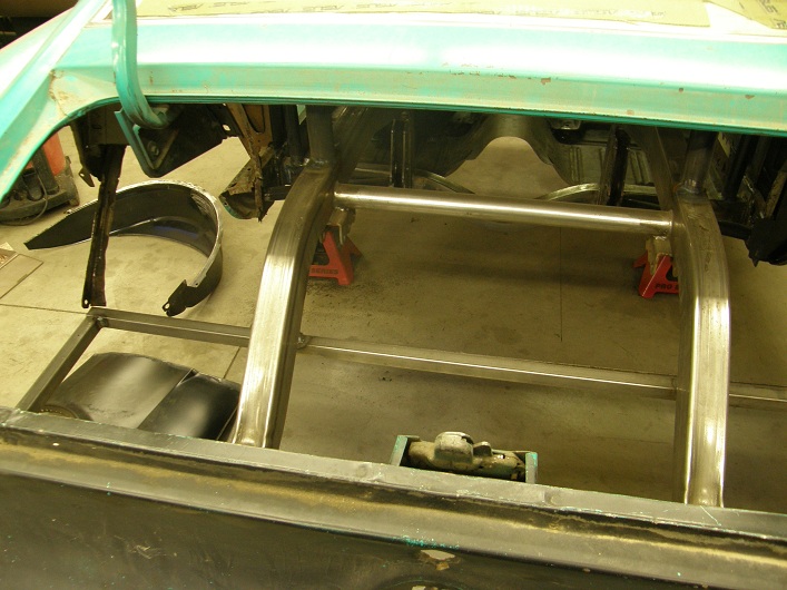
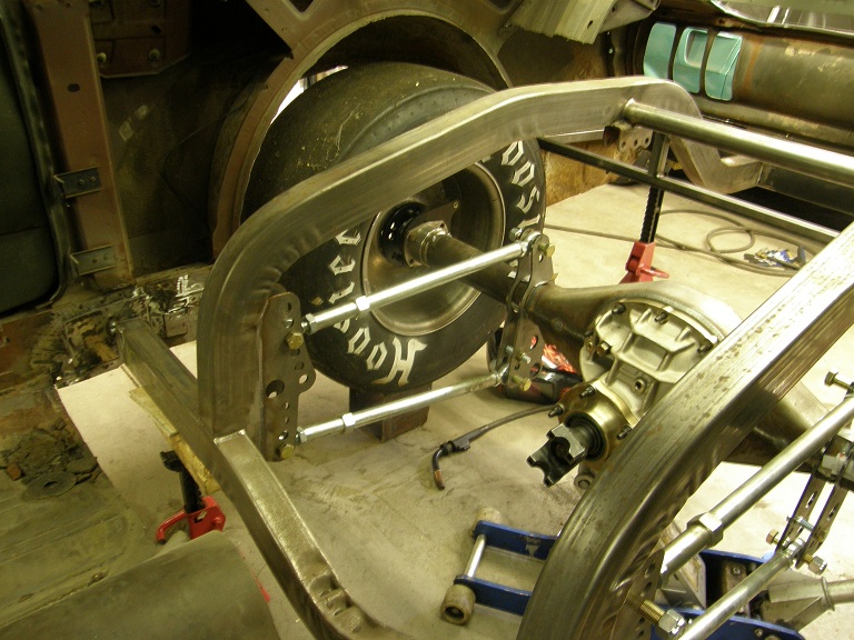
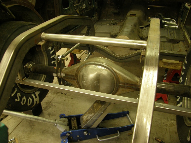
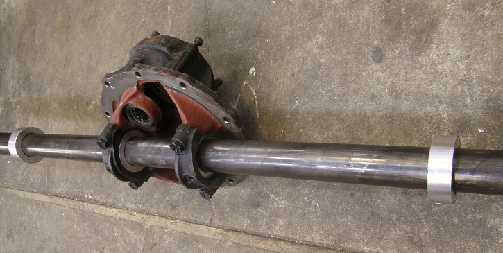
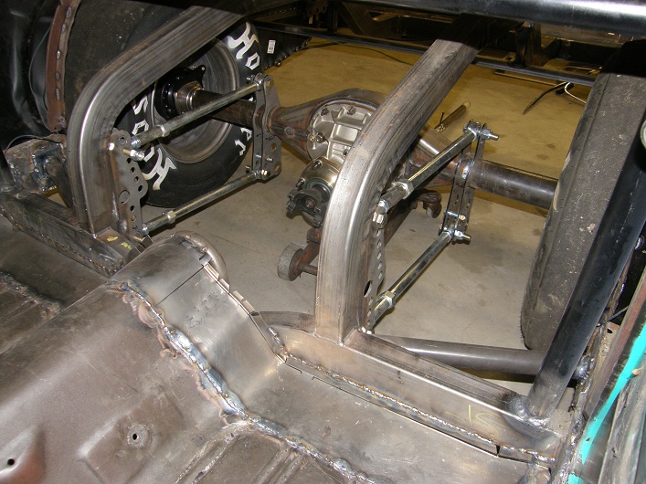
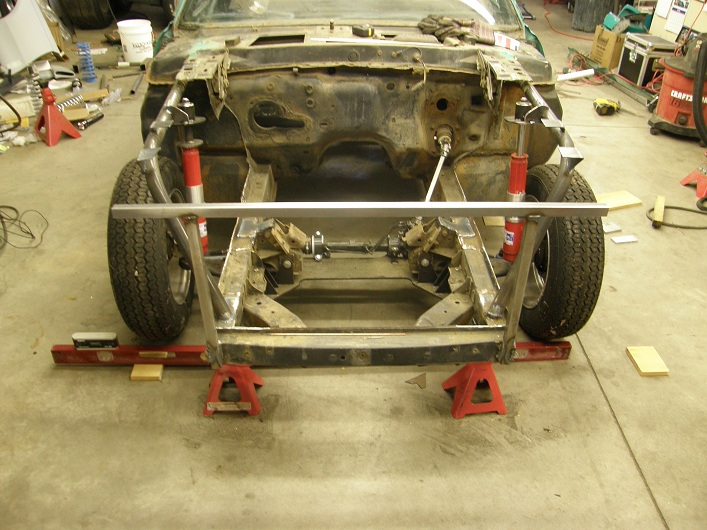
At the end of the night we slid the Wilwood brake hubs onto the front hubs, re-installed the four link, rear axle housing, and rear wheels and tires, and also bolted the front tires on the car. Finally, I took the car down off the jack stands and supported it at ride height so we could see how it all looked. Here's some pictures, starting with the sheet metal patch at the back of the floor:


Everything was starting to look pretty good! Jerry and Steve took off, and I had the afternoon on Sunday available, so I fell asleep thinking about what else I could do to the car on Sunday afternoon.

Sunday afternoon I was back out to the shop. I had decided that I wanted to put the front end fiberglass on the car to see how it looked. The Branda fiberglass had been leaning against the garage door for over a month, so I was anxious to see how it looked when installed.

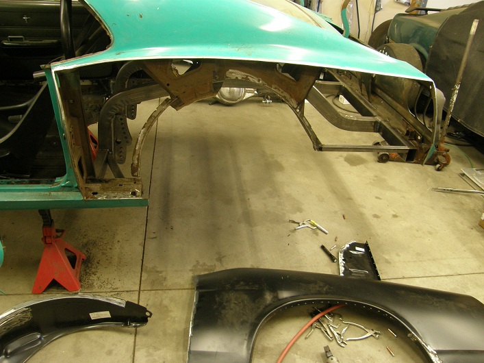
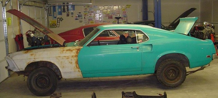
As usual, the fiberglass parts presented some fitment issues. Wrestling the front fenders into place so that they would actually bolt up to the mounting points towards the back of the fender was rather challenging, but with a certain amount of convincing they eventually went into place. Getting both fenders installed and looking about right took a couple of hours. Next I started looking at installing the headlight buckets and the front fender trim, and it was clear that some trimming of the fiberglass pieces would be required. I got the passenter side parts installed, and then for fun I laid the hood in place on the car, and took this picture:


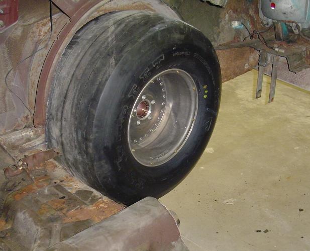
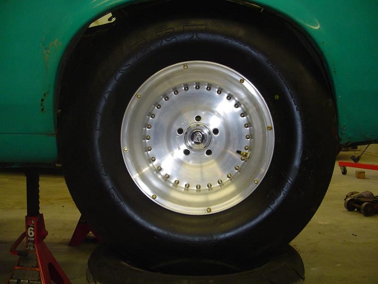
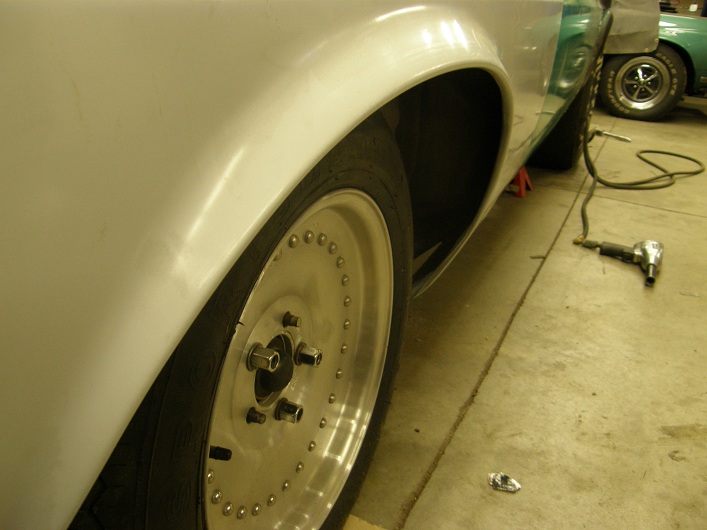
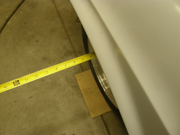
I was standing around enjoying how the car looked like this, when I noticed something rather disturbing. The front wheels were moved way, way inside the fenders! Standing back a little and looking at the wheel and tire position, the car looked like an old funny car, which was definitely NOT the look I was going for. I measured the distance from the fat part of the tire to the outer fender, and it was four inches! Here's a couple of photos:


I wondered if this was a wheel offset issue or a front suspension track width issue. Given all the issues I'd had with the Fatman kit, I was afraid I knew the answer. The car looked like crap with the wheel in this position, and I resigned myself to investigate this issue in the coming week. I left the shop tonight pretty disappointed; we will see what the next week brings.


362
Monday and Tuesday this week I had the day off from work, and the Christmas festivities were over, so I spent two solid days working on the Shelby clone project. The only interruption was to send the book manuscript on disc off to the printer on Monday; hopefully I'll be able to get the printed copies by the end of the month.

Before I got started on the car today I called ATI. I still hadn't received the transmission I ordered earlier this month, and wanted to know if they could give me a schedule. It turned out that the Powerglide to FE bellhousing had not arrived at ATI from the foundry yet, and would probably not arrive until mid January. So, I will have to wait until then to see my new transmission.

In the shop this morning I decided on a change in plans. Rather than working on getting the new quarters and other sheet metal welded in place, I decided to work on finishing the roll cage instead. I figured that the roll cage would help strengthen the frame structure of the car when it was finally welded into place, and I thought that would be a good thing when I was welding on the sheetmetal. So I started with the roll cage on Monday morning.

In short order I had the passenger side roll cage front upright bent and tacked into place on the front hoop, and sitting on it's 6" X 6" plate on the floor. Next I started working on the sidebars that go from the front uprights to the main hoop, across the middle of the door opening. Here I had to stop and figure out how best to proceed, because the main hoop was positioned just behind the door openings, and the front uprights were positioned just ahead of the door openings. So, when I put in the sidebars, access to weld to outboard side of the sidebars was very limited because they were up against the interior panels of the car. I wasn't all that great at welding in confined areas, so I spent some time figuring out the best way to do this.

In the end I settled on the idea of welding in the sidebars across the door openings from the inside, and making these welds as solid as possible, 180 degrees around the tube where I had access. Then, since the sidebars were going to be configured as swing-out bars, I could cut them at the connection joint up near the main hoop on each side. Then, I could cut the tack weld between the front hoop and the front uprights on each side, and completely pull each front upright and its attached side bar out of the car. This would give me access to weld completely around the sidebars where they attached to each front upright. Then, I could pull the main hoop forward past the door openings(since it still had not been welded to the back half frame rails) to get access to the outside half of the sidebar stubs that had been welded to the main hoop, so they could be welded all the way around. Finally, the main hoop could be repositioned, the front uprights could be repositioned, the sidebars could be clamped together into alignment where they had been cut, and the front uprights could be welded to the front hoop.

This work took me most of the day Monday to get accomplished. I also had to add a gusset plate to the front upright / front hoop junction on each side, because the angle of the front uprights to the front hoop was pretty extreme. After I got the gusset added and everything welded from underneath, I pulled the 6" X 6" plates out of the way, pushed the whole cage back a few inches so that the main hoop was off the back half frame crossbar, and dropped the whole cage through the floor again so I could weld the top of the front uprights and gusset plates in place. After I was done welding, I took the opportunity to paint over the top of the cage bars with a chassis epoxy, since I wasn't sure that I would get this opportunity again. I finished the day by putting the cage back into its final position, and cutting the side bars down near the front of the door opening, where they would pivot open when finished, and then painting the rest of the cage where the welding had been completed.

Tuesday I worked on getting the front frame support bars installed. These bars run from the front cage uprights forward along the top of the fenders, and then bend down to weld to the front subframe up near the front end of the car. My plan was to cut the shock towers and inner fenders completely out of the car at some point, so these two bars had to run close enough to the front fender mounting points so that I could add tabs to the bars later for mounting the front fenders. Therefore I wanted the bars to run straight along the inner fenders at the top for a good four feet before they curved down to the front frame rails.

Also, the attachment of the bars to the front hoop was a concern. Where the bars would attach was ahead of the door opening, so I wouldn't be able to easily weld around the entire joint with the cage in the final position. I had thought about this already, which was why I hadn't welded the cage to the back half frame or the 6" X 6" plates yet. My plan was to tack the front frame support bars to the front uprights, and then pull the cage straight back so that the joint was exposed through the door opening, and I could easily weld all around the front upright to front frame support bar joint.

In order to do this I had to make sure that the front frame support bars went straight through the sheet metal to the front uprights. Where they had to go through, they had to penetrate the sheet metal of the car in two places, spaced about 10" apart. If they went through at an angle, it would be impossible to pull the rest of the cage straight back and get access to the joint for welding.

In order to make sure the hole for the bars came straight through the sheet metal, I tool a 1/4" diameter 12" long drill bit and lined it up from the engine compartment to aim straight at the driver's side front upright. The drill has a level on top, so making sure to keep the drill level, I drilled through the outside sheet metal, and then farther in through the inside sheet metal. Using these holes as a position indication, I used my plasma cutter to cut the holes in the sheetmetal, from the engine compartment side for the outside panel and from the interior side for the inside panel. Then I fed a test piece of chrome moly tubing through the holes, and made a few more trims with the plasma cutter, until the tubing would slide straight through and contact the front upright.

Next I bent up the driver's side front frame support bar, notched it to fit against the front upright, and trimmed it at the front of the subframe rail to fit on the top. I had to cut away the inner fender forward of the shock tower in order to get the bar positioned where I wanted it. I trimmed the bar to fit the subframe rail, clamped it in place, then climbed into the interior to weld it to the front upright from the inside. I repeated the whole process on the passenger side, then pulled the cage straight back and finished the welds through the door openings. Finally I pushed the cage back into its final position, and after double checking the position to make sure I had everything right, I welded the main hoop and the rear support bars to the back half crossmember.

This was another milestone for the car. I still had more welding to do on the cage attachment points, but now the cage was set in place and wasn't going anywhere. I was planning on finishing this work up on the weekend

Wednesday and Thursday I was back at work, but we had Friday off for New Year's, so after some family obligations in the morning I was back out at the shop. I started by welding the 6" X 6" plates to the floor of the car, and then welding the front uprights to the plates. This was a little tricky due to access issues, and I had to use a mirror behind the front upright tubes in order to see what I was welding around the back side of the tube. Fortunately, this isn't as tough as it sounds, and if you go in small increments it can be done; it just takes some patience. From there I built some 1/8" plate pieces to weld onto the front subframe where the front frame support bars welded on. Since the front subframes are just glorified sheet metal on these cars, I wanted to use the large 1/8" plates to spread the load on the subframes. After I tacked the front frame support bars in place up front I moved back to the back half frame rails, which were still only tacked in place. I removed the wheels, tires, and axle housing for access, and welded the back half frame rails securely to the rocker panels and the rear 2X3 rectangular steel tube that was welded to the taillight panel. Finally I cut two more short pieces of chrome moly to run from a different spot on the rocker panel back to the back half frame rails, for additional strength.

On Saturday I focused on the front end of the car. I wanted to cut the core support and inner fenders out, but before doing that I had to put a framework in place to support the front of the fenders and other front end pieces, plus the radiator. After an hour of thinking about the best way to do this, I decided on a simple framework made from 1" X 1" 16 gauge square tubing. As I was getting going on this Steve showed up with a couple of hours to help out. Between the two of us over the next couple of hours we got the square steel tubing welded in place, and also welded some tabs onto the front frame support tubes that were lined up with the holes in the inner fenders that the fender bolts went through. Then we used the plasma cutter cut away all the core support, inner fender, and shock tower sheet metal. This was an extremely cathartic experience for me; I have hated the shock towers in Ford Mustangs for years and years, but have never completely removed them from a vehicle. As we pulled the pieces away and threw them in the scrap file, it felt like a great weight had been lifted from my shoulders. Look at all that room! The cammer and the headers would fit in here with no problem now.

After Steve left, I decided that with the inner fenders and shock towers gone, I could mount the struts on the spindles and see what they looked like. Sure enough, as soon as I got back to the front end, things started going wrong again. The first thing I did was to try to fit the adapter plates included with the Fatman kit to the spindles. These are two pieces of 1/8" steel plate that act as spacers between the '94-'04 Mustang spindles and the '79-'93 Mustang struts, because the brackets on the bottom of the Mustang struts are spaced farther apart than the width of the ears that they bolt to on the spindles. The adapter plates in the kit came in pairs, welded together with a nut in between them. A jacking screw was threaded into the nut, to be used for camber adjustment by jacking the strut away from the spindle. Unfortunately, this assembly did not fit on the spindle; it was too narrow. This wasn't that big of a deal to me because I was going to replace this assembly with some custom plates anyway, but I wondered what kind of a jig they had used to build something that didn't fit. Next I grabbed one of the struts, which had been sitting in the box next to the car for the last month or so, and test fit it. I figured that even if it was loose it would give me an idea of what I needed to do with the strut upper mounting point. However, I was surprised to see that the strut fit perfectly onto the spindle! There was no adapter required! This would have been fine, except that I was relying on using those adapter plates to allow pivoting of the strut so that the upper strut mount could be moved outboard. Essentially, I couldn't use the strut as it was.

This was another big disappointment, and I didn't really know how to proceed. I plan to give the people at Fatman a call on Monday and ask about this. I left the shop a little discouraged on Saturday night.

Sunday I decided to leave the front suspension work again, and worked at getting the sheet metal welding done on the quarters, trunk drop downs, and outer wheelhouses. The driver's side went along with no trouble; I kept a wet rag next to the panel as I was welding, and just went around and around each quarter panel, welding a button at a time, until I had the seam completed. Underneath I welded the outer wheelhouse and trunk drop downs in place after some additional trimming of these parts, and plug welded throught the quarter panel lip to the outer wheelhouse. On the passenger side, I decided I wanted to reposition the quarter panel just a little, so I drilled some more holes, took out Steve's sheet metal screws and put in some Klecos in slightly different locations to move the panel an eighth inch here and there. Finally I got to welding, but kind of petered out by late afternoon without finishing the welding work on that side. I'll get to it later. I went inside because I need to start getting going on building a web site to advertise my book. With the book at the printer the clock was running on this, and I didn't have the first clue about how to put a web site together, so I wanted to start reading a book I'd purchased on the subject. Hopefully I can talk to the people at Fatman next week and solve my problems with the front suspension install, and get back to work on the car next weekend.

363
Again this week I was not able to get much accomplished on the Shelby clone project. Despite having a couple of days off before Christmas, family responsibilities took over, and of course we had relatives over for the Christmas festivities. The small amount of time I had available during the week was spent on the book edit, which was still taking a lot longer than I though. Finally today I got several hours alone in the shop and finally got the manuscript finished to my satisfaction, so its off to the printer next week. I have taken Monday and Tuesday off work next week, so I'm looking forward to getting back on the car project tomorrow.


364
As usual this week I had a bunch of family commitments in the evenings during the week, but I made an effort to be out in the shop late each evening to try to get as much done on my book edit as possible, so by the time Saturday afternoon rolled around I was just about done. At 4:00 on Saturday my pals Jerry and Steve showed up at the shop to give me a hand.

I've known these two guys for over ten years. We got to be friends through the model airplane hobby, as we were all flying radio controlled model airplanes back then. My barn is a nice, heated shop, so we had made a habit back then of getting together at my place to work on our airplanes over the winter. Jerry and Steve would each bring a plane over and we'd spend a fun evening doing wood, fiberglass, or paint work on the planes. We all got going making fiberglass molds together, and by the end of the "airplane phase" we were all making molds of giant scale World War II planes, and pulling out fiberglass replicas to build and fly.

Gradually over the years our interests morphed back towards high performance cars, which we'd all had some experience with earlier in our lives. Steve has owned a '67 Chevelle for many years, and when I bought my Mach 1 in 2003 and started working on it, he followed shortly thereafter with some improvements to his Chevelle. In 2004 I expanded my barn to have some more space, and in 2005 I bought my dyno. Steve built a 400 small block and ran it on my dyno in 2006, and also about that time Jerry bought a '67 Mustang coupe from me to work on as a father-son project with his son Steven. The car was pretty rusty, and Jerry and Steven replaced a whole bunch of the sheet metal on the car.

Over the years the car hobby has taken over for us. Steve has acquired and restored a 1950s Buick, and also an early '70s Camaro, and has his daughters running the Camaro and Chevelle at the drag strip. Jerry and his son finished the Mustang, and then Jerry picked up a Factory Five Cobra replica and built that. They've also been over to my shop quite a few times helping me with my projects along the way. Whenever they come over, the amount of work that the three of us get done together is pretty staggering, and to be honest most of it gets done by Jerry and Steve. Those guys really move along on the project.

Steve and Jerry are both expert welders and fabricators, and both of them are a lot better at sheet metal work than I am. We were all at Steve's 50th birthday party a few weeks ago, and agreed that we all needed a barn night to shake off the Minnesota winter doldrums. This was a perfect opportunity for me because I needed to get the new quarters, trunk drop downs, and outer wheelhouses hung on the Shelby clone. Did I mention I HATE sheet metal work? With Jerry and Steve helping I figured I could make a big dent in this part of the project.

When Steve and Jerry arrived we started talking about how best to proceed on the sheet metal installation. I told them basically how I wanted to approach the job, and in short order we got to work. Pretty soon the driver's side quarter panel was off, and we were trimming the sheet metal for installation of the new panels. Here's some pictures:


At the bottom of the top photo, you can see the modification to the lower rear of the quarter to provide additional tire clearance. We cut a pie shaped piece out of the quarter, bent the fenderlip back, and re-welded it to the fender. We gained about an inch and a half of tire clearance like this. You can also see the holes we drilled in the inner fender lip; I will plug weld through those holes to the outer wheelhouse, to hold these two parts together. In the bottom photo the 1" X 1" tube frame that I had added earlier to the back half frame is visible. The bar on the left side of the photo is level with the original trunk floor, and we were able to just hang the new trunk drop down from this square tube, making for an easy installation.

As we were working, Steve pulled out a box of self tapping sheet metal screws, promoting them as the best way to hang the new panels prior to welding them in place.

Jerry and I took exception to this idea. Whenever I do sheet metal work I like to hang the panels with Klecos. Jerry agreed, and this led to some good natured Kleco vs. self tapping screw commentary. I'm afraid that Jerry and I were really rubbing it in.

"Hey Jerry, I need to hold the outer wheelhouse in place here. What do you think I should use?"

"Gee Jay, I think I'd use some Klecos."

"Klecos, huh? You think Klecos are the best solution here?"

"Klecos are the only way to go."

"OK, I'll use some Klecos. Hey, look over here at the bottom of the trunk drop down. I can use some Klecos to hold the drop down to the quarter panel."

"Klecos would be perfect for that. I'm going to put a couple of Klecos in the back of the quarter to hold it to the taillight panel."

"Boy, these Klecos sure are useful devices."

"Yeah, I don't know how anybody can do sheet metal work without Klecos!"

Jerry and I went on and on like this at every opportunity, but whenever we did Steve would fire up the grinder and make so much noise that we couldn't talk. Eventually Steve got tired of listening to us and moved to the other side of the car to work on the other quarter panel.

The sheet metal work went amazingly quickly, and by 10:00 PM we had all the new sheet metal hung on the car (either with Klecos or self tapping screws, depending on who had done the work LOL!). We thought about staying a little later and starting on the welding, but we had spent the last six hours working pretty hard, with only a short break to have a pizza and a couple beers, so we decided to call it a night. Jerry and Steve took off, and I went inside and crashed, happy that we had been able to accomplish so much in such a short period of time.

Sunday I was going to start the welding, but I wanted to try to get the book edit finished, and after reviewing the corrected manuscript I found I wasn't happy with some parts of it, so I went back to make some more changes. I ended up working on it all day, and I'm still not quite satisfied with it, so hopefully I can get it finished next week and get the welding done after that. With the Christmas holidays coming up next week I've taken a few vacation days, and I should be able to free up some time to work on the car in addition to my family obligations.

365
Progress on my 69 Shelby Clone was rather limited this week due to the return of my book manuscript from the editor. They'd had the manuscript for about a month, and when it came back I was expecting to be able to take a few evenings to make any corrections before I sent it off to the printer. When I got it back the corrections were indeed pretty minor, and the editor had made some nice complimentary remarks about my writing style that gave me a little more confidence about the book. (Of course, I had to pay the editing service for this work, so maybe they say that to everybody to encourage return business.) However, one suggestion they made caused me a lot of trouble. I had written the whole book in block paragraph style, which is how I write reports and proposals at work, and also how I'm writing this blog. This style does not indent the start of a paragraph, and leaves an entire blank line between each paragraph. The editor said I should use book paragraph style, which indents the first line of each paragraph and doesn't leave a blank space between them.

This would have been no big deal, except that I had laid the entire book out in Microsoft Word, rather than using a dedicated publication layout software like Quark Express. So, when I started changing the paragraph structure in my manuscript, the amount of text on each page started changing, and since all the pictures, tables, and graphs in the book were tied to the text, they all started moving around also. So, the entire layout of the book went out the window. As I went along making the paragraph changes, I had to take each and every graphic and reposition it on the page. This took a LONG time.

I worked on the book all weekend and still I'm not done. I took a few breaks along the way when the editing was driving me crazy, and spent and hour here and there on the car. I managed to get the front hoop bent up and tacked in place; this is the bar that goes forward from the top of the main hoop on the driver's side, up to the windshield, then bends to go along the front of the windshield, and bends again to go back to the main hoop on the passenger side. I notched this bar after I had it bent up, and held it in place by supporting it with a piece of wood between the transmission tunnel and the front of the bar while tacking it to the main hoop. I also managed to get one of the front upright support bars built, which goes from the front hoop forward along the roof for a few inches, then bends down to follow the windshield angle, and then bends again to go straight down to the floor and welds to one of the 6" X 6" plates. But other than that, no progress on the car.

I'm about 2/3 of the way through the book edits, so I should be able to finish up next week and get back to work on the car. My friends Steve and Jerry are going to come over and give me a hand next weekend, so I'm looking forward to describing a lot of progress in my next report.


366
Monday this week I got on the phone to Fatman Fabrications about the problems I found with the parts in my front strut conversion kit. I told them about the missing piece for the rack, and also about the nylon rack bushing that didn't fit. I emailed them some pictures of the rack and bushing and they said they would look into it. They called me back later in the day, and said that the rack bushing they sent was actually for a manual rack, because they thought I was going to use a manual rack with the setup! I don't know how they got that confused, unless it was because I talked to them about using the power rack as a manual. I also had asked them about using a manual rack, and they told me that they just weren't available. So somehow this got the whole issue confused, and I got the manual rack bushing set instead of the power rack bushing set.

In any case, though, they promised to send me the correct rack bushing, and also the missing steering rack stop piece. I was hopeful that these parts would show up this week.

I had also read a little further along in the instructions for the strut conversion kit, and found that if wanted to use the stock steering column I needed to use a teflon bushing to support the steering shaft at the bottom of the column. Normally the shaft is supported by the steering box at the bottom end, but with the rack conversion the only support for the shaft was the bearing at the top of the shaft. I had measured the diameter of the steering column tube last weekend, and I knew the shaft was 3/4" in diameter, so I ordered a hunk of round teflon bar that I could machine to fit in the end of the tube to support the shaft from Enco mfg. I figured I could get that machined over the weekend.

I also finally decided to go with the ATI Powerglide transmission this week, and called them to order it. They figured it would be a couple weeks, and I would have it before Christmas. I needed the transmission before I could finish welding the brackets to the rear end, because I wanted to have the engine and transmission dummied into position and the car at ride height to set the driveshaft angles before I tacked the four link brackets, rear coil over brackets, watts link, and rear sway bar brackets into place.

On Thursday I got the call from Discount Steel that my chrome moly tubing had finally arrived, so Friday on my lunch break from work I ran over there and picked it up. When I got home on Friday night, there was the UPS package from Fatman, so I was set to go for the weekend. Friday night I got started right away because I didn't have any family obligations, so I pulled the steering column out of the car and took it apart to figure out the best way to convert it to connect up to the DD tube on the steering u-joint. Inside the Mustang column the steering shaft starts out round, and the flattens on the side to the 3/4" DD shape. Then a sleeve fits over the shaft and slides along it, to provide for a collapsible steering column in case of a front end impact. The sleeve is welded to a flange that sticks out the end of the column, and bolts to the rag joint on the normal Mustang steering box.

I had some extra DD shaft from a previous project, so I cut off the end sleeve and pushed it up as far as it would go on the original shaft, and pinned it in place. Then I cut a piece of the spare DD shaft and slid it inside the sleeve far enough so that it still had over 6" to go before it bottomed against the original shaft, preserving the collapsibility of the column. Then I cut the shaft off about 1" past the end of the column tube so I had room to mount the steeing u-joint.

Over at the lathe, I chucked up the piece of round teflon stock that I had ordered earlier in the week and turned it down to fit inside the steering column tube. I left a ridge on one end so that it would stop after slipping inside the steering column for about an inch. Finally I bored a 3/4" hole through the center, and cut the piece off from the starting stock. I pushed it into the steering column tube, and added the u-joint on the end. Re-installed in the car, the end of the column looks like this:


Saturday morning I opened the package from Fatman and found the missing steering rack stop. I installed the stop and the other inner tie rod end on the driver's side of the rack, installed the boot, and then using the new nylon bushing that also came in the package, installed the steering rack in the car. Before I tightened the rack I took another piece of DD steering shaft and connected the u-joint on the column to the u-joint on the rack. After it was installed, this setup looked pretty good.

Just to kind of get some of the parts off the floor, I installed the outer tie rod ends, the steering arms on the spindles, and hooked everything up. But before I could think about installing the struts, I had to get to the cage.

I spent the rest of the day on Saturday and all day Sunday on the roll cage installation. The back half frame crossmember made for a very nice place to put the main hoop, so after taking some careful measurements I bent the hoop up and test fitted it in the car. I had left it a little long, so I adjusted the position of the hoop so it was up against the headliner, marked where the bottom of the hoop should be cut off, and then removed it and cut off the bottom few inches of the legs. At that point I took the time to pull the headliner out of the car; it needed replacing anyway, and with the new hoop cut to the proper height in the car I had a reference point for the distance I wanted to keep the cage bars away from the roof. Then I reinstalled the main hoop and clamped it in place so it stayed in position.

From there I got the rear support bars for the main hoop bent up, cut in my new tubing notcher, and tacked in place on the main hoop. Finally I cut and notched a straight piece to be the main hoop crossbar, and after dummying in one of the fiberglass seats I was planning on using in the car, I set the height of the crossbar so that it would support the seat back per NHRA regulations, and tacked it in place. Since the roll bar is made of chrome moly tubing, all the welding has to be done with a TIG welder. I was able to get the crossbar welded all the way around with no problems, and about halfway around each of the rear support bars where they attached to the main hoop. At the end of the day Sunday I pulled the main hoop forward and dropped it down between the front of the back half frame crossbar and the floor where it had been cut away, so that the top of the main hoop dropped down about 12". This gave me plenty of clearance to weld around the top side of the rear support bar to main hoop junction. Finally I set the main hoop back up on the back half frame crossbar and called it a day.

Next week I should be able to finish up the cage work inside the interior, and start looking at how to position the bars that go forward to the front frame rails. After that I can tack in the top strut mounts to those bars, and see how the front suspension will work. I'm looking forward to getting to that point.


367
The 69 Shelby clone project moved forward substantially this week, with what was essentially an extra day on the weekend to try to get some things done. Early in the week I was tied up with family activities, but on Tuesday my Currie axle housing finally arrived, so I was ready to move forward with getting the rear end tacked up and positioned under the car. I was disappointed when I called Discount Steel on Tuesday and they told me that they still didn't have the chrome moly roll cage tubing I had ordered, but they were fairly certain they would have it next week. And on Wednesday I picked up my case and gears from BradFORD, plus my Fatman Fabrications front strut conversion kit came, so between the rear end work and the Fatman kit I had plenty to do over the weekend.

Friday morning after Thanksgiving I got out to the shop to get started. I checked the overall length of the Currie axle housing and it seemed to be right on, so I bolted my jig case into the housing, and slid the 2 1/4" steel tube through the donuts in the case so that it was sticking out of both ends of the housing. Next I took the four link brackets and slid them onto the axle housing tubes; this had to be done now, because they wouldn't fit on over the housing ends. Then I took the Mark Williams housing ends and slid them over the steel tube with the donuts in place inside. They looked like they lined up perfectly with the axle housing, indicating everything was straight. Finally, I dug out my wire feed and tacked the housing ends into place.

I am always extremely cautious when welding on the rear end, because I want to be sure not to warp anything, so I basically put three button welds spaced 120 degrees apart on the housing end to axle housing joints. I welded one side first, and then the other, and then went back and forth with the button welds until I had a bead about an inch long in three places around each axle housing tube, tacking on the housing ends. I will finish weld this later, when I finish weld all the other components onto the axle housing, such as the back brace, four link brackets, rear sway bar brackets, etc.

Next I removed the jig tube and the aluminum donuts in the housing ends, and unbolted the jig case from the axle housing. Then I bolted in the Mark Williams case, and installed the forty spline axles into the housing. Thankfully, they seemed to be the correct length and fit perfectly. Then I horsed the rear axle assembly up onto a floor jack, and rolled it around to the back of the car and positioned it underneath the back half frame rails.

Next step was to add the four link bars to position the axle housing correctly with respect to the back half frame. I assembled the rod ends on the four bars and made sure that each bar was exactly the same length, then bolted them into the brackets on the back half frame, and then onto the brackets that were on the axle housing. Finally, I screwed the drive studs into the axle flanges on each side, slipped on the Wilwood disc brake hats, and bolted on the wheels and tires.

As the wheels and tires went on it was clear that the back half frame was positioned too far to the rear of the car. I had a floor jack supporting the front of the back half frame crossmember, and jack stands supporting the rear, and another floor jack supporting the center of the rear axle housing. I moved the floor jacks together to get the tires positioned directly under the wheelwells, and then jacked up the rear axle housing to get the tires positioned up in the wheelwells like they would be with the car sitting normally.

When I had the wheels and tires where I wanted them, and the four link setup assembled, I was finally able to position the back frame rails in the proper position side to side, and mark them so that I knew where to cut them off so that they would fit up into the trunk area and butt up against the 2X3 rectangular steel tube that I had already welded in place there. After marking I dropped the back half subframe off the jackstands in back, and cut the subframe rails off with a cutoff wheel in my grinder. Then I repositioned the back half subframe under the car, and moved it around until I had it in the final position. I cut the 1/8" steel plates to go against the rocker panels for the front crossmember to weld onto, and locked them in place with some vise grips. After double checking all the measurements to make sure that the back half subframe was straight and square in the car, I tacked it into place with the wire feed.

It was now getting towards the end of the day, but there was still one more thing I wanted to accomplish. I had purchased some 1" X 1" 16 gauge square steel tubing to kind of frame up the trunk area, and provide a reference for the tops of the trunk drop downs. I was able to add in this framework pretty quickly, again just tacking the pieces in place. Here are some photos of the back half subframe installed in the car:


On any car project there are milestones along the way, and this was certainly one of them for this car. I'd never installed a back half kit before (although I had built one from scratch, with help, back in the 1980s), and the installation hadn't been too difficult once I'd been able to clear out the back of the car to see where everything was going to go, and had all the pieces in hand for the mock-up of the rear frame in the car. I left the shop on Friday night feeling pretty good about how this project was shaping up.

Saturday morning I was anxious to get started on the front strut conversion. There was still a bunch of stock brackets and wiring in the engine compartment of the car, so I spent the morning pulling all that stuff out of there. The instructions for the kit suggested that I start with some of the smaller pieces, but I wanted to bolt the K member assembly in place and see how it fit, and how it looked. I was concerned about this because as unit body cars, the old Mustangs are notorious for imprecise assembly, and what fits one car may not fit another. Sure enough, as I got going on installing the K member this seemed to be the case with my car also. There was a lot of prying and convincing required to get the spacers that fit up into the lower control arm mounting brackets installed, and then more work was required to get the spacers installed outside the control arm mounting bracket and inside the brackets on the K member. Nevertheless after an hour or so of effort, I was able to get the K member installed, and the bolts in place through the lower control arm mounting holes.

At the front of the K member the kit provided two steel spacers, each of which extended from the K member up to the factory sway bar mount on each side, in order to provide some stability to the front of the K member. The spacers bolted into the K member through a slotted hole, probably provided to allow some adjustment and compensation for car to car variations in the chassis. But on my car even the most forward position in the slot would not allow the spacers to line up with the original sway bar bracket holes. So it looked like I would have to modify either the K member or the sway bar bracket hole to make the spacers fit. I decided to leave this task for later.

Next I thought I would concentrate on the steering. I had purchased a rebuilt power steering rack for a '94 Escort on ebay, and the instructions with the kit said the first thing I had to do was to remove the boots and take off the inner tie rod ends. I'd never done any work on a steering rack before, so this was going to be all new to me. The instructions said that after the boots were off to put a little heat from a propane torch onto the inner tie rod ends to loosen up the Loctite on the threads, and then unscrew the tie rod ends from the rack. However, after putting heat on the tie rod end for about 30 seconds, I started seeing some melted white plastic coming out of the end of the tie rod end. What the heck? It appeared that the tie rod end had some kind of a plastic liner around the ball, and that application of the heat had melted it!

Hmmmmm, they hadn't said anything about that in the instructions. Maybe not all of the tie rod ends had this, but mine sure did. I called BradFORD to see if he could shed any light on this. He told me that most of the rack inner tie rod ends he'd seen had this kind of a liner, and that applying heat was not necessary to remove the tie rod end. He thought that applying heat to the inner tie rod end was probably bad advice, but that I could get a replacement inner tie rod end, and they weren't too expensive. Great. I thanked Brad and went back to the rack. I put a wrench on the inner tie rod end that I had heated and with minimal effort it turned free and came off. Then I tried the other side that hadn't been heated, and it came off just as easily.

Figuring I could go out later to get a replacement tie rod end, I decided to proceed with the modification to the one that had come off with no heat. The instructions said to cut 4 1/2" off the threaded end of each tie rod end, and then rethread them with the die and die handle that had come with the kit. Easiest way for me to do this was to chuck the tie rod end up in the lathe, and cut and thread from there. This was kind of a time consuming operation, but it proceeded without any problems, except that the tie rod end I had taken off had a thicker cross section 4 1/2" back than it did at the original threads. So, in order to thread it, I also had to turn down the diameter a little bit to make the threads. This was no trouble for me, but I imagine that a guy in a shop with no lathe would have been hard pressed to complete this step. There was no mention of this issue in the instructions.

Next I looked at the next modification to the rack, which was to add some spacers at either end. On the passenger side there was a 4 3/4" long spacer that basically extended the rack. This screwed on in place of the original tie rod, and then the new tie rod was screwed onto the spacer. On the driver's side, there was a short spacer that also was a stop that screwed in place before the tie rod end was installed. Unfortunately, that short spacer appeared to be missing from the kit. I searched the box and all the bags that the components had come in, but no luck locating this piece. Finally I looked at the checklist of parts that was included with the kit. All the parts included in the kit had a check mark next them, but sure enough there was no check mark next to the spacer. So, it looked like I was stalled on re-assembling the rack.

So far the installation of the Fatman kit was not going well. I decided to try to install the rack on the K member, so that I could look at what would be required to adapt the rack to my factory steering column. The kit had come with two steering universal joints, one that was a straight DD to DD shaft u-joint, and a second one that was DD on one side and had the correct hole for the V-shaped input shaft coming out of the rack. The instructions said that the u-joint was a very tight fit on the rack, and boy they weren't kidding! I ended up taking a file to smooth the edges of the input shaft, and driving a wedge into the split in the u-joint before I finally was able to work the u-joint onto the rack's input shaft. But I got it in the end, and installed the bolt clamping the u-joint into place.

Next I went to bolt the rack onto the K member. The K member had two U-shaped brackets welded to it that the rack fit down into, bushed by a couple of large nylon bushings. The two nylon bushings were each split in half and fit around the rack, and then the assembly fit down into the U-shaped brackets. Two more U-shaped brackets were provided to clamp over the top of the brackets welded to the K member, to keep the rack in place.

Again with this assembly, I ran into problems. The split nylon bushings fit correctly around the driver's side of the rack, but on the passenger side, the nylon bushings weren't even close to fitting. At first I thought this was an access issue, so I pulled the K member back out of the car to fit the rack into it (it came out a lot easier than it went in). But it turned out to be the bushing. Here are a couple photos showing the rack and the associated U-shaped brackets on the K member, and the nylon bushings:


After this last disappointment, I called it a day in the shop. No way I was going to resolve the issue of the missing spacer and the incorrect rack bushing without calling the manufacturer, so I sure wasn't going to be able to get this setup installed over the weekend. I went in the house and adjusted the schedule on my spreadsheet to reflect this reality, and hoped for a better day on Sunday.

Sunday morning I ran off to Napa to get a replacement inner tie rod end. At the parts counter they offered me two different versions, the cheap lower quality one and the expensive higher quality one. I had them bring both of them to the counter so I could look at them. Sure enough, the more expensive one had a thicker shaft and would need to be turned down before threading after it was shortened 4 1/2" per the instructions. Obviously the kit had assumed that the cheaper tie rod ends were on the rack, or maybe the factory Ford tie rod ends also had the smaller diameter. In any case, since it was no problem for me to turn down the thicker tie rod end, and since I had already done that for the other side, I spent the extra $10 on the more expensive one. I also picked up the outer tie rod ends I needed for the steering linkage, which I had not yet acquired.

Back at home I repeated the process of cutting, turning down, and rethreading the new tie rod end, and then took the time to assemble the passenger side of the rack, since I had the extension that went on the rack on that side. With half the rack done I was now waiting for parts, so I decided to move on to the modifications to the '94-'04 Mustang spindles. This was fairly straightforward, involving cutting the steering arm off these spindles (which is not used by the kit), and then grinding the area at the bottom of the spindle where the ball joint stud comes through to allow for the required up and down control arm travel. This took me an hour or so, and then the spindles were ready to go.

Finally I reinstalled the K member (it went on easier this time), installed the lower control arms with the bolts loose, and put the spindles on the ball joints, just to get an idea of how the suspension was shaping up. Everything looked fine, but I am now officially stalled on the project, needing the chrome moly tubing in order to start the roll cage contruction, and the missing/correct parts from Fatman to continue with the front suspension work. We will see what the next week brings.

368
For the most part I had a pretty good week on the 69 Shelby clone project. On Monday I ordered a bunch of parts, including the Mark Williams axle components, the Currie axle housing, and the Fatman front suspension kit. Then it was on to ebay to pick up the spindles and hubs, and the power steering rack I needed for the Fatman kit. Finally I went to the Summit racing site, and found some Strange Engineering adjustable struts for an '87 Mustang to use with the Fatman kit.

Thinking ahead to the the weekend, when I expected to have my roll cage tubing, I stopped by my friend JC's house after work on Monday to borrow his tubing bender. This bender is made by an outfit called Pro-Tools, and uses a hyraulic jack and some dies to bend roll cage tubing. Part of the roll cage drill also requires a tubing notcher, to achieve a nice tight fit where the tubes meet prior to welding. JC also had a tubing notcher that I could borrow, but it was a fairly low quality, Harbor Freight-ish tool, and we both agreed it would be better to have a sturdier one with more options like offseting the notch in the tube, so Tuesday on my lunch break I called Pro-Tools and ordered one of theirs. Next time JC builds a cage he can borrow my tubing notcher, so I won't feel like such a sponge because I'm always borrowing his bender!

Monday, Tuesday, and Thursday nights this week I was tied up with activities for my kids, but on Wednesday night I got out to the garage and started thinking about more details on the car. One thing I knew would be a problem was the stock master cylinder location; the SOHC valve covers were so big that they pretty much completely blocked this area, making repositioning the master cylinder a necessity. I was hoping to be able to convert to an under dash master cylinder like the ones available from Wilwood, but looking under the dash there didn't seem to be an easy way to get that kind of a setup mounted. It looked like it would be easier to make a bracket that repositioned the master cylinder up and to the left in the engine compartment, and use a series of levers in the bracket to transfer the force from the brake pedal pushrod through a couple of pivot points and up to the new master cylinder position. I tentatively settled on that solution.

On Thursday the Mustangs Unlimited sheet metal parts and the Mark Williams rear end components came, but I still hadn't heard from Discount Steel on the steel I had ordered. Friday morning I gave them a call and found out that the chrome moly roll cage tubing had been delayed until the next week. However, they did have the rest of the parts that I needed, so I headed down there on my lunch break to pick up what they had. I figured I could at least work on getting the back half frame installed over the weekend as long as I got the 2X3 rectangular steel tubing I needed. I also dropped the Mark Williams case, gears, and spool off with BradFORD, so he could set the gears up in the case for me. He promised me they'd be ready next week.

On Saturday I decided to start with replacing the front floor pans. I hate sheet metal work, and replacing rusty floor pans is at the bottom of my list of fun things to do with my car, so I thought while I had a high level of enthusiasm for this project I'd be best off to get this distasteful task out of the way. Using a metal cutoff wheel on my 4 1/2" grinder, I trimmed the floor pan on the driver's side around the subframe underneath, and then moved out from there to cut the remaining rusty sheet metal on the driver's side out. I ended up cutting all the way up to the seat pedestal and rocker panel on the outside, and about 4" inboard of the subframe on the inside, before the rusted metal was all gone. Then I laid the patch panel in place, marked it underneath for trimming, trimmed it to size, and got it fit into its final position. I drilled some holes where the panel overlapped the original floor to install some Klecos to hold it in place, and also some larger holes over the flanges of the subframe rail so that I could plug weld those areas. Finally I broke out the wire feed and went to town, welding short sections spaced apart by a few inches around the periphery of the replacement panel to minimize any warpage. Once the outside was tacked I plug welded through the new floor panel to the subframe before finish welding the periphery. Finally I got underneath the car and ran a solid bead all along the subframe rail to the new floor pan; I wanted this to be particularly strong. After four hours, the work was done. Now I was all ready to cut a hole in my new floorpan so I could drop the cage through! Seemed a little strange...

After a short break I tackled the passenger side, which was rustier than the driver's side and ended up taking a little longer, but by 8:00 PM I was finished with the floorplan replacement, and looking forward to Sunday when I could start the installation of the back half frame.

First thing I had to do on Sunday was trim the sheet metal in the back of the car. I had originally cut the trunk floor and inner wheelhouses out of the car with a plasma cutter, which wasn't very precise, so the whole cut needed to be cleaned up, and the metal shined up so I could weld to it in some spots. Another nasty job, and it took me a couple hours to get it done. Finally I was ready to start with the fun stuff, and I wanted to begin by putting the 2X3 square steel tube along the back of the taillight panel. This piece had to go in a certain spot so that I could weld the trailer hitch receiver to it, and also be positioned so that the top of this tube was level with the trunk floor, allowing it to serve as a reference point for the trunk drop downs. I cut the tube to the same length as the distance between the existing trunk drop downs, and slid it up from underneath so that it was between the trunk drop downs and up against the trunk floor and taillight panel. Out came the wire feed, and I ran several long tacks between the 2X3 tube and the taillight panel.

Next I jockeyed the back half frame into position underneath the car. With my floor jack under the center of the back half frame's front crossmember, I jacked it up until it was just under the car's rocker panels. Taking some measurements between the inside of the rocker panels and frame rails going towards the rear, I got the back half frame centered under the car, and then marked the crossmember. I dropped it back down and cut the excess crossmember from each side off, leaving it 1/8" short so that I could weld an 1/8" thick reinforcement plate to the inside of the rocker panels before welding the back half crossmember to that.

I jacked the back half frame back up again, this time putting the frame up about halfway past the start of the rocker panels. The rear frame rails were longer than necessary, so my plan was to cut them off flush with the rear 2X3 rectangular tube that I'd already installed. It was at this point that it dawned on me that I really didn't know exactly how much of the back half frame to cut off. The frame contained the front mounts for the four link bars, and the four link bars positioned the rear axle housing, and the axle housing positioned the wheels in the wheel wells. In order to make sure that the wheels were centered in the wheel wells, I needed the axle housing and the other rear end components.

At this point I called it a weekend. I should be getting the Currie axle housing early next week, and also the set up case and gears from BradFORD, so I'll have what I need to get the back half frame installed over the long Thanksgiving weekend. With that put into position, I should be able to start on the roll cage also, providing the tubing comes in before Wednesday. I'm looking forward to a productive weekend on the Shelby clone project after the family activities on Thursday.

369
This week I needed to get some of the longer lead time components ordered for the car. The first thing I needed to do was to specify the rear end components. I had already positioned the wheels and tires under the car and measured the flange to flange distance I wanted for the wheels. I had also previously purchased some Wilwood brakes for the rear end of this car, so I measured the hat thickness at the axle flange and subtracted twice this distance from the previous flange to flange measurement, to get the axle flange to axle flange dimension. From there I went to the Mark Williams web site and downloaded a copy of their axle ordering form. Knowing the flange to flange dimensions of the axles, this form helps you to calculate the axle and axle housing dimensions.

Looking at the Mark Williams site I also decided to use one of their lightweight spools on this project, and also specify their "Pro-Street" axle housings ends. These ends use a larger Timken bearing than a standard Ford 9" big end axle housing, for better durability on the street. I also decided to go with 40 spline axles for this project, because I'm hoping to run in the low 9s with the naturally aspirated engine. Finally I did some calculations and settled on 4.30 gears for this car. I'm planning on pulling the aluminum Mark Williams case out of my Galaxie, because it is set up with the larger 3.25" ID bearing bores, and using that in this rear end, so I don't need to order a case. I have a spare MW aluminum case with the smaller 3.062" bearing bores that I can swap into the Galaxie to get it going again. Since I'm going to put the little SOHC (510" LOL!) back in the Galaxie, and put the big motor in the new Shelby clone, I figured I'd better use the better case in the Shelby clone too.

After selecting the Mark Williams components, I went to the Currie Enterprises site to decide on the axle housing. The last three rear ends I've done have used Mark Williams components in the Currie axle housing, and have worked out very well. I figured out which Currie axle housing I wanted, and would specify it with no housing ends, since the ends were coming from Mark Williams for the larger Timken bearings. Tuesday on my lunch break I ordered the Mark Williams and Currrie Components

After settling on the rear end components I continued working on developing the overall plan for my '69 Shelby clone. On Monday I ordered the sheet metal I needed from Mustangs Unlimited, and then started doing some more internet research on Tuesday night. As I was looking at some of the different chassis options for the front end I stumbled across the Fatman Fabrications site. Looking through their online catalog I found their front strut conversion kit for '67 to '70 Mustangs. I was immediately very interested in this kit. For one thing, it is a bolt in kit; it comes with a K-member that bolts into the stock lower control arm mounting points. This K-member mounts the tubular lower control arms that come with the kit, plus the steering rack. This means that the factory engine mount locations can be used, along with the factory front subframe rails. The second very attractive part of this kit was that as a strut conversion, there was no upper control arm to get in the way of the headers. Allowing room for a good set of headers was the primary reason why I had decided against a Boss 429 style engine compartment.

The Fatman kit also uses some stock type components to complete the strut installation, including 1994-2004 Mustang spindles and hubs, 1979-1993 Mustang struts, and a 1990-2003 Escort power rack and pinion. I checked on ebay and all of these parts seemed to be readily available at a fairly low cost. On the negative side, I didn't want to run power steering on this car, so I wondered whether a manual Escort rack could be substituted for the power rack. Also, the kit was designed so that the strut upper mounts bolted into the factory shock tower location. I would like to eliminate the factory shock towers to give more room in the engine compartment, so I would have to find another upper mounting point for the strut.

Looking through the race car catalogs at the strut front suspensions, the obvious answer was to tie the upper strut mount to the forward extension of the roll cage that ties into the front frame rails. Thinking about this a little, it seemed like I could move the upper strut mount outboard to attach to the forward extension of the roll cage, and then add a support bar from this mounting point to the cowl, triangulating the whole works like the factory export brace. The only really big question would be moving the upper strut mounting point outboard, and what it would do to the suspension geometry. Obviously this would be modification to the kit, so I'd be on my own for success or failure with this modification.

On Wednesday I gave Fatman Fabrications a call to get some more information on the kit. Regarding the power rack, the person I talked to said that I could run it as a manual rack by just filling it with fluid and connecting the two fluid ports that would normally go to the pump together with some steel line or AN hose. He also said that they used to offer a manual rack for the kit, but for some reason the manual rack was hard to come by, so they had switched to the power rack. I asked a few more questions, and he offered to send me an instruction manual on how the kit was installed, which sounded like it would answer a lot of questions.

In the meantime, I decided to investigate the suspension geometry of a Macpherson strut setup. I learned a little about it from some normal internet searches, but decided that to really answer my questions I would need to make a mathematical model of the strut setup, to understand how it operated when set up normally, and what would change if I moved the upper strut mounting points outboard from the stock Mustang shock tower location.

In order to gain this understanding I made a simple two dimensional model in Microsoft Excel, that would calculate the camber change at the wheel through the full range of suspension travel. I made this model as viewed from the front of the car, because moving the struts outboard as I was planning was not going to affect the angle that the struts sloped back at when viewed from the side. This angle sets the caster of the front wheels, and since it was not going to be changed, I didn't expect any change to the caster by making my modification. Also, with the rack and pinion setup optimized for the lower control arm that was contained in the kit, I didn't expect any toe related issues like bump steer. So camber was the primary suspension parameter that I would be altering.

Below is a picture of the Excel spreadsheet with approximately the correct suspension and strut mounting points entered into the formula, and a graph of the camber curve over the suspension travel, in degrees of lower control arm movement and also in inches of up and down wheel movement:


Next I moved the upper strut mounting point outboard by 3", and re-ran the calculation to generate the graphs:


Comparing these two sets of graphs, what was of primary interest was the overall shape of the curve. The camber could be adjusted during the wheel alignment process to be more positive or more negative, essentially allowing me to shift the curve left or right on the graph. So the absolute camber value shown was not as important as how stable the camber value was over the full range of suspension travel.

Bottom line appeared to be that moving the upper strut mounting point outboard would not have a serious effect on the suspension's geometry, provided the car was aligned correctly. In fact, with the upper strut mounting point outboard 3", the camber curve actually looked a little better for a drag race type suspension. The only real challenge appeard to be modifying the bottom of the strut cartridge to allow it to bolt to the spindle at a slightly different angle. In this regard the Fatman kit offered something of an advantage with its use of the 79-93 Mustang struts on the 94-04 Mustang spindles. The brackets on the specified struts were wider than the ears on the spindles, so the Fatman kit included a pair of 1/8" thick spacer plates that sandwiched between the bottom bracket on the strut and the ears on the spindle to allow them to bolt together. I figured that I could just make up a modified set of these spacer plates with an elongated hole, and trim the brackets on the strut cartridge, to allow the strut to tip a little bit to accomodate the revised upper mounting position.

The directions to the Fatman kit arrived on Friday, and looking through the directions I was surprised at everything that had to be done to make this kit work. For example, some substantial modifications had to be made to the Escort steering rack, including putting an extension on one end, a stop on the other, and then cutting the inner tie rods ends so that they were 4 1/2" shorter, and re-threading the ends so that the outer tie rod ends would screw on. The Mustang spindles had to be modified somewhat as well, grinding on the bottom for clearance to the lower ball joint on the new control arms, and cutting off the factory steering arm (the kit came with a steering arm replacement for each spindle that bolts on). Finally, $2000 seemed like a lot of money for the K-member, the lower control arms, and some assorted brackets, but I suppose you are paying for the engineering more than the materials. With the spindles and hubs, struts, and steering rack I figure I'll have about $2500 in this whole setup, and that doesn't include brakes. But it looks like the best solution for my application, and the modifications to the rack and spindles are nothing I can't handle, so I'll probably order the kit next week.

I also spent some time this week thinking about the transmission I want to use in this car. My previous two project cars have used automatics, and I wanted to give some serious consideration this time to using a manual transmission. Part of this is because, like most hot rodders, I find that a manual transmission is a lot more fun to drive. I have manual transmissions in two of my other cars, but they aren't cars I'd ever take to the race track, they are pretty much street only vehicles. One of the things that has always kept me leaning towards automatics in any car that I take to the track is that they are easier on the drivetrain than a stick car would be. For me especially this is important, because up until about a month ago I had never owned a car trailer, preferring to drive my cars to the track, change tires, race, and then drive home. So, if I break at the track, it means a relatively expensive tow 120+ miles back home. (Fortunately, with AAA insurance the first 100 miles are free). But its always
a pain in the neck when this happens, and anything I can do to prevent it is a positive. I've never broken a driveshaft, u-joint, or rear end part using an automatic transmission and footbraking the car at the line, and I doubt I would have been that lucky if I'd been running a manual transmission.

Nevertheless, the appeal of running a stick car has always been there. I take a certain amount of heat from my manual transmission buddies for running an automatic (my friend Joel Nystrom refers to them as "oily, greasy, fluid couplings), and besides I think the car would be more fun to drive and the ET/MPH would be better with the stick. According to some knowledgeable people that I know the state of the art clutch components have now advanced to the point where I could make a simple clutch adjustment at the track and run reliably there, and the just adjust back again for street operation. That was a major concern, but also of some concern was the durability of the transmission itself. I was planning on putting at least 1000 HP to the flywheel, and the transmission needed to be able to take it, and still be streetable.

After talking this week with the technical folks at G-Force, Jerico, and Liberty, I came to the conclusion that it was going to be difficult to make a manual transmission work. They all said that for a transmission that would handle that kind of power, you would need to go with a clutchless style, and these transmissions will pop out of gear on deceleration. This, of course, was no good on the street. All the performance transmissions that were streetable from these companies were limited to around 800 horsepower, and this wasn't going to be enough for me. The only company that offered a streetable transmission that would handle the power requirements I had was Lenco. Lenco makes a streetable version of their race transmission that can handle 1200 horsepower. And even their race transmission is probably streetable enough for me; Larry Larson sure has proven that at Drag Week over the last few years. And I will have to admit that I really, really liked the idea of all those levers coming through the floor; that look was just cool.

Here, though, the Drag Week rules were kind of a discouragement. The rules since 2006 have stated that a Lenco transmission automatically puts your car in the unlimited class. I sure wasn't looking to compete there, at least not with this car. Since one of the primary purposes for building this car was to get back to Drag Week, I had to think about whether I would be happy showing up in the unlimited class with a fairly slim chance to win. The big appeal for me with Drag Week is the opportunity to race a lot in a fairly short time period, and see all my pals from the previous years, but I'd be lying if I said I wasn't serious about having a chance to win. I like winning at Drag Week, especially with an FE against the big block Chevys, the 385 series Fords, and the Chrysler Hemis. Nobody expects much out of the FE when comparing it to those other engines, so when I've won with an FE powered car in the past it has always felt pretty good. After a little soul searching, I reluctantly decided I couldn't go with the Lenco transmission, because of the Drag Week rules.

So, I was stuck with an automatic. Well, at least I know what to expect from one, and I have some experience with them. But here again I faced a dilemma. At Drag Week in 2009 I'd run a C-4 behind my 930 HP SOHC. It ran fine all week and didn't give me any trouble, but after the racing season was over my transmission guy tore it down and found some pretty ugly clutch and wear issues. He figured I only had a few more passes left in that transmission before it gave up. Now, with an upgraded version of the SOHC that I figured would make over 1000 HP, the C-4 looked pretty marginal. Plus, if by some chance I was able to get the twin turbo SOHC ready and installed in the car prior to the racing season, there was no way that the C-4 would hold up.

I faced this same situation with my Mach 1 when I installed the supercharged FE in 2006. No way the C-4 was going to take the power of that engine, so I had reluctantly settled on a Powerglide. I had purchased the Powerglide from the same place where I got my C-4, Performance Automatics. But while the C-4 had been completely trouble free, the Powerglide was not. After installing the Powerglide and running it for a few weeks, it developed a leak at the front that seemed to be impossible to fix. Eventually I took the car to my pal BradFORD (who is the shop foreman at a local auto repair business and has been a master mechanic for 25 years), and he managed to get it fixed, but not without a lot of trouble. The root cause of this leak turned out to be the way that Performance Automatic bolted their FE to Powerglide conversion bellhousing to the transmission. They used the front pump bolts to hold the bellhousing on, and stresses on the bellhousing-transmission case joint would make the front pump gasket fail and cause the leak. As I understand it ATI developed a fix for this problem, designing one of their SFI cases with four ears on each side to bolt to a special bellhousing with bolt holes in this area, and as a result of that Performance Automatics now uses ATI's bellhousing. But that didn't help me in 2007 when I was experiencing these problems.

Further, at Drag Week in 2007, the transmission failed during the test and tune; this was with only about 1200 miles on the trans, and maybe 10 passes at the track. I found a shop near the track called Layne Automotive, where the guy had a lot of experience with racing Powerglides, and also had all the parts in stock. We got the car fixed overnight at this shop so that I could continue at Drag Week in 2007, but the failure in the transmission was probably due to the band being too tight, according to the guy at Layne. After Drag Week 2007 I called Performance Automatics and complained about this, but they basically told me they weren't going to help me. So I'm not buying anything from PA again.

The local guy who built my latest C-4 knows a lot about automatics, and he has been telling me that the ATI Powerglides are really strong, reliable transmissions. Right now, I'm leaning towards one of these for this car, because it would work with either the naturally aspirated SOHC or the twin turbo engine. I have resigned myself to hearing about what a traitor I am from all my Ford friends, and enduring the "Slip-n-Slide" comments. But right now this appears to be the best choice for my combination.

The last thing I did during the evenings this week was to make an inventory of the steel I needed for this project. I needed a piece of 2X3 square steel tubing to cap the end of the back half frame and weld to the car's taillight panel, and also to mount the trailer hitch receiver. I have a special trailer hitch that I did for my Mach 1 that mounts the parachute, so I'm planning on using that at the track, and putting in a regular hitch with a 2 1/16" ball for towing the trailer with the race tires, race fuel, and tools to the track. In addition I needed to get some 1" X 1" square steel tubing for framing the trunk area and also for some use under the hood, and of course I needed the 4130 .083" wall 1 5/8" diameter chrome moly roll cage tubing. Finally, for this project I was going to make a jig to keep the axle housing in alignment when I tacked the ends on, so I selected some 2 1/4" diameter 3/8" wall DOM tubing for the alignment bar. I ordered all the steel from Discount Steel in Minneapolis, and should be able to pick it up next week.

After all this planning I finally got wrenching, and pulled the old factory 9" case out of the Galaxie's original rear end housing, which was sitting unused on the upper level of my shop. After I got it out and cleaned up, I measured the inside diameter of the bearing bores, and went to work on my lathe making a couple of donuts that would fit in these bearings bores, and slide over the 2 1/4" diameter steel tube that I was going to use for a jig. After that I put the Galaxie up on the hoist, and pulled the axles and case out so that when I got the Mark Williams parts I could have the spool and new gears put into the case. After the axles were out I measured the inside diameter of the Mark Williams housing ends on the Galaxie, and then went back to the lathe and made up two more aluminum donuts that would fit inside the housing ends, and fit over the 2" aluminum jig bar. Here's a picture of the jig components (note that this picture was added later, after I received the steel tube):


To use this jig I will bolt the case with the donuts in the bearing bores into the Currie axle housing, slide the 2" diameter bar through, and then position one of the other donuts inside each housing end, and slide them onto the tube. Once I have the housing ends rotated into the correct position, I will tack weld the housing ends to the axle housing, and the jig will ensure that they are on straight.

Next weekend should be fun; I'm looking forward to receiving the steel I ordered and getting going on positioning the backhalf frame under the car, and getting it tack welded into place.

370
This post is the first of a series of weekly blog entries chronicling my efforts to build a new street/strip car and prepare it for some race track action during the summer of 2011, culminating in a return to Hot Rod magazine's Drag Week event in September. Please note that the first entries, up through January 23, 2011, were written after the fact. As I learned about building web sites in January of 2011, it became clear that adding regular new content to a site would help keep visitors coming back. A lot of people had expressed interest in my new car project, so I thought a weekly blog detailing progress on the car would be of interest. Of course, by the time I discovered this the car had already been under construction for more than two months, but fortunately I had a written schedule of tasks that I had been keeping, allowing me a record to refer to for the earlier blog entries. I have recreated the salient events of the build as accurately as I can with this record, but the timeline may be off a little from actual because of this process. All blog entries from January 30th forward are real time.

Jay Brown, January 30, 2011

--------------------------------------------------------------------------------

My book is done! Seems like it has taken me forever to get the thing written, get all the pictures and graphs finished and arranged in the text, collect all the data for the appendices, etc. All the dyno testing was finished by January of this year, and it is obvious that I seriously underestimated the amount of time it would take to finish the writing. The layout of the book, especially, took much longer than I had anticipated. But now it's finished, save for a cover design and an edit from a service that I hired. I can finally start thinking about a new car project.

This year was the first year that I'd missed Drag Week since its inception in 2005. The event had become a yearly highlight for me, giving me the opportunity to run a car at a race track on consecutive days that I would not normally get at home. The closest quarter mile track to where I live is about 120 miles away, and with a family and the associated busy schedule, it's hard to break free on any given weekend to go to the track. Plus, most of the track events revolve around bracket racing, and I'm not a big bracket racer, preferring instead to make modifications to the car and see how it affects the ET and MPH, and participating in the occasional heads up grudge race. For me, Drag Week addressed these issues, and came with the added benefit of a community of participants that were, for the most part, top shelf racers. The week long get together with like minded individuals was about the best vacation I could imagine.

Unfortunately a variety of events conspired to prevent me from attending this year. The time required to get the car ready was hard to come by last summer, and it would have taken away from the time I spent working on the book. The book had become a monkey on my back, and I simply had to get it done. Plus I didn't want to go back with essentially the same combination as the year before; a lot of the guys at Drag Week like to do that, but I prefer to have something new. Early last summer I'd tried to run the 585" SOHC that I took on Drag Week 2009 on methanol, to at least have something a little bit different and go a little faster at the track, but I was unable to get the engine to work properly on methanol with the Hilborn injector setup converted to EFI. So if I was going to return to Drag Week in 2010, it would be with essentially the same 585" SOHC / '64 Ford Galaxie combination.

In the weeks leading up to Drag Week I'll confess that I also felt a little burned out on drag racing in general. I hadn't gotten to the track at all last summer, and not having to worry about getting the Galaxie prepared for a week of racing was appealing. So I decided to skip this year's event.

I regretted that decision just as soon as Drag Week 2010 started, and the coverage started showing up at Bangshift.com and the Hot Rod web site. I missed my friends from the event, and wanted to be there racing! Too late, dammit.

I threw renewed effort into finishing my book, promising myself a new car project as soon as it was completed. While writing I began looking around for a 1965 Mercury Comet project car. Given Dyno Don Nicholson's extremely successful Mercury Cyclone SOHC match racer that ran in 1965, I thought it would be fun to do a Nicholson tribute car, upgraded with some modern components. I searched ebay, craigslist, and the high performance car and racing sites for the last several weeks, looking for a suitable candidate. I had previously found fiberglass front end components, bumpers, and doors at the Crites web site, and I figured Iwould use those on this car, so what I was looking for was a car that was relatively straight and rust free in the floors, quarter panels, and roof. I had decided that for this car, I was going to abandon the sleeper strategy that I employed with my '69 Mach 1 and the Galaxie, and put in a spartan interior and racing buckets to save some weight. So, the interior of the project car didn't matter either.

Unfortunately, after several weeks of searching a suitable candidate had not appeared. I saw plenty of cars in the $6000-$8000 range that would have been fine, but they were mostly complete, nice cars that I would have had to disassemble and sell a bunch of good parts off of before I could use them. I didn't want to do that, and the prices were more than what I wanted to pay anyway. Then there were a lot of cars in the $500-$2000 range that had rusty floorpans and quarters, and I didn't want to mess with the rust if I could avoid it. I did find a few candidates that looked pretty good in the $2500-$3500 range, but they were post cars, and I wanted a hardtop. So, after the unsuccessful search process of the last several weeks, this week I began to rethink my options.

Since 2004 I'd had a 1969 Mustang shell sitting in one of my garage bays. Here's a picture of the car I took when I first got it home:


I bought this car to turn it into a pro-street style vehicle, with an SOHC engine. The original concept was to put two turbos on the car, and remove the two inboard headlights to let the turbos get their air right from the headlight openings. I thought I could turn the car into a Boss 429 clone, but with the SOHC engine instead. The Mustang was purchased in Kansas and was relatively clean, and when I got it home the first thing I'd done was pick up an S&W race cars back half kit and cut the back half of the floor out of the car. Photos below:


But then the project got stalled because I was spending more time working on my '69 Mach 1, and then Drag Week 2005 was announced and I spent a bunch of time getting ready for that. Shortly after DW05 I finally got my first SOHC motor together, and that occupied a bunch of my time also. Work on that original cammer engine also made it clear to me that I needed to do some development work on the SOHC before I could feel comfortable building a twin turbo version. Slowly, the '69 Mustang fell down the list of priorities until finally I stuck it off in a separate garage as a future project.

As the ongoing search for a '65 Comet seemed more and more futile, I began thinking more about the '69 Mustang. I had become familiar enough with the SOHC so now the turbo motor seemed like a possibility, and I had acquired most of the necessary parts. However, I was still waiting for the cylinder heads to be done, and the porting work was going slowly at my local shop. It was not clear that I would have time to build the car, and build and tune the turbocharged SOHC engine, in time for use this summer at the race track or at Drag Week.

Early this week I decided to look more seriously at the '69 Mustang as a candidate for the new car. I opened up the storage garage where the car was sitting, and gave it a good once over. I took an inventory of the parts that I had for it, and what I was missing, and then started searching online for some things I needed. I was primarily looking for fiberglass front end parts, and maybe a trunk lid. Most of the fiberglass parts I found didn't exactly fill me with confidence in terms of appearance and durability; I at least wanted the car to look pretty stock on the outside, maybe with a Boss 429 flavor, and be durable for street use. The fiberglass fenders I found didn't appear to be real high quality, at least from what I could tell from the online descriptions. I found one company that offered fiberglass doors for the car, but claimed they only weighed 10 pounds each! In my opinion this wouldn't work well on a street car.

On Wednesday night I was looking at the Branda Performance web site when a big flashbulb went off in my head. There was the Shelby Mustang fiberglass section, and everything required to build a Shelby clone was listed on the web site! This included fiberglass fenders, hood, and all the other front end components, plus the trunk lid, quarter end caps, and taillight panel. I had investigated building a '69 Shelby clone around 2002 or so, but found that not all of the parts were available. Since I didn't want to do a half-way job on it, I decided not to pursue one at that time. But now, at least according to the Branda site, all the parts were available, including the chrome trim that goes around the grille mouth and had been so difficult to get for so many years, even on the used market.

I've had a spot in my heart for '69 Shelbys for many years. Back in 1976 and 1977 I had just started my hot rodding career, and was driving around in my Dad's old 1967 Mustang fastback. That was a great car, with an orange-red paint called Poppy Red and the black deluxe interior with the brushed aluminum decor panels. The car only had a 289 and a C4, but for a kid just out of high school it was great! I filled all the rust holes with bondo and gave it a paint job with some black racing stripes down the hood and trunk lid, slapped on a set of Cherry Bombs and a Holley two barrel carb, and thought I was the fastest thing on the street. I found out different, of course, but I drove that car for two years and it cemented my attachment to old Mustangs. Back then, on my way to work every day I drove right by a house with a '69 Shelby GT-350 sitting in the driveway. It was painted Gulfstream Aqua, and appeared to be in excellent shape, which was entirely possible in 1977. I longed for a car like that, and this eventually led me to buy my '68 Shelby convertible, but ever since those days I've wanted a '69 Shelby fastback painted Gulfstream Aqua. Driving by that Shelby every day burned the appeal of that car into my mind.

The trip through the Branda website made it appear that building a Shelby clone was now possible by buying all the required parts. The Boss 429 clone theme was forgotten for the '69 Mustang, and visions of the five NACA ducts on the hood of the '69 Shelby, and those '65 T-Bird taillights, filled my thoughts for the next 24 hours.

Thursday I called Branda to try to confirm on availability of the parts. It turned out that ALMOST all the parts were available from stock. Most importantly, all the fiberglass parts, including fenders, hood, trunk lid, taillight panel, and side scoops werein stock. Most of the trim items were available also, with the exception of the lace trim that goes under the Shelby lettering on the trunk lid, and two of the chrome "eyebrows" that go around the grille. According to Branda those parts came in and out of availability, because they were normally made by a small manufacturer in small production runs, and only on an irregular basis. When I expressed an unwillingness to buy almost all the parts, and be stuck waiting years for the pieces to finish the car, the guy I talked to at Branda steered me towards an ebay auction for a pair of the eyebrows, and they looked to be going for a reasonable price. I decided that I could fake the lace trim if it came down to it, so I bit the bullet and ordered all the parts needed for my '69 Shelby clone. Just this weekend I won the auction for the chrome "eyebrows", so after the parts from Branda arrive all I'll be missing is the lace trim for the trunk lid.

I felt pretty excited now that I had a solid direction to pursue with my new car, and was itching to get going on the car right away. Usually when I start a big project I put together a plan and schedule; this is just one of those things that I've been doing since I was a kid, because it helps me figure out everything that has to be done and how long its going to take. This weekend I tried to specify the project a little better, so I could schedule it out and see how long it was going to take me to get it done. The first thing I did was move the car from its storage garage into my normal shop, so I could work on it over the winter. This entailed moving a few other cars around, and rolling the Mustang in on three floor jacks because all the running gear had been removed when I cut the floor out of the car. Once I had it in the shop, I set up the S&W race cars back half kit next to the car to try to figure out a plan. Since I'd originally bought the back half kit I had been educated somewhat on the ability of many drag cars to run fast on fairly small tires. I had never really liked the looks of the big steamroller tires on the back of a car, and after learning about proper chassis and suspension setup over the last five years, I'd decided that I didn't want to run those big tires on this car. But here I already had the back half kit. What to do?

The back half kit contained a replacement rear frame with the mounts already welded in for the four link system, so I still wanted to use it. I decided that what I would do was install the back half kit, but retain the stock outer wheelhouses, and replace the inner wheelhouses with the aluminum wheel tubs I had. I felt that this would give me a little more structural rigidity in the rear quarter and trunk area, since the quarters and trunk drop downs tied into the factory outer wheelhouse. The tires I was planning on running were 29.5" tall, and 10.5" wide, so they would fit into the factory outer wheelhouse just fine. This approach would also give me a little bit more room in the trunk, which of course is rather limited in a Mustang to begin with. I had to start from scratch for a rear end for the car, so I would narrow the rear end to match the tire sizes I wanted to use.

Next I thought a little bit about the engine. The solution here seemed obvious. The 930 horsepower SOHC that I ran in my Galaxie at Drag Week 2009 was sitting on a stand in my shop. It would have been nice to put the turbo motor together and run that in this car, but I was less and less sure that I would have time to build that complicated engine and the car in time for racing this coming summer. So, I would bank on using the big SOHC engine in the Shelby clone, and if the turbo motor turned out to be available, so much the better.

The next item up for consideration was the rear quarters. Although this car was relatively clean, it still had some rust issues both ahead of and behind the rear wheelwells, at the bottom of the quarters. The trunk drop downs were also a little rusty. I hate rust, and had figured to just cut these sections out and weld in some patch panels. I had the car jacked up in the air, and so I test fit the wheels and tires I was planning to use under the car. As I suspected, the rear wheelwells were not long enough for these tires, even though they weren't the big ones. Here's a photo showing the tires in the wheelwells:


I had run across this problem before with my Mach 1, where the small tire size seriously limited the ability of the car to hook at the track. I wanted to avoid this issue with this car. After looking at this I decided that I would trim the wheelwell opening at the rear by cutting a pie shaped section out of the quarter just behind the fender lip, and then bend the lip back and weld the quarter back together. But doing this after already welding in a patch panel back there seemed like it might be problematic.

Mustang sheet metal is usually pretty cheap, so I got on the Mustangs Unlimited web site to see what complete quarter patch panels would cost. They were even cheaper than I thought they'd be at $89 per side! I decided that rather than weld in patch panels in front of and behind each wheelwell, it would be easier and require less body work if I just hung the entire quarter. This would have the additional advantage of allowing me to make the modification to the fender lip while the quarter panel was off the car, which I thought would make the job much easier.

Doing a little more research on the Mustangs Unlimited site, I found that the trunk dropdowns were dirt cheap, and so were new outer wheelhouses. Although my wheelhouses were pretty good, there were a few spots that were questionable, and give the low cost of replacements, I decided that I would replace all this stuff together, so I was working with clean sheet metal.

Now I felt I had a pretty good handle on a plan for the back half of the car, so I moved to the front half of the car to try to figure out the best way to proceed. The distance between the shock towers on a stock '69 Mustang is 28 inches, and the SOHC engine is 32 inches wide, so the shock towers either had to be cut back to allow the engine to fit, or removed entirely. A Boss 429 engine compartment conversion would be one solution; on those cars, the shock towers were moved out and if I recall correctly some modifications were made to the suspension system in order to allow the Boss 429 engines to fit. This would make for a nice stock looking setup, and there is an outfit in Cannon Falls Minnesota that I believe will sell part or all of the components needed for this conversion. But one issue is that even with the widening of the engine compartment, there is still pretty limited room for headers with this arrangement. I wanted to get some good headers on this car, with straight pipes coming out of the ports for a few inches before turning to the back. That wouldn't be possible with the Boss 429 engine compartment.

On my Galaxie, I had purchased an Art Morrison front clip assembly to replace the front section of the frame, and give me more room under the hood for headers. This clip used a Mustang II style double A-arm suspension, with a front mounted rack and pinion setup, and Wilwood spindles and brakes. The downside of this setup was that I had to change to a rear pickup on the engine's oil pump and a custom aluminum rear sump pan, but overall this setup worked really well. The most important thing was that it freed up a bunch of rooom in the engine compartment for the headers, which was the primary reason I installed the kit. However, on the Galaxie I was able to weld the Morrison clip into place directly to the original frame. I wasn't confident about doing this on the Mustang, because the front subframe rails are pretty much just heavy sheet metal. The Mustang chassis relies on the shock towers and the shock tower braces to distribute the front end load into the unibody structure. If I installed the Morrison kit I would want to cut the shock towers completely out of the car, but I thought this would make the front end substantially weaker than stock because of the requirement to weld the front clip to the thin factory subframe rails with no additional support. As a result I wasn't sure that a Morrison kit would be a good solution.

One potential band-aid for this problem would be to run a roll cage bar from the forward cage uprights down to the factory subframe, to provide an additional support. I had done this on the Galaxie even though it probably didn't need it. But on the Mustang I felt that this bar would support the Morrison front clip and take some of the load off the sheet metal factory frame rails. This is the solution that I'm most favorably inclined towards at this point.

Another alternative that I'm still considering is to forget about the Morrison package, and try to piece together my own Mustang II suspension for the front. In this case I would mount the suspension components directly to the front subframe rails, rather than try to weld in a front clip kit. Again, this would be a little marginal because of the limited strength of the factory subframe, but again with support from the roll cage this may be acceptable. However, I would have to come up with my own rack and pinion conversion if I went this route, and of course mounting the rack is rather critical for proper steering. But I've seen this done on a couple race cars, and I like the idea of keeping the front subframe intact rather than chopping it off and welding on a rectangular steel tube frame rail section.

The last thing I considered over the weekend was the roll cage. The car will need a full cage because I want it to be legal to run 8.50s at the track. The cage would also have to be chrome-moly to keep the weight down. Installation of the cage is always a little tricky, and I don't weld with mirrors all that well, so it was important to have a strategy of how I was going to build the cage and fit it into the car, and also get it welded together correctly. On a typical unit body car, what is done is to cut holes in the floor where the main hoop and front uprights are located, then take 6" X 6" 1/8" steel plates and cover the holes; these plates eventually get welded to the floor, and the roll cage bars are welded to the plates. But prior to welding the plates to the floor, they can be moved out of the way so the cage falls through the floor. So, you build the cage in the car and weld the required seams from underneath, then pull out the plates, drop the cage through the floor, and presto, you have access over the top of the cage to weld the bars together on the top side. Using this approach you can get a very tight fit up against the roof of the car, without having to go through any welding gymnastics.

With this car, the back half kit would allow the cage to be moved back slightly and be dropped over the forward frame crossmember of the back half kit. So, the plate trick with the holes in the floor underneath was only required for the front roll cage uprights. I figured I could build the cage and weld the bottom sides of the seams at the top, then drop it through the floor and weld the top sides of these seams, then weld in the front frame supports that would have to slide through the firewall by fitting them in place with the cage in its final position, tacking the tubes in place, and then sliding the cage backwards about six inches to get access all around the tube for the final welding. Then the cage could be pushed back to its final position, and welded to the floor and frame rails.

As I was thinking about the cage construction though, I started noticing some issues with the front floorpan where the 6" X 6" steel plates would go. I had thought that what I had was surface rust in this area, but as it happened I had a trouble light laying under the car, and from certain angles I could see pinholes through the front floorpans. I took an awl and started punching away at the floorpan, and found it was much weaker than I had thought. The subframes underneath looked good, but the floors definitely needed replacement. I added a pair of front floorpan sections to my Mustangs Unlimited sheet metal list.

Sunday night I put this entire plan into a spreadsheet with a schedule, giving myself some extra time for unknowns like the front suspension, and figured out that if I started soon I would need until the end of February to get the chassis work completed on the car. Then it would be time for bodywork and paint, and then electrical and trim, before I was ready to install the engine and take the car racing. One other item that I haven't yet settled on is the transmission; I will think about the best approach for that this coming week. I will be doing more front suspension research and transmission research, so hopefully in a week the concept for thiscar will come together a little more.


371
Welcome to the FE Power Forums! This brief introduction will help you register, show you how to post messages and photos, and give you the rules of the road. Thanks for visiting, and we hope to see you again soon!


Viewing and Registration

Anyone can view the forums at fepower.net, but if you want to participate in the discussions, you must register.  In order to keep out known spammers and trolls, you must apply for registration and be approved by the administrator.  This is a simple process, where you provide your email address, pick a username and password, agree to the terms of service, and answer a specific FE related question.  Click the "Register" tab at the top of the main page to get started. Approval is normally given within 24 hours. If you have any problems getting registered, please email us at jayb@fepower.net.  Also, please note that in some cases the registration email is either not sent, or can end up in your spam folder.  If you don't hear back after you registered, just try to log in after 24 hours; odds are pretty good you are approved and can post.

Please note that in some cases, you have to activate your registration after you have been approved.  All this means is that you have to log in to the forum after approval.  If the registration email says you have to activate your account, and you don't log in to the forum within 30 days of being approved, your account will be deleted.  This is a safeguard against spamming.

By the way, if you are trying to register and are asked a question about the FE, and don't know the answer, send me an email at jayb@fepower.net and I will tell you  ;D

Posting Messages and Photos

To start a new topic, choose the appropriate forum and click the "New Topic" button. When finished with your message you can hit "Preview" to see what it looks like, and when satisfied click the "Post" button. To respond to a discussion topic, hit "Reply" at the top or bottom of the page.  If you want to reprint all or part of a previous message in your post, click the "Quote" button in the message you want to quote, and a new message form will appear with the post reprinted in it.

There are two ways to add photos to your messages.  When composing a message you can click the "Additional Options" link at the bottom of the message composer window, and put a file location from your computer into the "attach" box.  The photo will appear at the bottom of your message.  You can also embed photos in your message, but in order to do so the pictures must be hosted on an internet site. One site that is free and works well for this is photobucket.com. After joining this site and confirming your email address, you can log in and upload your photos to your Photobucket account. After uploading you can click on a photo and a box will appear below it that has several selections for copying and pasting a link to the photo. Click on the img code line to copy the link, and paste it into your message here. Other hosting services for photos can be used in the same fashion. You can also post a picture directly from any web location using the web location surrounded by image tags (http://web location.jpg, where "web location.jpg" is where your photo can be found on the internet).  Example text is shown below:


Click on "Profile" at the top of the page to edit your account or add a signature picture. To send a private message to another forum member, click on "My Messages" at the top of the page.  Messages for you will appear as a small number next to the "My Messages" tab.

Forum Rules

The following rules will be enforced on the FE Power Forums:

- A civil tone is required. Abusive language, swearing, pornography, or hate posts will result in deleted messages and the user being banned from this forum.

- All content related to FE engines, drivetrains, and cars is permitted on the FE Technical Forum. Occasional non-FE engine, drivetrain, and car content is permitted. Regularly posting non-FE content on the FE Technical Forum is not permitted; please post these topics in the Non-FE Discussion Forum.

- The Non-FE Discussion Forum is for topics that are not related to FE engines or FE cars. Automotive or non-automotive topics are allowed. No political discussions allowed, except as they directly relate to the the automotive business or hobby. No religious discussions are allowed.

- The Member Projects Forum is for members to post photos and information about their current projects.  These should be FE related projects, but any project that may be of general interest to other forum members is allowed.

- The Road to Drag Week Forums are home to blogs about building the cars that will compete at Drag Week. Comments about the builds, the event, or any other topics related to Hot Rod Magazine's Drag Week event are welcome. This is an unofficial forum, not endorsed by or connected in any way to Hot Rod Magazine.

- No advertising of any kind is permitted on the FE Technical Forum, the Non-FE Discussion Forum, the Member Projects forum, or the Road to Drag Week 2012 Forum. This includes asking for an estimated value of an item. Some specific rules are as follows:

      * For sale or want ads should be put in the classifieds forums. Also, any requests for an estimated value of an item should go in the classifieds.

      * No offering products for sale to another user on one of the non-classifieds forums. If you think another user may be interested in something you have for sale, send that user a private message through this forum.

      * If you are a vendor of FE products, you may put your company name and contact info in your signature at the bottom of your message. You may not offer a product or service to another user on the non-classifieds forums, or make a general announcement about a product or service. Approved vendors may post this kind of information in the Vendor Classifieds.

- The Classifieds Forum is for private individuals to list for sale and wanted ads. Only FE-related ads are allowed. A price must be listed for each item advertised for sale; no "best offer" ads.

- The Vendor Classifieds Forum is for approved businesses to list items for sale. Only FE-related ads are allowed. If you are a vendor, please email the administrator at jayb@fepower.net prior to posting your first ad. A price must be listed for each item advertised for sale; no "best offer" ads.

- DMCA Policy:  FE Power LLC is not responsible for copyrighted material posted by members on this forum.  However, our policy is to respond to notices of alleged infringement that comply with the Digital Millenium Copyright Act (DMCA).  Copyright-infringing materials found on any FE Power Forum or web site can be identified and removed via the DMCA compliance process listed below, and you agree to comply with such process in the event you are involved in any claim of copyright infringement to which DMCA may be applicable.

   If a copyright owner finds copyrighted material on this site, please send a valid DMCA notice as described below to us via email at jayb@fepower.net.

   Posting of copyrighted material on this forum is strictly prohibited.  If you believe in good faith that FE Power LLC or members of the FE Power Forum have infringed your copyright, you can   
   request that we take down the infringing materials by following the steps in this DMCA compliance process.  Please note that we do not make any legal decisions about the validity of your claim.   

   When a valid notice is received pursuant to the guidelines set out by the DMCA, FE Power LLC will respond by taking down the allegedly infringing content.

   Under the DMCA, we are required to take reasonable steps to notify the forum member or entity who posted the allegedly infringing content.  The alleged infringer is allowed under the law to
   send us a counter-notice.  On receiving a counter notice, we may restore the allegedly infringing content, unless we receive notice from the original notice provider that legal action has been
   taken seeking to restrain the alleged infringer from engaging in the allegedly infringing activity.

   Notices and counter-notices are not part of normal FE Power LLC web site activities or communications, and are not subject to any privacy policy.  We may publish or share them with third
   parties at our discretion.  Anyone making a fraudulent notice or counter-notice of copyright infringement may be liable for damages under the DMCA.

   Forum members who post copyrighted material on this forum more than once will be banned from the forum.


- Please note that the administrator of this site reserves the right to delete any message or ban any user for any reason. Please respect the integrity of this web site by following the rules. Thanks - Jay B

Pages: 1 ... 23 24 [25]