Show Posts

This section allows you to view all posts made by this member. Note that you can only see posts made in areas you currently have access to.


Topics - jayb

Pages: 1 2 [3] 4 5 ... 25
31
FE Technical Forum / FE Power Cylinder Heads - More Test Results
« on: January 17, 2021, 10:55:31 PM »
Today we tested the SE (Stock Exhaust) version of the cylinder heads, with both the 4V and 8V intakes.  A quick summary is below:

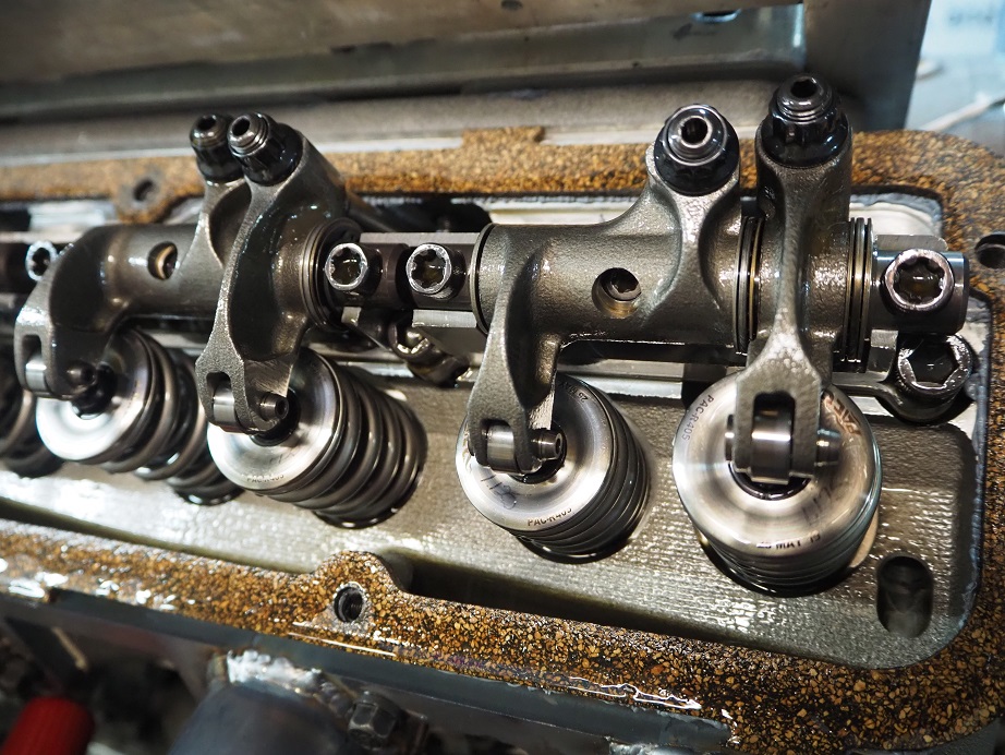
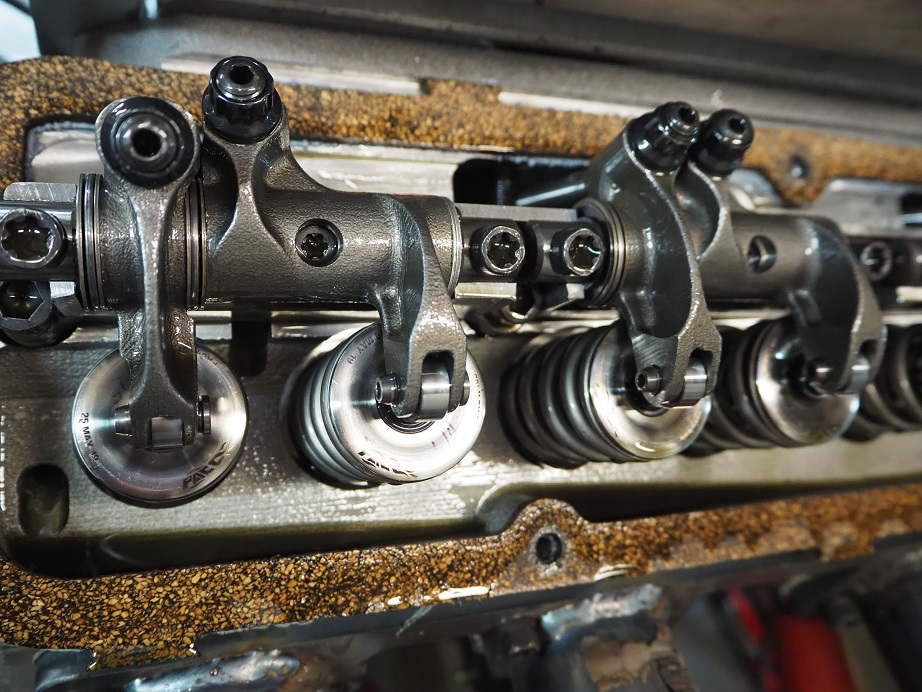
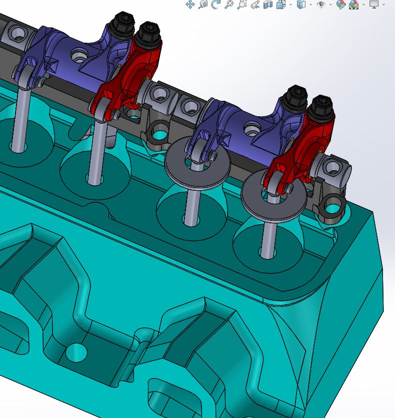
- Again today we observed no rocker arm issues.  I'm pretty confident with these rockers right now...
- The SE heads made almost as much power as the RE (Raised Exhaust) heads:

       RE heads, 8V intake:  860 HP, 734 lb-ft
       SE heads, 8V intake:  854 HP, 725 lb-ft

       RE heads, 4V intake:  857 HP, 719 lb-ft
       SE heads, 4V intake:  842 HP, 719 lb-ft

- The engine still peaks in power around 6500 RPM.  A new cam is coming, hopefully to change that...


I had started getting the SE heads ready to install earlier this week, but various issues took me away from the project, and I wasn't ready to test until today.  After getting all the valves and springs swapped from the RE heads to the SE heads, I finally got the SE heads bolted on Wednesday afternoon.  One thing that made this easier was the ability to re-use the SCE MLS head gaskets.  When I had pulled the RE heads off the engine and cleaned up those gaskets, they still looked brand new.  I contacted SCE and asked if there was any reason to spray them with Copper Coat or something like that to ensure sealing, but Ryan at SCE told me to just go ahead and install them again if they looked good.  So I did, and again they sealed perfectly.  My experience with Cometic MLS gaskets has not been as good; usually the black coating on the Cometics comes off around the cylinder bore after the first installation, and so I end up spraying those with Copper Coat in order to re-use them.  Doesn't appear to be necessary with SCE's gaskets.

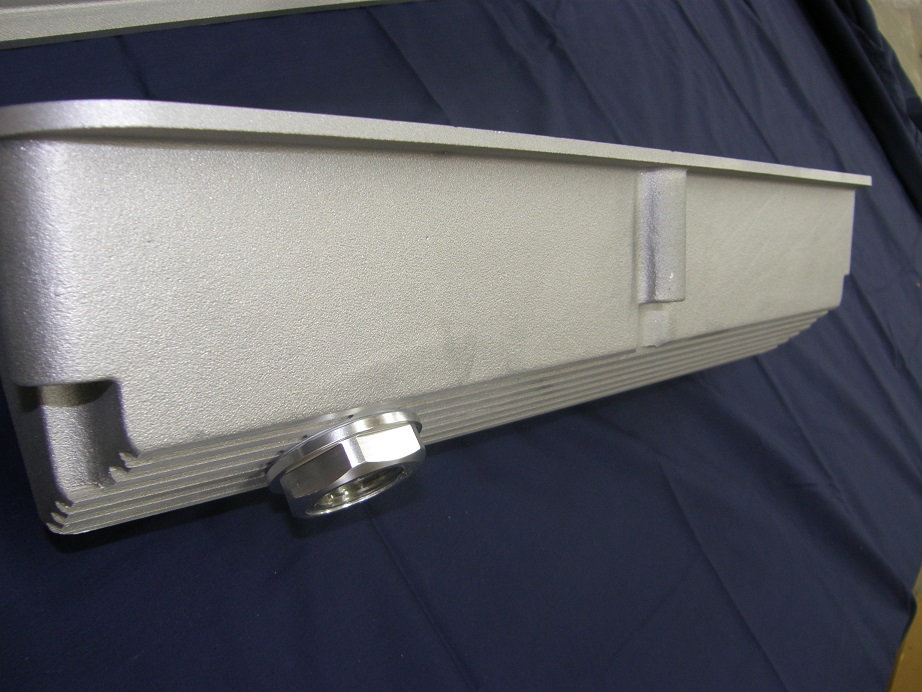
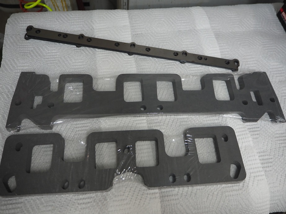
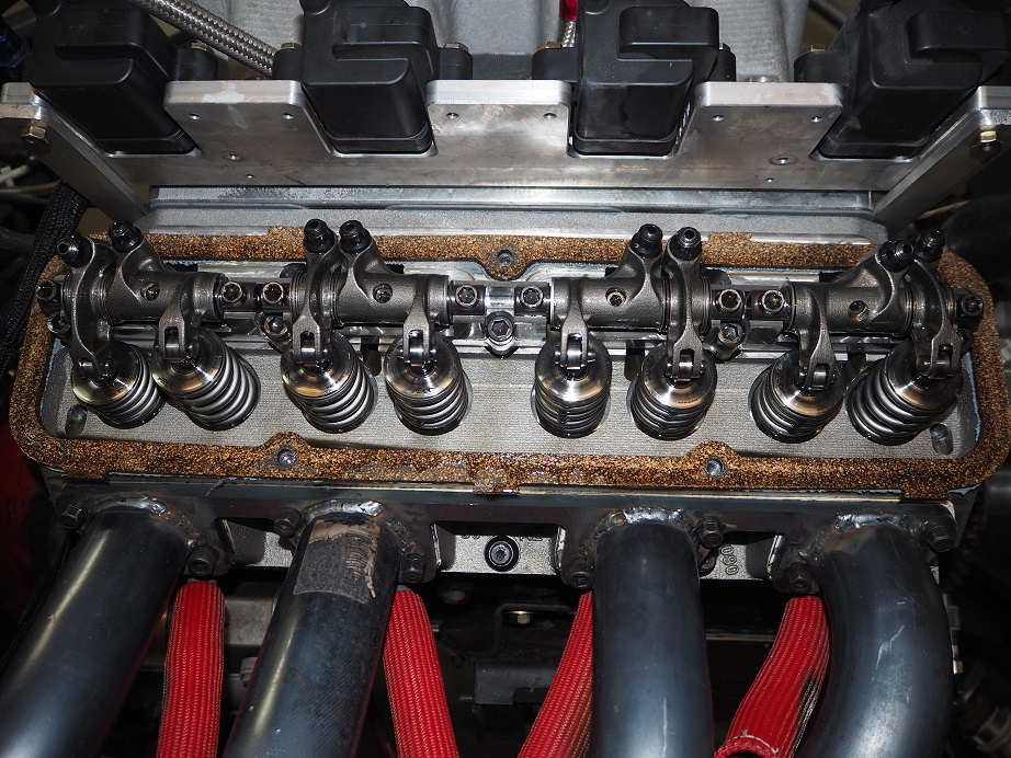
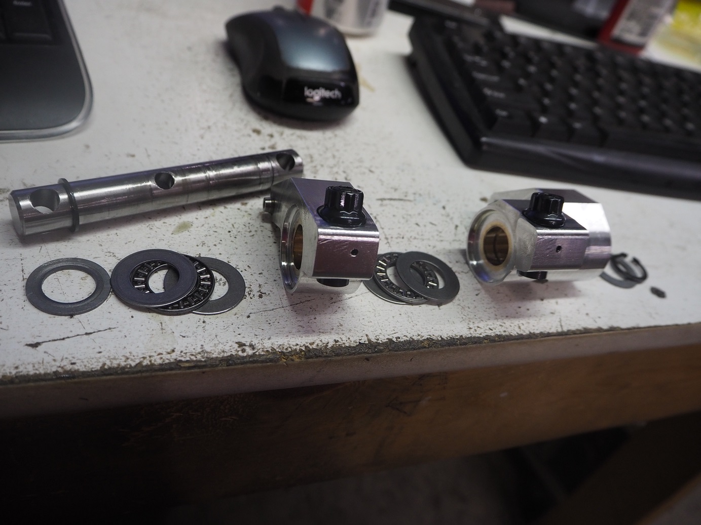
I'd also had SCE make up some intake gaskets for me, which made the cylinder head and intake change a lot easier.  I hate cutting out gaskets  ;D  A picture of the head to intake adapter gaskets, and intake adapter to intake manifold gaskets, along with the shims to adjust the height of the rocker arm system, is shown below:


It actually took me until this morning to get the rest of the engine put together and ready to run.  Once again today I had help from my pal Royce on the dyno, and also from my pal Kevin (thatdarncat on this forum), helping me work through the issues on the dyno.  The day started a little slowly because one of the batteries used to power the dyno basically just gave up, so we had to replace that battery and reconfigure some of the wiring to match the new battery post configuration.  After that, it was pretty smooth sailing.  As mentioned the engine was equipped with my SE cylinder heads this time, and the headers were Hooker adjustable race headers for a 67-70 Mustang chassis, with 2-1/8" primaries, and a 3-1/2" outlet collector.  They were not equipped with any of the primary extension pipes; they were set at the shortest possible length.

Other than those two changes, the engine was identical to the configuration shown in the previous thread.  It is noteworthy that the SE cylinder heads have an exhaust port that flows about 25 cfm less at peak than the RE cylinder heads, so I figured it would be down significantly on power.  However, the SE heads look on casual inspection to have a better spark plug location.  The chambers between the two head types are actually identical, but the angle of the spark plug, and it's position as it enters the chamber, are different between the two heads.  As a result, the first few pulls on the dyno were done to determine the best timing for the SE cylinder heads.

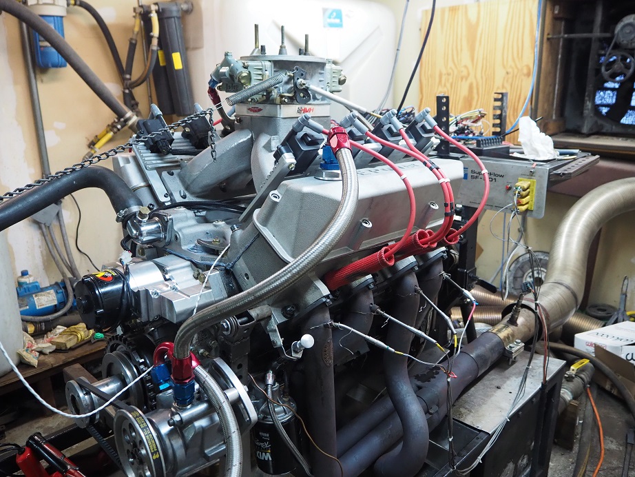
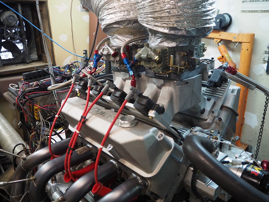
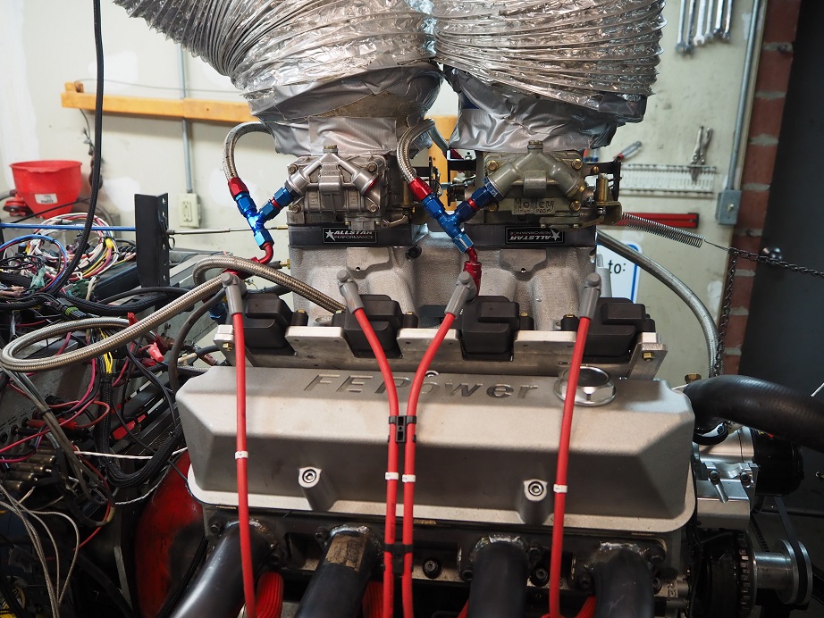
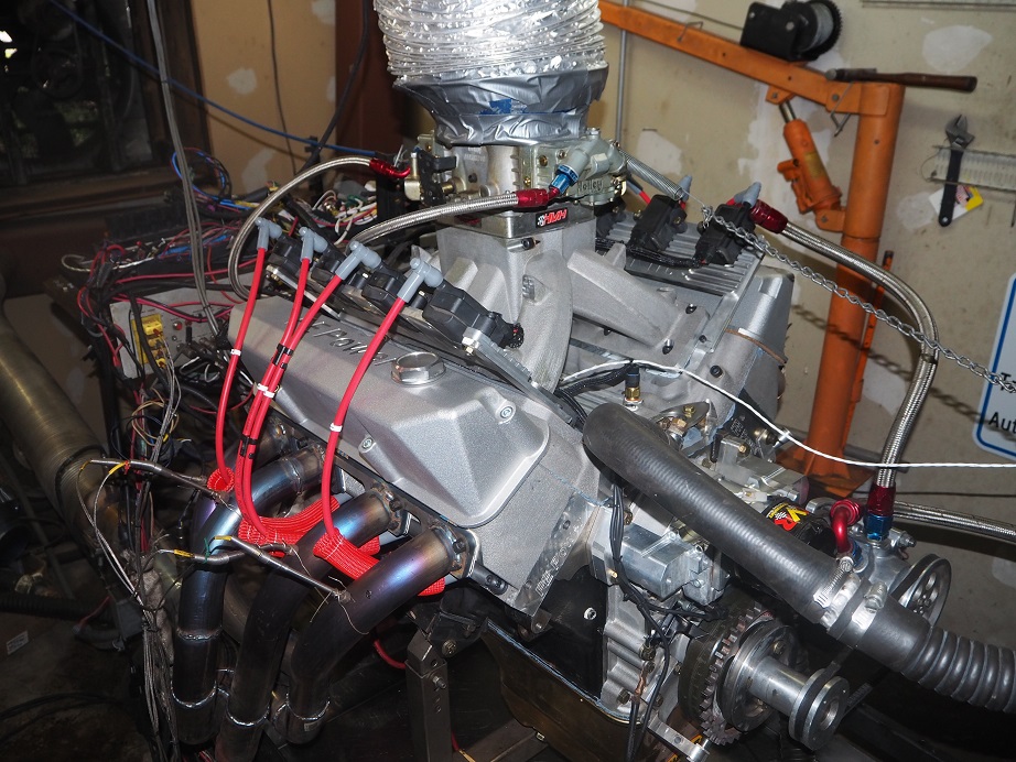
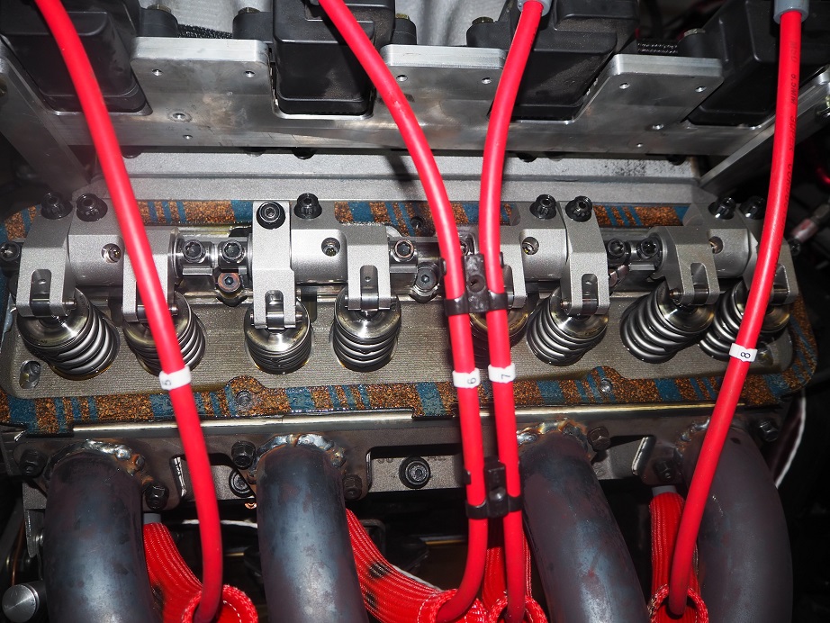
Here's a picture, taken by Kevin, of Royce and I working on the engine with the 8V intake installed:


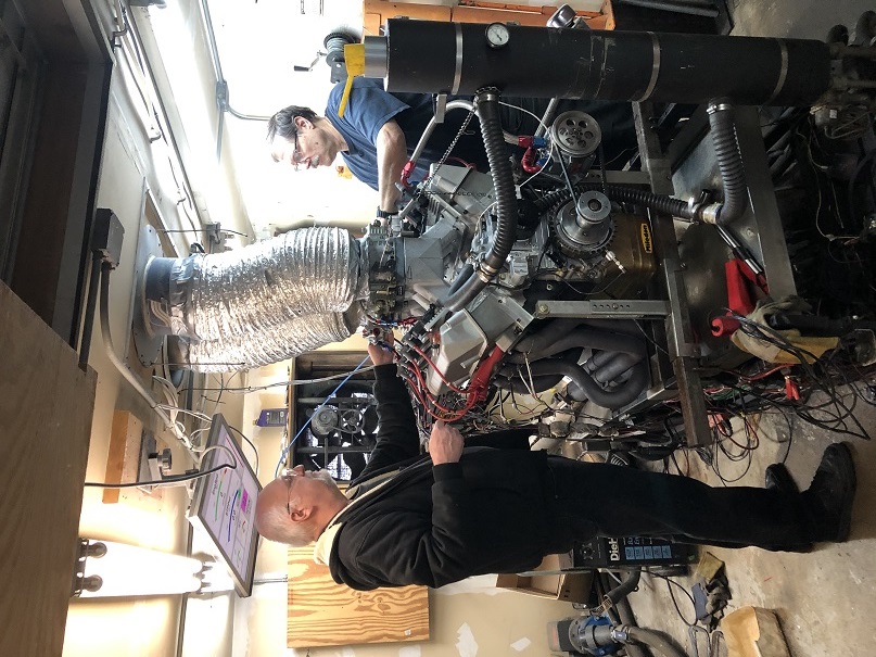
The 8V induction system was the one we started off with because it had already been set up during the last test session.  We just basically bolted it on, with the same jetting, and started the engine.  We ran it up to temp, then pulled the valve covers to lash the valves, and then began the pulls.  Our first few pulls were 3000-5000 RPM, in order to dial in the timing.  We started at 28, then went to 30, and then 32.  At 32 degrees total, the engine was actually down on power compared to the 30 degree test, so for the remaining tests we dialed the timing back to 30 degrees.  On the RE heads, best results were obtained at 32 degrees, so it was cool to see an actual effect from the different spark plug locations between the two heads, and it seems it would definitely be a good thing to move the plug location in the RE heads. 

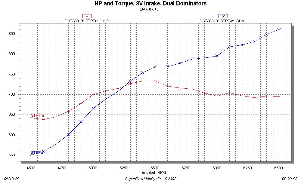
After getting the timing dialed in we quickly ran up the RPM range, finally arriving at the 5000-7000 RPM pull.  Again, as in the previous tests, the engine made power up to 6500 or so, but then quit climbing higher.  I had figured that we would be down 20-25 HP due to the less efficient exhaust on the SE heads, but was surprised to find that they were nearly as good as the RE heads.  The data below shows a comparison of the SE and RE heads with the 8V  intake manifold and carb setup.  Note that the best pull we got with the RE heads was up to 6500 RPM, so that is the one that is shown:


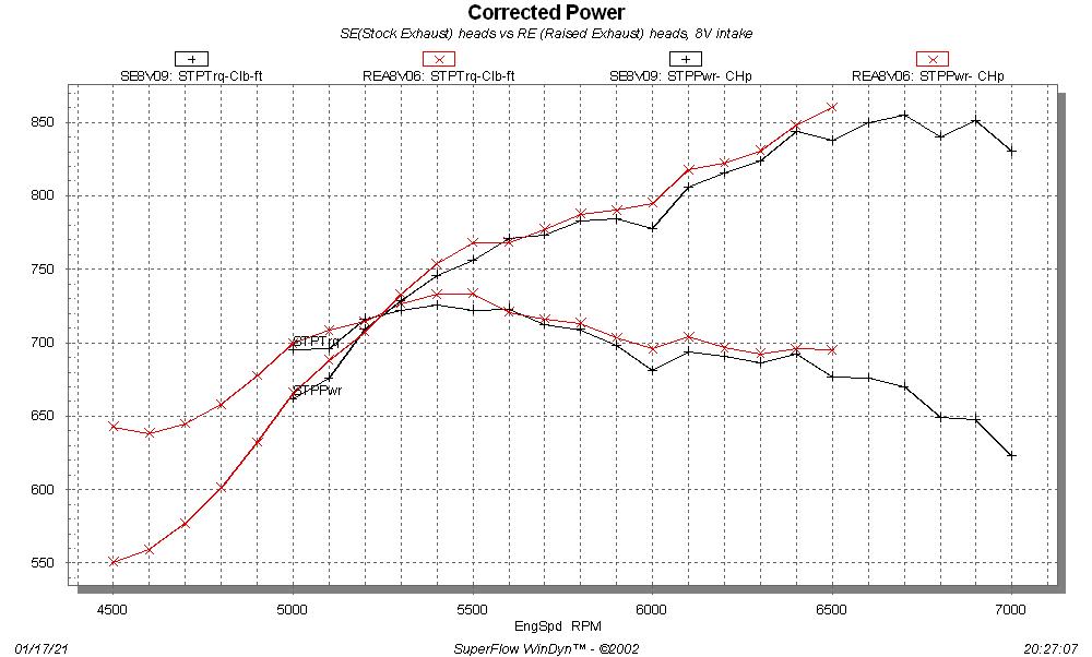
This is really not that big of a difference, and I think it shows that the intake port is far more important than the exhaust port.

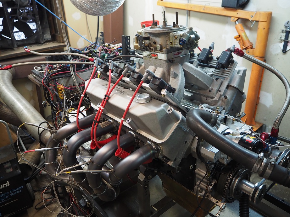
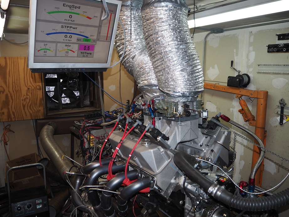
Next we pulled the 8V intake off and installed the "Rasputin" (Tall and Terrible) 4V intake.  Royce gets credit for naming that one.  Here's a picture of the engine at this point:


We re-jetted the 1150 Dominator carb to match the jets that we ran with the RE heads, and started the testing.  Everything was fine until we got to the 4500-6500 RPM pull; suddenly before started the pull we heard a loud knocking from the engine.  Ruh-Roh...  We looked for some issue that would cause that, but it sounded just like a connecting rod to me; it appeared to be coming right from the side of the engine block.  Finally though, after changing and restarting the engine briefly a couple times, and listening and watching, I saw that one of the header pipes had come loose from the head, and it was knocking against the head as the engine vibrated while running.  What a relief LOL!

After tightening the header bolts we started the engine and ran the 4500-6500 pull, but it had a big flat spot in the middle of the pull.  We were scratching our head about this, but then it dawned on me to look in the gas tank.  Barely anything left there, we had basically run out of gas.  Duh... :-[

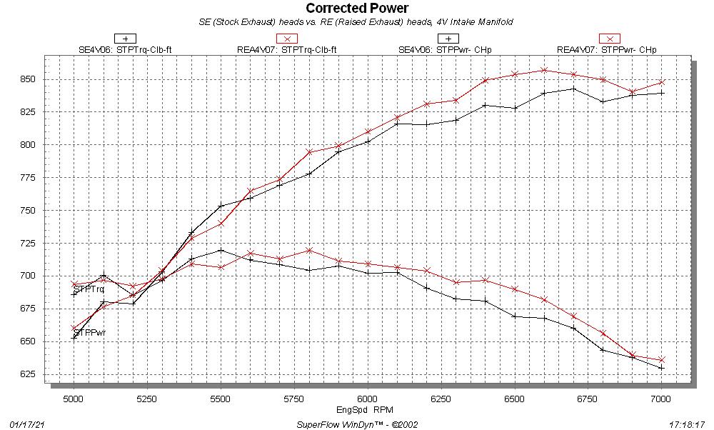
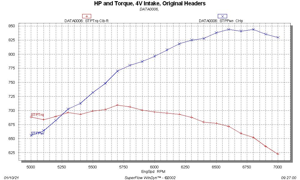
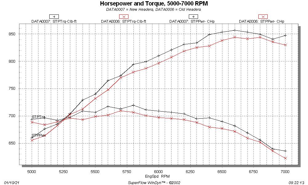
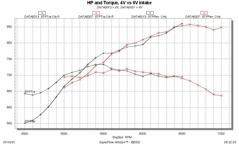
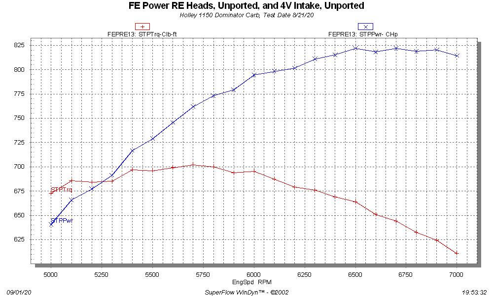
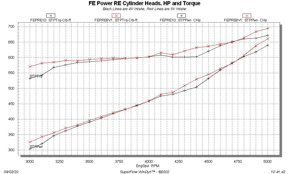
I added gas and then the next two pulls, 4500-6500 and 5000-7000 RPM, were uneventful.  It was interesting that with the 4V intake the SE heads made the identical torque number to the RE heads, but were down more on power at the top end than the 8V intake was.  Here's a graph of the SE vs RE heads, with the 4V intake:


After that pull we called it a day.  I have a new cam coming, hopefully sometime this week, with less intake duration and less lift, but a bigger split for duration between intake and exhaust, and less overlap than this cam.  I'll install that as soon as I get it and test the SE heads again, then change valve springs to something less radical and test again.  I'm really looking forward to dialing in this combination.

In addition, I need to get the crossram intake set up and tested on here with EFI, that will also be coming in the next weeks.

Finally, a few notes from the testing today.  Ross had asked about lift at the retainer with this cam, and I was surprised to see it was only 0.786".  Without any valvetrain flex it should be 0.850", but with these big springs I'm obviously losing a lot.  I'm guessing that backing down on the spring pressure will help HP in more ways than one.

Also, again today the 8V intake showed zero manifold vacuum all through the pull.  At idle however, it was showing significant vacuum, around 9" or so, so I know for a fact that it was working properly.  The 4V intake only showed about 1.1 inches of vacuum with these heads, at 7000 RPM, compared to 1.6 inches at the same engine speed with the RE heads.  So, obviously those heads are pulling harder on the intake than the SE heads.  Certainly an indication that the better exhaust port on the RE heads is having an effect.

Finally, with todays weather conditions the correction factor for the dyno was 4.0%.

I will post another update after the cam change - Jay

32
FE Technical Forum / FE Power Cylinder Heads on the Dyno, Round 2
« on: January 10, 2021, 01:01:22 PM »
Got some better results this time.  This will be a long post, so here's a quick summary:

- The rocker arm breakage problem appears to be solved, the 4140 steel rockers held up without any trouble.
- RE (Raised Exhaust) heads were on the engine, still in unported condition.
- The 4V intake and 1150 Dominator carb peaked at 857 HP and 719 lb-ft of torque.
- The 8V intake and dual Dominator carbs peaked at 860 HP and 734 lb-ft of torque.
- The engine still doesn't want to make additional power past about 6500 RPM; not sure why at this point...
- Will be testing the SE (Stock Exhaust) heads this week.

It has taken way too long to get to this point, but finally last week I started getting the engine back together to run more dyno tests.  I'd had it torn down to the short block because after the last dyno session I thought I had bent a valve, but that turned out not to be the case.  Instead, I discovered a coil bind problem on the #8 exhaust valve, where the inner spring wouldn't fit completely up on the retainer.  This led to a coil bind condition on #8 exhaust, which was why it was jamming the adjuster back into the aluminum rocker.  I ended up having all 16 retainers machined to fit the springs better, because they were all pretty tight.  After getting the new rocker arms finish machined, I reassembled the heads and got the engine back together.

After installing the heads and the first pair of rockers I measured for pushrods and ordered a set from Smith Brothers.  I had ordered them with .040" restrictors in the pushrods, but when they arrived they didn't have the restrictors installed.  I decided to run them anyway, so after assembling the engine I pre-oiled and watched for oil flow onto the retainers.  Sure enough, a couple of them got oil much faster than the others, and it seemed to take longer to get oil to all 16 rockers than it did the first time I ran this engine (with the aluminum rockers and different pushrods that DID have the restrictors).  So I'm thinking that the restrictors are probably a pretty good idea on this setup.

After pre-oiling I got the 510" engine the rest of the way back together.  Here's a picture of the engine on the dyno, with the 4V intake installed, and also some pictures of the rocker arm setup:


There were several changes to this engine on this go-around, most notably the rocker arms.  However, I had also sent the intake adapter and both intake manifolds down to Joe Craine for flow testing and some touch up work.  Joe found that the 4V intake was pretty good as is, but he did some cleanup in the plenum and on some of the runners to get them all matched up to flow the same.  On the 8V intake, Joe found that it needed quite a bit more work than the 4V; he did a lot of work smoothing the entrance of the runners into the plenum.  I am going to incorporate the changes Joe made into the designs of the intakes, so that the next castings come out with his modifications.  Joe has also offered to do some different porting on the 4V intake, so I'm going to send that one back down to him later this month, and then test again when I get it back.  I think it's really cool that I can get these parts modified to improve the power numbers, and then just build the modifications into the castings.  The power of 3D printing...

One other change to the intakes is going to be making them one piece rather than two piece; Joe thought that any decent porting guy could get into the runners of the intakes with no problem, so having the intake cast in two separate pieces is not really necessary.  That will reduce some CNC machining time here, which is a good thing.

The other major change I had decided to make was to the stepped headers for the RE heads.  My original set of headers used 2" pipes, 16" long, into 2-1/8" pipes 8" long, into 2-1/4" pipes 8" long, and then into a slip-on merge collector with a 2-3/4" choke and 4" outlet.  I had been thinking that the primaries might be too small, but I wanted to stick with the existing collector.  So, for a couple days before I started the testing, I built another set of primaries.  This set used 2-1/8" pipes 16" long, into 2-1/4" pipes, also 16" long. 

Thursday this week I finished assembling the engine and getting it ready to run.  My friend and Engine Masters competitor Royce B had come to help; it was good to have another set of qualified eyes on this process.  We started with the original, smaller headers, because I wanted to do a back to back comparison with the new headers when that time came.  Thursday night we left the shop with the engine basically ready to run.

Friday morning we got started with the dyno pulls.  It was a somewhat cold, high pressure day in Minnesota, and the air going into the engine was only about 58 degrees, so it led to a very small correction factor for the dyno, at 1.6%.  We made several  pulls from 3000 to 5000 RPM, to get the jetting adjusted properly in the carb.  After we got A/F numbers in the high 12s and low 13s, the engine was making about 10 more HP at 5000 RPM than it had been during the first dyno session in September.  So, we started increasing the RPM range in 500 RPM increments.  By the time we got to the 4500-6500 RPM pull, we were getting pretty good results.  I was very pleased with the torque number at about 710 lb-ft, and the HP number was up to 847.  I had been figuring about 850 HP with the 4V intake, so that was right on expectations.  Then, we ran the 5000 to 7000 RPM pull, but again, just like last time, the power curve just flattened out at 6500.  So 847 HP was all we got, even with more engine speed.  Here is a graph of the dyno results at this point:


We had still been running the old headers.  We let the engine cool for an hour before we changed to the new headers, to avoid the usual burns.  I was curious whether I had wasted a bunch of money on mandrel bent tubing, and a bunch of time building the new headers, or whether they would improve the situation.  Bottom line, the new headers were a win, to the tune of about 10 HP and 10 lb-ft of torque across the entire RPM range.  Here is a graph showing the results of the header swap:


So, best results for the 4V intake was 857HP and 719 lb-ft.  The HP number exceeded my target by a few HP, and I was especially pleased with the torque number; to get past 1.4 lb-ft per cubic inch is a great result. 

Royce and I spent the rest of the day on Friday removing the 4V intake and setting up the 8V intake for testing.  I had originally tested this intake with a pair of 850 center squirters, but Royce brought up his 1050 Dominator, so we thought why not just go ahead with the two Dominator carbs instead.  How those were fit onto the intake is rather interesting.  The 8V intake manifold is drilled with two 4150 carb bolt patterns, one for putting the carbs in line, and one for putting the carbs sideways.  When the 8V intake was down at Joe's, he discovered that using that bolt pattern, a Dominator flange carb would fit if you just cocked the carb a little sideways on each pad.  So, using two of the holes for the inline 4150 pattern, and two of the holes for the sideways 4150 pattern, a Dominator carb will fit on the intake.

This actually turned out to be somewhat of a challenge, because of the brand new BENT carb studs that I received from Summit Racing.  Must have been Chinese junk, because out of three packs, there wasn't one stud that was completely straight, and some of them were bent really bad.  ARP next time, I guess.  Regardless, we eventually got both Dominator carbs put onto the intake with 1" open spacers underneath.  We had to put together some new fuel lines, because the ones from the 850 center squirters weren't long enough, and I had to make up a new linkage setup, but finally at the end of the day on Friday, we had the 8V intake installed on the engine and were ready to run.  Here are some pictures of the engine with the 8V intake and dual Dominators installed:


Saturday morning we got started with the tuning by running several pulls from 3000-5000 RPM.  At first we were way rich, and we ended up leaning both carbs down.  However, my 1150 Dominator carb has power valves, and Royce's 1050 Quick Fuel carb doesn't, so we kept his jetted several steps richer than mine before we finally got the A/F numbers that we wanted.  We saw that at 5000 RPM, the 8V setup was up significantly from the 4V setup.  We also noticed that the engine started more easily with the 8V setup.

By the time we got to a 4500-6500 RPM pull, things were looking very promising.  Peak torque was up significantly, to over 730 lb-ft, and the HP numbers were looking good.  It is always dangerous to rely on the first number, or the last number, of any dyno pull data, but the last number for that pull looked like we were on the way to 900 HP.  Here's a graph of those results:


But on the next pull from 5000 to 7000 RPM, to our surprise and dismay, the curve flattened out again past 6500.  860 HP and 734 lb-ft were the peaks. 

We speculated endlessly on the cause of this behavior.  If I didn't have all the dyno data I'd say it was valvetrain, but on the dyno you can look at the airflow into the engine, and for both the 4V and 8V intakes, air flow continues to increase linearly past 6500 RPM, all the way to 7000 RPM.  With a valvetrain issue you will usually see the airflow go choppy, but that was not the case.  A/F is also pretty steady from 6500 to 7000 RPM.  So it doesn't seem like we were entering a valve float condition (which would be hard to believe with the valve springs I'm running anyway).  Our best guess is that the engine just doesn't like this cam, but it is certain hard to say for sure.

In any case, here is a graph of the 4V intake results vs the 8V.  Notice the big fat torque advantage that the 8V intake has from 5000 to 5600 RPM.


Royce and I had a couple of other guys from the forum join us on Saturday afternoon, and I took this opportunity to check the dyno's calibration while everyone was there watching.  After 15 years of dyno experience and over 100 different engines dynoed (including over 30 of my own), I tend to be a little bit suspicious of the some of the dyno numbers that I've seen from other dynos, and I know for a fact that some of them read high.  I wanted to be sure that these numbers were legit, so we checked the weather data that the dyno uses against the NOAA barometric pressure and my stand alone weather station for temperature, against the dyno readings, and they were consistent.  Then I loaded up the torque link on the dyno with the weight bar provided by Superflow, and added enough weight to get to 880 lb-ft of torque in several steps.  We found that the dyno torque reading was accurate within 0.5% all along the way.

At this point, I'm in the process of tearing down the engine and setting it up to run the SE (Stock Exhaust) heads.  I have to transfer all the valves and the valve springs/retainers/locks from the RE heads to the SE heads before I can get the engine back assembled, so it will be later in the week before I'm running again.  I think I will also start looking at a different cam, just as a test if nothing else.  I think that the as-cast heads are capable of supporting 900 HP, but we haven't got there yet, so I'll be working on that too.  I will add the results from the SE heads to this thread when I have them, towards the end of the week.

33
FE Technical Forum / 69 Cobra (Torino) Factory Appearance?
« on: December 23, 2020, 09:52:35 AM »
My pal Steve the bodywork expert has been looking for a winter project this year, so I've struck a deal with him to do the bodywork on my 69 Cobra.  He just took it to his shop on Monday, and it will probably be ready for paint in the spring.  So now I'm looking at the exterior appearance of the car, and whatever options there may have been for that.  The car was originally Ford's Candy Apple Red, and it will be repainted in that color.  However, the car also has black on the center of the hood, the hood scoop is black, and the taillight panel is black.  After carefully scraping some paint, it appears that the taillight panel was originally red.  But I can't find any evidence of prior red paint on the hood, where it was painted black.  Also, the underside of the scoop appears to have been red, but the top was painted black, and again there is no evidence of red paint under the black on the scoop.  Pictures of the car as I received it are on the second page of this thread:

http://fepower.net/simplemachinesforum/index.php?topic=2795.0


Looking online I see lots of different black and body color combinations, and also some that have no black at all.  I also see a lot of cars with the tape stripe on them; I like that stripe, and am inclined to put it on this car.  But if they never came with that then I'm not sure I'd want to do it.  So, my questions are as follows:

- Was the tape stripe an option for the Cobras?

- Did the factory ever put black paint on any portion of the cars?  If so, where?  I see black on the hood, hood scoop, taillight panel, and also the grille of some of the cars pictured online...

- I also see a lot of the cars with the "Cobra Jet" script on the hood scoop, in addition to the 428.  Was that ever done by the factory, or are those instances owner-installed?


Bear in mind that my car is an early car, built right at the end of 1968.  It is a factory 428SCJ car, with the 4 speed and 3.91 Traction Lok, but it was built before Ford started calling them Drag Pack cars.  Any info on this is appreciated.  Here are a couple of pictures of my car, as I received it five years ago:


35
Private Classifieds / Wanted - Edelbrock 2863 intake
« on: December 21, 2020, 05:13:07 PM »
I have a customer looking for ones of these intake manifolds; they were originally for a 351C.  They work really well with my 13006 intake adapter.  If you have one please let me know, and I will forward you my customer's contact info.  Thanks, Jay

36
FE Technical Forum / FE Power Cylinder Head Rocker Update
« on: September 21, 2020, 08:15:09 PM »
So after the intake rocker arm failures on the dyno when running my cylinder heads for the first time, I had pretty much concluded that going to a steel rocker arm would be the best solution.  After speaking with some contacts in the industry, an investment cast steel rocker arm looked pretty attractive.  I considered just machining the rockers out of billet steel, but that is a difficult and time consuming process, and would have added a lot to the cost of the cylinder head system.  Starting with an investment casting had a lot of benefits in terms of reduced machining time and tool wear, so overall cost was going to be lower despite an initial investment in tooling. 

As it happens there is a well regarded investment casting company only about 30 minutes away from me, so that also offered a big advantage.  I contacted them and arranged to discuss the project, and get a tour.  The process they showed me is really cool; for whatever reason, I find foundry manufacturing very interesting.  The investment casting process starts with 3D printing some kind of low temperature plastic into the shape of the finished part.  Then this plastic is dipped in wax to fill in all the pores, and takes several trips through a ceramic encapsulation process, to build up a ceramic shell around the part.  For most parts, the process then attaches multiple individual parts to a "tree", which basically forms the path that the molten metal flows into during the pouring process.  When it's all ready, the tree is heated up to a temperature high enough to melt the wax and 3D printed plastic, allowing it to be poured out of the ceramic mold.  Then, the metal is poured into the empty mold, and the parts are cut off the tree after the metal cools.  I watched them pouring some stainless steel during the tour, and the ceramic tree glows bright red when the metal goes in, but maintains it's shape.  It was much, much different than the sand casting I'm used to seeing.

Anyway, shortly after the dyno session I got busy redesigning the rocker arms in 4140 steel, which is an alloy used in many other steel rockers, and is regularly poured by the investment casting company.  In the dyno thread there were some examples of steel rocker arms posted, and I studied those pretty carefully and tried to incorporate some of the design features into the new rockers.  One decision was whether or not to cant the adjuster on the intake rocker to line up with the intake pushrod angle, and after some consideration that seemed like the best approach.  There will be an additional machining fixture required, and two more steps to the machining process in order to do this, but it seemed like it would be worth it from a valvetrain stability standpoint.  After a week or so of design work, I had first pass designs for the intake and exhaust rocker completed, similar to the ones shown in the CAD picture below:


My pal Bill Conley took the first iteration of the designs and ran them through his FEA  program, to see where they were stressed with 1000 pounds of valve spring pressure.  Bill's help has been crucial to this effort, and right away he thought the designs had promise, but could use a little tweaking.  I would not have known where to add material or how to analyze these designs without Bill's help.  We went back and forth on this a few times, where I made modifications to the file and Bill analyzed them, and we finally had an intake and exhaust rocker design that looked solid.  The pictures below are from Bill's FEA software program, showing areas of stress in the rocker arms with the aforementioned valvespring pressure.  Red areas are to be avoided if possible, but Bill thought that based on his experience the red areas on these plots would not be a cause for concern.

Exhaust Rocker:


Intake Rocker:


The areas in red were not where I was seeing failures on the aluminum rockers on the dyno, so it seemed like I could proceed with these designs.  One concern about the steel rockers was weight of course, but these designs turned out to be nearly as good as the aluminum rockers.  Moment of inertia is a measurement of how a body resists acceleration forces, and is the key metric for achieving a lightweight valve train.  According to the FEA analysis, the exhaust rocker has a moment of inertia only 8% higher than the aluminum version, which is not much of a difference.  The intake rocker is even better, at only 1.5% higher; basically it is so close as to be the basically the same as the aluminum version. 

With the data and analysis complete, I ordered a set of prototype rockers from the investment casting company.  Unfortunately they are 4-6 weeks out, so it won't be until late October before I get them.  Then they have to be machined and assembled before I can run the engine again, so now it is looking like early November before I have the next dyno results.

In the meantime Bill and I got to talking about fatigue life of the steel rockers; I was curious about what could be expected there, so Bill ran yet another analysis to figure this out.  In the charts below the different colors relate to a baseline of 50 million cycles.  Orange is exactly 50 million cycles before the onset of fatigue issues, yellow and green are more cycles, and red is less.  Again based on Bill's experience the red areas are not a major concern.

Exhaust Rocker:


Intake Rocker:


This analysis again assumed a 1000 pound valve spring when the valve is fully open.  The 50 million cycle number should go way up with lower valve springs pressures, like 800 or 600.  So based on this I'm feeling pretty confident about this design.  The dyno testing will tell for sure, at least in the short term.

The only downside to all this is the further delay while the rockers are manufactured before I can resume testing.  But I spent my professional career in product development, and it always seems to go like this, especially on complex projects.  Hopefully next time around the engine will hold together like it's supposed to and we'll get some really good data.

37
FE Technical Forum / Update on the FE Power Cylinder Head Testing
« on: September 02, 2020, 12:57:15 PM »
As time has permitted over the last couple of weeks I've been getting some dyno time in on my cylinder head package.  I have some dyno results, which at this point are not quite as good as I was hoping for, but close.  I think I've identified the horsepower issues and am working to get those fixed.  I have also found a valvetrain issue, which is in the process of being corrected, but the valvetrain issue caused a bent valve, so I need to get that fixed before I can continue testing.  The good news is that the heads appear to be solid, with no issues that I can see at this point.  The intake manifolds need some development work, which I'm hoping won't take too long; I'd like to be back testing on the dyno in 3-4 weeks.

I apologize in advance for this very long post, but I wanted to get this documented while it was still fresh in my mind.  Lots of things have been happening on this project over the last couple weeks.

Here are some details on the dyno mule, which is a 511" engine:
 - Pond block, 4.310" bore
 - RPM forged crank, 4.375" stroke
 - Crower billet rods, 6.700"
 - CP Pistons, with .039" steel top ring, .039" Napier second ring, 11 lb 3mm oil ring, 13.0:1 static compression.
 - Milodon 8 quart pan and pickup
 - Moroso windage tray
 - Precision Oil Pumps high volume pump
 - Bullet solid roller cam, 285/292 @ .050", 0.880" gross valve lift
 - FE Power RE (Raised Exhaust) heads, 2.300" intakes, 1.675" exhausts, unported
 - PAC 1356 springs set up with 340 pounds on the seat and about 1000 pounds over the nose
 - FE Power intake adapter for the cylinder heads, port matched to the intake and the heads
 - FE Power 4V or 8V intake, unported
 - FE Power rocker arm system
 - Smith Brothers 7/16" pushrods, with 0.040" restrictors built in
 - FE Power valve covers, first the clear top version, then the standard pentroof version after initial warm up
 - GZ Motorsports vacuum pump
 - DIY Autotune EFI system, used for ignition only at this point.  Crank trigger, cam sensor, and individual coil packs.


Here's what the engine looked like during most of the dyno testing:


So far I have only tested the RE version of the cylinder heads.  Most of the testing has been done with the 4V intake manifold, but I did make a few pulls with the 8V intake also.  I was hoping for 850 HP out of the 4V intake and Dominator carb, and 900 HP out of the 8V intake and two 850 carbs.  Testing has been interrupted numerous times with valve train problems, which I will try to describe in detail below.  For now, this was the only pull to 7000 RPM with the 4V intake and Dominator carb:


I guess 820 HP isn't too bad as a starting point.  One notable thing about this dyno pull was that the manifold vacuum at 7000 RPM was 2 inches; that's a whole lot, and indicated that the carb could be too small.  But that turned out not to be the case, from some later test results.

Backing up, I got the engine on the dyno in the middle of August, built the headers, and double and triple checked everything before starting to test.  Starting it up was a real thrill; every cast aluminum part, and almost all the billet parts on this engine, started life on my computer screen.  It was great to see all that work suddenly running an engine.  I started it with the clear top valve covers so that I could watch the oil flow in the valvetrain area, and it looked just fine.  Warm up was uneventful, and after running for about 15 minutes I shut the engine down to lash the valves, then installed the regular valve covers, which seal better when using the vacuum pump.

The next day Royce B came by to help with the testing.  Kevin R was also there, and a few others.  We started with a cruise test just to see how the air/fuel looked under load, and it seemed at the lower engine speeds it was OK, so we ran a dyno pull from 3000 to 4500, changed jets, ran from 3000 to 5000, jetted up again, and with the A/F looking good we started running higher.  But, at the start of one of the pulls, while the engine was still warming up, we heard a noise that sounded like a bolt had dropped into the sheet metal pan on the dyno, under the engine.  We went out and looked, but didn't see anything.  On the next pull, we were down 75 horsepower from where we had been.  I pulled the valve covers and discovered this broken intake rocker:


Just for reference, here are a couple of pictures of the intact valvetrain:


With the big valvesprings there are a lot of torsional stresses on that intake rocker.  Bill Conley had helped me with an FEA analysis of the design, and it appeared that the design would hold, but it seemed that we were looking at a fatigue failure, rather than a strength issue.  Looking at the broken rocker, you can see it is pretty thin over by the adjuster.  Larry Tores at T&D Machine had mentioned to me at the PRI show last year that most fatigue failures start right in this area, so I figured that's what was happening. 

The reason that the rocker is thin there is that it is counterbored in that area for a thrust bearing.  During the FEA analysis it became clear that the side loads on the intake rocker were going to be pretty large, due to the angled pushrod. So, I designed the intake rocker with a thrust bearing that bears against the exhaust rocker, and of course since the force is transmitted through the exhaust rocker, it needs a thrust bearing on the other side too.  Here's a picture of a rocker pair assembly taken apart, showing the thrust bearings and the steel washers they ride against:


Well, it was possible that this was just a bad rocker, and I had a few spares, so we replaced that one and continued running.  We had no further issues for the remaining dyno tests, and made the one pull from 5000 to 7000 RPM.  I was very happy that the valvetrain seemed to hold together with no problem up to that engine speed.  But it was, and still is, a mystery to me why the engine peaked in power at about 6500 RPM.  I've got to believe that the cam wants to go higher than that. 

Next, we pulled off the 4V intake and 1150 Dominator, and installed the 8V intake and two 850 center squirter carbs.  I had really high hopes for this one, but unfortunately our testing was cut short by more rocker arm problems.  The first pull with the 8V intake, and really the only good pull, was 3000 to 5000 RPM.  The motor was pig rich, even showing some A/F numbers in the 9s, which you never see.  Nevertheless, it still showed a lot of promise.  The graph below shows the best 3000-5000 RPM pull with the 4V intake, and the first pull with the 8V intake:


At 5000 RPM, despite being very rich, the 8V intake looks to be pulling away from the 4V intake, up by 20 HP to 660 HP at that point.  But that was as good as it got.  We jetted down, and for some unknown reason, A/F started looking better but power was down substantially.  We tried another pull, and then the motor just didn't sound right.  Pulled the valve covers, and found two more broken intake rockers.  Crap  >:(  Done for the day.

The conclusions from the first round of testing were twofold:  The intake rocker needed to be redesigned to add material around the adjuster, and the 4V intake needed to be tested with a bigger carb, to try to reduce vacuum at wide open throttle.  On the intake rocker, I didn't have room to move the adjuster towards the thicker side, because then the pushrod would hit the intake adapter.  But the exhaust rocker was thicker on both sides of the adjuster than the intake rocker was on it's thin side, and since the pushrod comes straight up for the exhaust rocker, it wouldn't be subject to the kind of torsional stresses that the intake rocker was.  So, I moved the counterbore that had been in the intake rocker over to the exhaust rocker, to leave the intake rocker as thick as possible around the adjuster. 

For the next few days I revised my CNC programming for the rocker arms and machined a new set of intake rockers, and modified the existing set of exhaust rockers.  Along the way, Royce talked to Jon Kaase about the issues we were seeing (Royce knows Jon from his Engine Masters engines, and I've met Jon at the PRI show).  Jon steered Royce to a guy who makes Kaase's top end rockers, and there was an online article about his parts.  One of the things I found interesting in his article was that he shot peens his aluminum rocker arms.  I thought this might be a good thing for me to do also, because machining aluminum creates tensile stresses on the outside of the material, and can lead to fatigue problems.  Shot peening changes those to compressive stresses, which are more resistant to fatigue.  I found a local company who could shot peen my rockers, so I dropped them off for the work.  They were able to get it done in a couple days, and I got them back last Friday.  Here's a couple pictures of the shot peened rockers:


In the meantime, Royce had found a guy with one of those billet body 1400 cfm Dominator carbs, who was willing to lend it to us for testing.  He brought it up last Friday, but it took most of the afternoon to re-assemble the valvetrain.  Installing it, we encountered a strange problem with the rockers; even with the adjusters backed all the way off, there was no lash.  I found out later that shot peening can deform aluminum, and the shot peening operation had actually changed the dimensions of the rockers, leading to the problem.  I shimmed up the stands to get some lash, but then when the rockers started getting cycled with the engine running, the lash started backing out; apparently the rockers were relaxing into the original machined shape.  I won't go into all the details, but this led to some weird noises from the valvetrain, that we finally figured out were broken adjusters; continually adjusting the lash had left them sticking too far out of the rocker arms. 

Finally by Saturday afternoon we had this all ironed out, engine was running fine, no more lash issues, etc., and were ready to make a pull with the 4V intake and the big Dominator carb.  But I think we only made one pull, when Royce noticed some smoke coming out of the vacuum pump catch can when the engine was running.  We pulled the valve covers again, and on the left side I noticed that we had water in the oil.  Ugh  :(

So, one of the nightmare scenarios with these heads was that they wouldn't hold up to punishment under running conditions, despite the thick walls I had put into the casting design.  However, the problem turned out to be the intake gasket, which was leaking water at the rear water opening of the right head.  Sunday I pressurized the cooling system to find the leak, and then pulled the intake adapter off.  When I looked at it in detail it became plain that I had machined the intake adapter incorrectly, and not left enough material to completely cover the gasket over the hole in the rear of the head.  If I had installed the intake adapter without a gasket, I'd have seen about a .040" slot of the rear water opening in the head exposed.  The gasket held there for a while, but finally gave up on Saturday afternoon.  Another simple issue, that will be easy to fix with a correction to the machining program, but it stopped us in our tracks on Saturday.

By the end of the day Monday I had made up some thin brass plates to block off the rear water jacket holes in the heads, and re-installed the intake adapter and valvetrain.  Tuesday I ran the engine again, with the 4V intake and the big carb, but encountered another problem with the #8 exhaust rocker.  During operation, it was jamming the adjuster back into the body of the rocker arm, opening the lash way up.  #8 had been one of the cylinders where one of the intake rockers had failed during a pull, and I'd been wondering if I'd done some damage in one of those cylinders. This morning I fabricated a tool to remove the valve springs with the heads on the engine, and did a leakdown check on #8, and sure enough the exhaust valve is bent.  I'm thinking the bent valve contacted the piston and jammed the adjuster up into the rocker arm.

I did get some good data up to 6000 RPM with the big carb, and much to my surprise, the engine was pulling the same amount of vacuum that the 1150 Dominator was at the same speeds.  I don't think there's any way that carb is too small, so now I'm suspecting the 4V intake manifold is a restriction, and probably limiting power production.  I've been talking to Joe Craine, and he has agreed to flow both the 4V and 8V intakes, on the intake adapter, and make some modifications to improve them.  Anyone who has been following this project probably remembers that my first go around with the RE heads showed exhaust flow that was not that great; I sent part of a head down to Joe and he modified the port to work better.  Then I took the modifications and incorporated them into the casting patterns, and the exhaust ports as cast picked up about 40 cfm.  I'm hoping that Joe can find some improvements in the intake manifolds, that I can also incorporate into revised castings.

I remain surprised by the relatively low RPM where this engine wants to peak in power.  I supposed it could be related to the intakes, but with a 285/292 @ .050 cam, I was figuring it would peak well over 7000 RPM.  I suppose it could be intake related, so we'll find out if that's the case when I dyno again with Joe's improvements.

Also, I've been thinking that I need to go to steel rocker arms on this setup.  Even though I haven't broken any more intake rockers since the design change, I've lost some confidence in them as a result, and would like a more bulletproof part.  I think while I am waiting for valves, and for Joe to flow the intakes, I will work on getting a revised design for a steel rocker arm finished and machined.  I'm also looking at an investment casting option for the steel rockers.

I will be back on the dyno with this engine as soon as possible, hopefully by the end of the month.  I'm not sure if I've fleshed out all the problems yet, but I've certainly identified the most obvious ones, so next time around the testing should go quite a bit smoother. 

38
One of my customers sent me these photos of the cars they are campaigning in Australia.  Really, really cool stuff  8)  
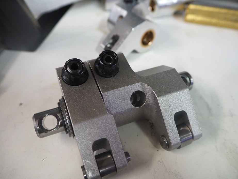
They also sent me a picture of their road racing 64 Galaxie, but it had a copyright mark so I couldn't post it...


39
Non-FE Discussion Forum / Unwelcome Visitor
« on: June 24, 2020, 09:14:32 PM »
One of our members sent me this photo of a critter that was dying to get in and see the old iron ;D  Literally...


40
Non-FE Discussion Forum / 429 Block Question
« on: June 22, 2020, 09:59:06 PM »
Tonight I saw a cast iron 429 block with screw-in core plugs.  Many years ago I had a 429 SCJ engine, but if I recall correctly it had normal press-in frost plugs.  Could this be a Boss 429 block?  Or an aftermarket block?  Thanks for any info - Jay

41
Vendor Classifieds / SOHC Gasket Sets
« on: June 09, 2020, 09:59:12 AM »
I'm getting ready to order another run of SOHC gasket sets.  These are sets that are specific to the SOHC, and include intake and exhaust gaskets, block end rail corks, all the front cover gaskets, but no head gaskets.  They are $190 + shipping for the set.  If you'd like a set, respond here, message me on the forum, email me at jayb@fepower.net, or give me a call at 952-428-9035.  I will be ordering them sometime in the next week or two, so time is limited.  Thanks, Jay


Update June 29, 2020:  Orders are closed, thanks to all who responded!

42
Somewhere I saw this picture, and can't remember where.  It showed a valve in a flow bench and you could see the flow of air around the valve.  Could be that there was some smoke or coloring added to the air, or it could have been a wet flow bench picture.  Seems to me I saw this in a book, maybe Power Secrets by Smokey Yunick.  Anybody remember seeing this picture?  I'd really like to have a copy of it.  None of the books I have show that photo...

43
Non-FE Discussion Forum / Paying Sales Tax on Online Purchases
« on: May 18, 2020, 08:27:03 AM »
I put some "blem" FE Power valve covers up for sale in the Vendor Classifieds yesterday, and had a guy contact me about the sales tax issue.  He wanted to know if he had to pay sales tax on purchases from FE Power.  Back when the Supreme Court decision made collecting sales tax on online purchases required, I had to do a bunch of research on that, so just for general information I thought I'd post what I found out about this.

The key point is that nearly all states in the US have reporting minimums for collecting sales tax, when the products are shipped from outside the state.  For example, California requires that if a business makes 100 sales into their state over the course of the calendar year, or sells at least $100,000 in products into the state, then it is required to report those sales and collect sales tax on them, then forward those taxes to the state.  If the sales are fewer than 100, or less than $100,000, then no reporting or collection of sales taxes is required.  Most other states have very similar requirements.  Illinois is 200/$100,000, Connecticut is 200/$250,000, South Dakota is 200/$100,000, Ohio has no minimum quantity but has $500,000 in minimum dollar value, etc. 

FE Power doesn't come close to these minimums for any state, so unless the purchase is going into Minnesota, I don't need to collect sales tax on any purchases.  It aggravates me to no end that I have to pay tax on purchases from Summit, Amazon, ebay, and any other large online retailers, but at least my customers who buy direct don't have to do that.  Just thought I'd put this up here for general information - Jay

44
I have three two one FE Power timing covers that are "cosmetically challenged"; the first one is pictured below.  They are functionally perfect, but the finish on the aluminum casting and the cover plate is not as good as I normally get with these, so I am selling them at a reduced price.  Normal price is $229, you can buy these for $150 each.  Shipping in the continental US is $16; if you are outside the continental US, please contact me for the shipping costs.  I can accept Paypal, credit cards or personal checks.  Please let me know if you have any questions - Jay


45
Updated 7/13/20:  Just finished all the machining on all the remaining valve covers.  I will not have any more for a while after these are gone.  I have updated the list below with the 8 7 pairs I have left.  Any questions, please let me know.  Thanks, Jay

Normally I take "blems" like these parts to the FE Reunion and sell them there, but since there hasn't been one this year (yet), I'm putting these up for sale on the site.  The pictures below are representative of the parts that I'm selling.  I'm offering a substantial discount on all these parts, in most cases $100 off the normal price, because I'm trying to clear out space for the coming cylinder head and intake manifold castings. 

The valve cover caps shown in most of the photos are for use with a screw-in breather; I like the ones by S&B, shown at this link on the Summit Racing web site:

https://www.summitracing.com/parts/sbf-26-1524

However, I can substitute plain caps, a cap machined for a PCV grommet (grommet included), or a cap machined for a #12 AN fitting if you would prefer.  All valve covers come with the bolts required to install them.

I still offer machining for master cylinder and power booster clearance at no extra charge for these valve covers.  I have yet to find a car that these will not fit, with the proper clearancing.  Also, I can still offer custom engraving on the plain (not finned) valve covers, such as block letters with your cubic inches, "FE", "FE Power", a Cobra Jet script, a Fairlane script, whatever.  Clearancing or custom engraving will add 3-4 weeks to delivery time.  Any custom engraving will add a charge of $60 to $125 (depending on what needs to be engraved), and the valve covers must be paid for in advance, but it's no problem for me to engrave most things on these covers.

Shipping for any of these valve covers to the continental US is $29; outside of the US, contact me and I can quote a shipping cost.  I can accept payment via Paypal, credit cards, or personal checks.  I will not accept returns on these covers.  Any questions, please let me know.

The valve covers shown below are my part number 17004, fitted with two caps for breathers.  I have one pair available; Sorry, sold out.  Normal price for these is $359 for the pair; scratch and dent sale $259 each pair:


The valve covers shown below are my part number 17006, fitted with two caps for breathers.  I have four three one Sorry, sold out.  Personally I prefer these covers, because it gets the breathers up at the front of the engine, rather than at the rear, where oil mist from the breather could be a bigger problem.  Normal price for these is $359 for the pair; scratch and dent sale $259 each pair:


The valve covers shown below are my part number 17006F, fitted with two caps for breathers.  I have one pair available, Sorry, this pair is sold.   normal price is $409 for the pair, scratch and dent sale $309 for the pair.  Also, I do have one plain pair, finned with no holes, still available.    Looks just like the pictures below, but no holes for breathers.  Normal price for those is $339 for the pair; scratch and dent sale $239 for the pair:
  Sorry, this pair is sold.


Pages: 1 2 [3] 4 5 ... 25