So after the last round of testing with these heads, we were suspicious that the cam was not really optimized for this engine. Lykins went so far as to offer to get me a cam at no charge, that he thought would be better suited for the engine. Not one to look a gift horse in the mouth, I said sure LOL!
Then, after picking out some cam lobes that he thought would work, Brent went to order the cam and found out, to his chagrin and mine, that blanks for FE cams to achieve over 0.800" lift were not available! Brent called a couple places and so did I, but the only thing that could be done would be to order a custom blank at around $900. Neither one of us wanted to spend that, so Brent settled on a cam with just under 0.800" lift. Here are the specs for the original cam that I tested with (the Old Cam), and the New Cam:
Old Cam: Bullet solid roller, 319/334 Advertised, 285/292@.050", 0.880" gross valve lift on both lobes, 112 LSA, .030" lash on exhaust, .028" lash on intake. I degreed this cam at 110 ICL.
New Cam: Comp solid roller, 305/317 Advertised, 276/288@.050", 0.782 gross valve lift on both lobes, 111 LSA, .018" lash on exhaust, .016" lash on intake. I degreed this cam at 111 ICL.
I sure hope that sometime soon the blanks for more lift on an FE cam become available, but for now all we can do is work with what we've got. It took me a few days to break free long enough to get the cam installed, but this past Friday I was ready to go. I had also acquired some new PAC valve springs that were more suited for either of the cams. Instead of about 1050 pounds over the nose, these were 800 pounds over the nose of the new cam, while still maintaining about 300 pounds on the seat, to get that heavy intake valve closed properly.
Royce and a couple of my friends were here on Friday to help with the testing. We started off with the existing valve springs still in place. On startup the first thing we noticed was how much smoother the idle was with the new cam. Makes sense due to less duration and overlap, but the difference was really noticeable. After warm-up and lash, we ran the first pull from 3000 to 5000 RPM. The new cam was so much smaller than the old cam that I wasn't sure what would happen, but as it turned out, the engine did not care about the cam. Here is chart showing the results from the new cam and the original results from the old cam:

These results were nearly identical, and given the more radical specs of the old cam, at this point I figured that the new cam would make less power up top. Wrong! Here is a chart comparing the two cams from 5000 to 7000 RPM:
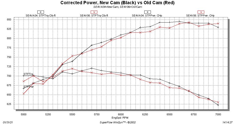
The new cam actually looks better at the top end than the old cam does. Go figure...
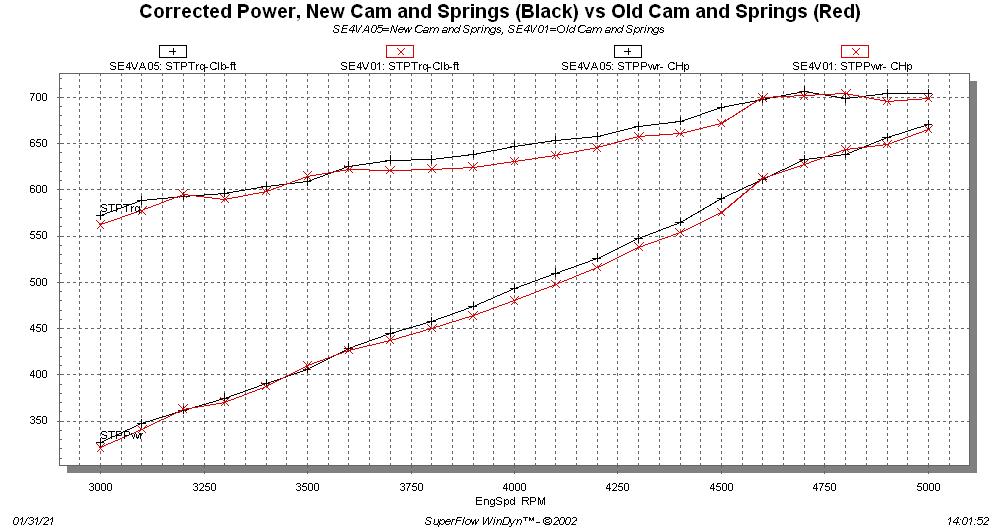
I'd been anxious to try a valve spring swap on the engine, because those big springs had served their purpose, by proving out the steel rocker arms. The swap was from PAC 1356 springs to PAC 1224 springs. I had made a tool to be able to swap the springs with the heads installed, and it took us a couple hours to get that done. After finishing, we warmed up the engine and ran the first pull from 3000-5000 RPM. The valvespring swap definitely picked up power, even at the lower engine speeds:
Finally, we worked our way up to the 5000-7000 RPM pull. Here the difference was even more pronounced:
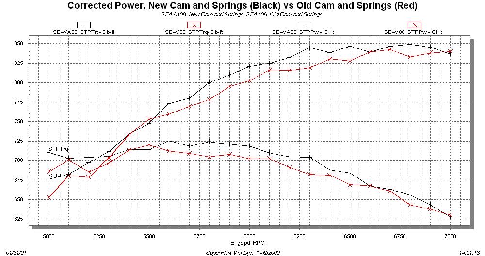
The torque and HP improvements using the SE heads and the new cam and springs are shown below:
SE heads, 4V intake, old cam and springs, peaks: 842 HP, 719 lb-ft
SE heads, 4V intake, new cam and springs, peaks: 849 HP, 724 lb-ft
SE Heads, 4V intake, old cam and springs, average 3000-5000 RPM: 491.9 HP, 639.6 lb-ft
SE Heads, 4V intake, new cam and springs, average 3000-5000 RPM: 497.7 HP, 647.2 lb-ft
SE Heads, 4V intake, old cam and springs, average 5000-7000 RPM: 781.3 HP, 685.8 lb-ft
SE Heads, 4V intake, new cam and springs, average 5000-7000 RPM: 792.2 HP, 695.6 lb-ft
Peak HP and torque numbers can always be a little misleading, so it's nice to see such a solid improvement in the average numbers as well.
After finishing up with the 4V intake on Friday, Royce and I swapped on the 8V intake. But after a couple of tests and a jet change, we were down some on power. Paranoia is always present during a dyno session, so out of an abundance of caution we called it a day.
Yesterday I spent some time going over the engine, checking the valve lash, changing the oil, etc. Everything looked just fine, and not a trace of an issue when I cut apart the oil filter. So this morning I reviewed the data that we had collected on the 8V setup on Friday, and realized that after the jet change our A/F numbers were way lean. So this afternoon when I ran the engine again I re-jetted to get it right. Today everything looked good, and we got the same kind of improvements with the cam and spring change as we did with the 4V intake. Details below:
SE heads, 8V intake, old cam and springs, peaks: 854 HP, 725 lb-ft
SE heads, 8V intake, new cam and springs, peaks: 861 HP, 736 lb-ft
SE Heads, 8V intake, old cam and springs, average 3000-5000 RPM: 474.5 HP, 616.5 lb-ft
SE Heads, 8V intake, new cam and springs, average 3000-5000 RPM: 486.5 HP, 633.1 lb-ft
SE Heads, 8V intake, old cam and springs, average 5000-7000 RPM: 786.6 HP, 690.8 lb-ft
SE Heads, 8V intake, new cam and springs, average 5000-7000 RPM: 795.9 HP, 699.2 lb-ft
It is very interesting to me that the 8V intake is down on power in the 3000-5000 RPM range, compared to the 4V intake. I assume this is because of the two big Dominator carbs, not really working at the lower engine speeds. But they definitely take over at the top end. And 736 lb-ft of torque is 1.44 lb-ft per cubic inch. That is a really, really good number.
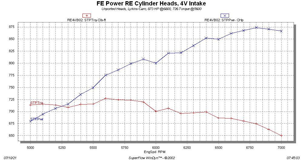
Next on the testing list is testing with the crossram intake manifold, then I'll swap back to the RE heads and repeat everything one more time. Based on the improvements I've seen with the SE heads, I'll bet the RE heads will peak right around 875 HP. Not 900, but pretty close, and not bad for heads that have not been ported.
I still have some work to do to to finalize, and potentially improve, the intake manifolds for this package. But at this point, I have beaten the living
SH*T out of the heads, intakes, and rocker arms, and I am quite confident that they will hold up well in a street or race application. So, I'm pulling the trigger on production as of today. This week I hope to get current quotes for the castings from the aluminum and steel foundries, plus some of the other vendors I need to get parts from, and then I'll be able to finalize pricing on the package. If you are on my list for one of the cylinder head packages, I'll be in touch with you in a week or so. Thanks again to the forum for all the support on this project, I really appreciate it - Jay


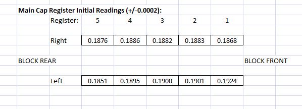
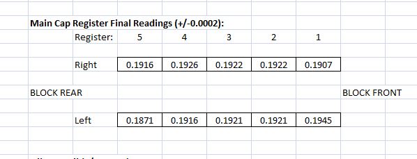
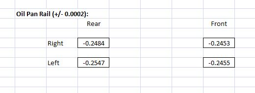
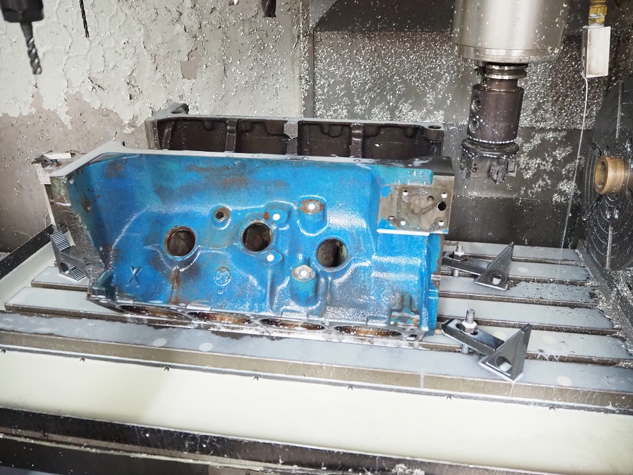
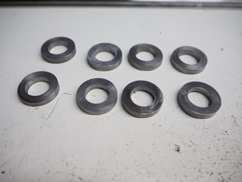
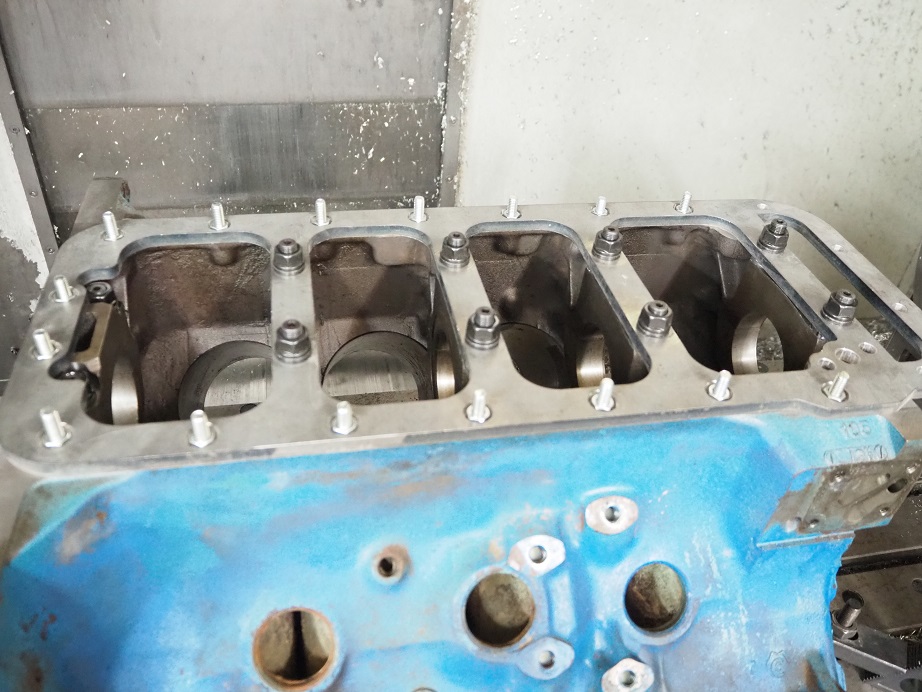
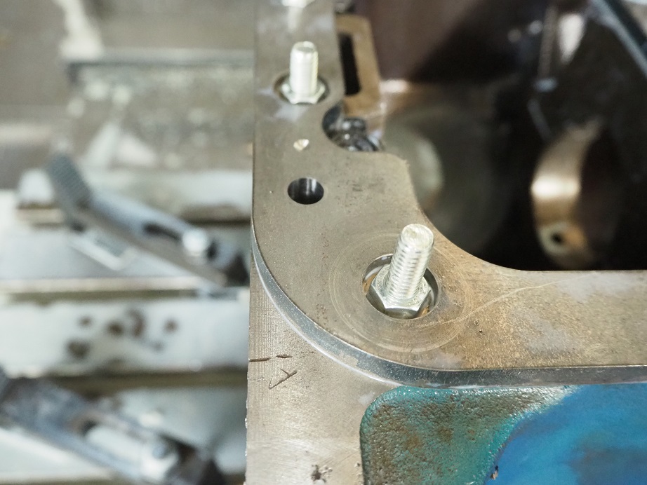
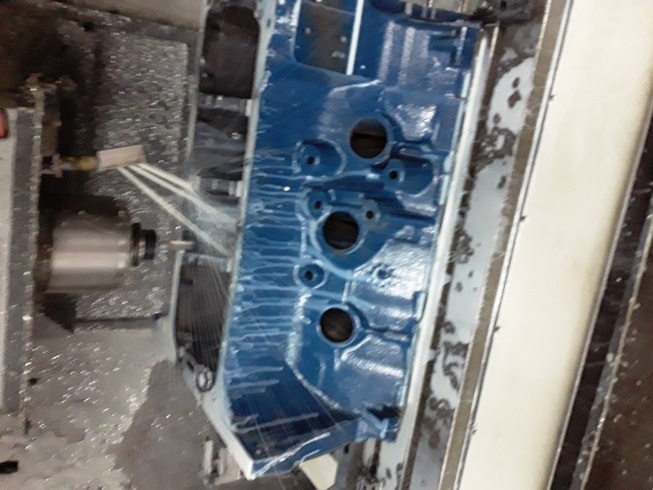
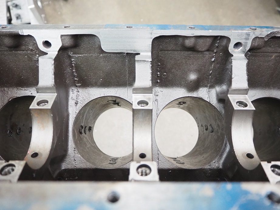
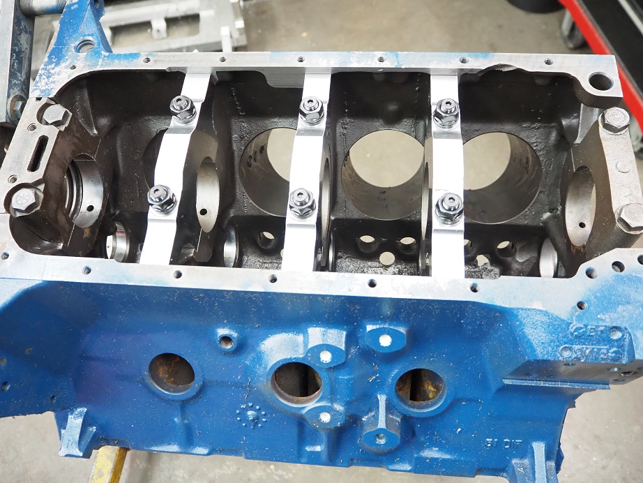
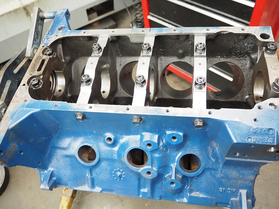
 Anyway, I had known about this issue and had the block owner buy some special, shorter studs for the #5 cap. To make the stud washers and nuts fit, I also counterbored the #5 cap 0.275". I installed the studs, the caps, and the spacers in the correct location to make them all the same height, then finally I installed the oil pan studs that came with the kit; here's a picture of how the block looked at this point:
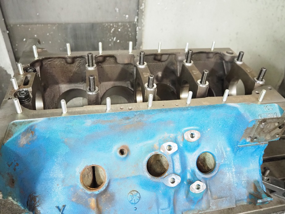


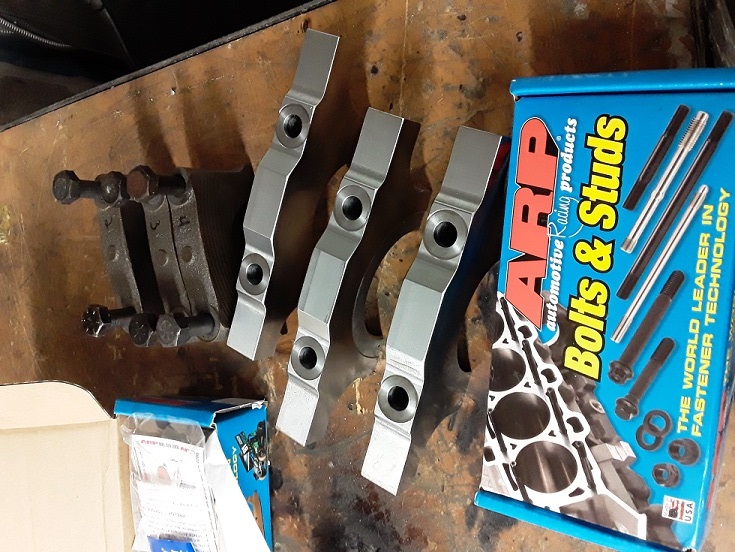

 ) I could see that the #4 exhaust rocker had broken. This was a Comp Cams rocker, one of the extruded aluminum ones that Dove used to make for Comp. They are known to fatigue and fail after a while, but I hadn't been too worried about this because the valve springs on this engine are pretty mild. Apparently that didn't matter to this particular rocker arm. The engine has been together since 2008, and I put a couple thousand miles a year on it, so I guess it doesn't owe me anything, but still...