Show Posts

This section allows you to view all posts made by this member. Note that you can only see posts made in areas you currently have access to.


Topics - jayb

Pages: [1] 2 3 ... 25
1
Private Classifieds / Ford FE Low Riser 2X4 Intake
« on: March 27, 2024, 03:19:45 PM »
Note:  I am posting this for one of our forum members - Jay

Ford FE Low Riser 2x4 intake manifold. Date code 3A2.  Part #C3AE-9425-H. It has not been ported or altered in any way.  It has never been media blasted either.  I ran it on my 390 for many years and have upgraded to a bigger motor.  No issues with it other than on the driver’s side top middle valve cover bolt hole, needs a helicoil as well as the thermostat housing bolts have had 3/8 threaded rod installed. I am including the draft tube cover, thermostat housing, fuel log and linkage. See attached pictures. Any questions please contact me. 

Shipping will be discussed if purchased and based on destination. Willing to meet in the twin cities area for pick up.

$2,000.00
Cash Only!!!!!!!!!!!!!


2
Starting to sell some of my stash of personal items.  This is a complete cylinder head package for an FE, with the best parts I could buy when I purchased them in 2006.  The heads are the Blue Thunder medium risers, the early ones, not the ones with the huge rectangular ports.  I purchased these CNC ported from Barry R at Survival, and used them on the supercharged engine in my Mach 1 that I ran at Drag Week in 2007.  I don't have flow data on these heads, but when I bought them Barry said they flowed around 360 cfm on the intake, and I have no reason to doubt him. 

Since the engine was supercharged I went with Inconel exhaust valves for durability, and normal stainless steel intakes.  I had the chambers and valves coated at Swain Technologies, and fitted the heads with springs that were much heavier on the intake due to the 17 pounds of boost I was running from the centrifugal supercharger.  The T&D rocker system, which is a dedicated system just for the Blue Thunder heads, uses the standard 1.75:1 ratio, with no extra offset on the rockers.  On the dyno, with an air to water intercooler, the engine made 1030 HP.  In the car, I couldn't get the intercooler to fit where I wanted, so it only made about 900 without it.

After Drag Week I had the heads gone through in preparation for reassembling the engine with them, but got bit by the high riser bug and went that route in the car.  So, these heads have been sitting in plastic since about 2008.  They have a new valve job, new surfacing, and several new valves because some of the old ones showed stem wear.  The ports were also cleaned up in order to remove the CNC tooling marks.  If you look carefully at the pictures you will see that the exhaust side of the heads has also been relieved about 0.100", in order to provide more clearance for the headers (Blue Thunder heads have the exhaust ports raised up just a little, so extra header clearance is good).

The valve springs, retainers, spring seats, and lash caps are included in this package.  The exhaust springs measure about 180 pounds at 2.000", and 520 pounds at 1.300".  The intake springs measure 280 pounds at 2.00", and 640 pounds at 1.300".  This is using my somewhat questionable spring rate checker; wouldn't surprise me if they were off a bit one way or the other.  The retainers are Comp Cams titanium retainers, and the spring seats are Comp steel seats. 

The T&D system requires oiling through the pushrods, so I am also including the pushrods that went in the engine.  Some of the pushrods have some rust spots on them that I've wiped away with WD40 and a Scotchbrite pad.  I would not hesitate to use them again, but you may be fussier than me.  There is one nut missing on the T&D setup; its got to be around here somewhere, but I have not been able to find it yet.  Also, when you purchase the T&D setup they provide washer-like shims that can go under the rocker bar, to adjust rocker geometry; I don't have those either, but they could be easily obtained at McMaster Carr.

This is all really top shelf stuff that I had more than $8K invested in when new.  I want $5500 for the package.  I will not separate it.  Shipping is extra.  I can take a personal check, and also a credit card, but if you use a card I will have to add 3.5% for the credit card fee I get charged.  Pictures are below.  You can message me here, email me at jayb@fepower.net, or call the FE Power number at 952-428-9035.    Pictures are below, and thanks for looking - Jay


3
Non-FE Discussion Forum / Calliope Engine Project
« on: December 21, 2023, 03:36:48 PM »
Here's a couple pictures of one of the coolest engines Ford ever built:


For those who don't know anything about this engine, here's a little background.  After winning LeMans in 1966 and 1967 in GT-40s with FE 427 engines, Ford was planning to go back to LeMans in 1968 with a new engine.  This engine was very loosely based on the new for '68 385 series engine, but had dramatic engineering changes compared to the production engine.  The engine had 2 intake valves and one exhaust valve per cylinder, and the valves were pushrod actuated with two different camshafts in the block, one cam with 16 lobes in the normal position to run the 16 intake rockers, and a second cam in the block above the first which ran the 8 exhaust rockers.  The exhaust pushrods ran horizontally from the cam to the exhaust rockers.   

Built into the cylinder heads were the injector stacks, so that no traditional intake manifold would be required.  The presence of the stacks apparently reminded Ford engineers of a calliope pipe organ, which is how the engine got it's nickname.  The bundle of snakes headers shown in the pictures were designed to fit the Ford GT-40 Mk IV chassis.  The engine also featured a dry sump system incorporated in the pan, which was claimed to provide crankcase vacuum in addition to oil pressure and control. 

The engine was 427 cubic inches in order to meet LeMans rules, but prior to the 1968 LeMans race, the sanctioning body outlawed 7 liter engines, making smaller engines mandatory.  As a result the project was stillborn after the rule change, and Ford corporate bailed on racing at LeMans (although independent teams won again with GT-40s in 1968 and 1969, running small blocks).  The Calliope engine itself disappeared from view for many years.  Apparently only two of the engines were produced, and only one is still existing, at the Ford museum in Dearborn.  Dyno testing by Ford back in the day showed the engine delivered 630 HP, which would have been a big step up in the LeMans cars compared to the FE engine.

My friend Dan Schoneck learned about the Calliope engine a few years ago and after asking a bunch of questions of various contacts, found out that the original foundry tooling for the engine was still in existence.  From what I understand the tooling originally went to Holman and Moody, and then was sold to a well known parts manufacturer on the west coast in the 1980s.  I don't have permission to reveal who had the tooling, but most of us would know his company.  In any case, Dan finally found out who had the tooling, and arranged to buy it all; he came back with it this past summer. 

Over the last 12 years I've developed a lot of foundry experience and tooling contacts, and this was one project I was very interested in getting involved in.  So after getting a look at the tooling Dan brought back, and figuring out what we had, I volunteered to bring it to my foundry's attention and see if they would be interested in casting it.  This was a bit of a sales job, because the volumes of this project were not going to be high, and working with tooling from the 1960s would certainly be a little risky, but I put together a presentation for the foundry and they were interested enough to give us the go ahead for casting the cylinder heads.  I also got my local pattern shop involved, because I know the owner there very well and he loves doing this kind of stuff.  The owner has years of experience designing the feed system which channels aluminum into the mold properly.  This is a critical part of any aluminum casting and was going to be required because the tooling was prototype tooling from Ford, and did not have sprues, risers, gating, or any feed system that normal foundry tooling has.  This meant that Ford originally cut all these features into the sand cores by hand.  My pattern guy has the experience to do the same thing, so he is an important part of the project.

Dan delivered the tooling to the foundry a couple weeks ago, and yesterday we got started on trying to pour a cylinder head.  The Ford tooling is super cool; most of it is hand made from mahogany, and each tooling box is labeled with a Ford XE number.  Apparently the XE number for the Ford Calliope cylinder head is XE-139612.  See the tags on the cylinder head end core box below.


Pictures of some of the sand molds are below.  This is the drag, which is the bottom of the mold:


The intake port cores are individual, and look like this:


The exhaust ports cores are all molded in a single piece.  It's interesting to see how the port widens out into an oval shape as it exits the head:


There are also cores for each end of the cylinder head, and the bottom of the intake runners.  We assembled all these parts on the drag to get a look at how it all fits together:


The core below closes over the top of the previous mold:


Then the cope, which is the top of the mold, is installed and the mold is ready for pouring.  Unfortunately, we ran into a problem with the Ford tooling when it came to the water jacket core.  This is a very complex set of three cores, with sand thicknesses down to around 0.100".  The foundry guys had trouble getting the sand packed into these molds by hand; our guess is that Ford had a machine to do that, which the foundry doesn't have.  Also, even if the mold got completely filled, there was difficulty getting the cores out of the molds without breaking them.  Pictures of the core box for the lower water jacket core is below, the second one showing the sand after the box was split back apart after filling.  In the second picture we are using glue to hold the sand core together after it broke coming out of the mold.


There are three water jacket cores like this, that need to be glued together and then set into the mold.  After spending hours just trying to get a good one, I suggested that we go to a 3D printed version, and make it a single core.  We are lucky that Dan has the masters for these cores (the masters are what the 3 finished cores are supposed to look like).  Dan is going to get them 3D scanned so that we have a file showing what the completed water jacket core is supposed to look like, and then we can get them printed in sand so that we don't have to fight with getting decent cores out of the Ford tooling.

Due to the issues with the water jacket we didn't get to pour a head yet.  Hopefully in a month we will be back at the foundry with water jacket cores so we can get some of these poured.  Of course, getting good castings is just the beginning of the work.  Next they need to be machined, which means machining fixtures will have to be made, and there will be some guessing on the where all the surfaces and holes need to be, because we don't have blueprints for the engine.  However, Dan has arranged with the Ford museum to be there and get a detailed look at the engine that they do have, so hopefully that will point us in the right direction.

The block is also going to be an issue, because a standard 429/460 block is nowhere near close to working.  The Calliope engine used Cooper rings for sealing the head to the block, and has no provision for water passages from the block to the head; instead, the water from the dual water pumps flows through the block to the back, makes a U-turn into the head at the back via an external fitting, and flows out of the front of the head.  Also, the head bolt locations are completely different; there are actually 8 bolts around each cylinder on the Calliope engine, and none of them are in the normal head bolt position in the block.  On top of all that, Dan is missing some tooling for the block, and we will have to go to a different foundry for the block because the foundry we are using can't pour a part as large as an engine block.  So, basically this is the beginning of a fairly long project, but Dan is committed to getting it done.  For my part, I just want to see one of these things running on the dyno ;-)

I will post updates on this project as they happen - Jay

4
Vendor Classifieds / FE Power Tunnel Port Cylinder Heads
« on: September 01, 2023, 09:06:46 PM »
See the link below for information on these heads.  I plan to place an order for a small production batch in early October.  With the current foundry schedule, I should have castings by Thanksgiving, they should be machined by mid-December, and then it will be off to my local shop for seats and guides; probably late January to mid-February for delivery.

Price will be $3400 per pair.  These will be bare heads, and they will require a valve job and all the valvetrain gear to complete them.  If you are certain you want a set, I will need a $1500 deposit to reserve a pair for you.

If delays occur and I am not able to deliver the heads within a year of receiving the deposit, I will return the deposit to any customers at their request.

If you don't want to provide a deposit (which I understand completely), you can just email or call with your contact info and I will let you know when I have a set ready.  However, I will not guarantee that you will receive a set anytime soon; I will probably only make a few sets more than I have deposits for. 

Any questions, feel free to email me at jayb@fepower.net, or call me at 952-428-9035. 

https://fepower.net/simplemachinesforum/index.php?topic=11821.0

5
FE Technical Forum / FE Power Tunnel Port Cylinder Heads
« on: September 01, 2023, 09:04:22 PM »
I've been thinking about this project for a long time, 10+ years.  In that time, no one has come out with them, so this past summer I decided that I was going to do it.  The back story on these tunnel port heads revolves around my cylinder head project. Last Spring, FINALLY, I started getting cylinder head and intake adapter castings from the foundry.  From March to June I received about 50 intake adapter castings and 50 cylinder head castings, both the SE and the RE versions.  Starting in late March I had the CNC machine running constantly, to try to get through machining all these castings, and by the end of June most of the heads that my customers had pre-ordered were at my local shop, waiting for seats and guides.  Unfortunately this is their busy time of the year, so only some of those have been finished at this point; nevertheless it's been a big step forward compared to the last two years.

The other good news was that the tooling for the intake manifolds for my heads was done, and they were scheduled to be poured at the foundry in mid-August. This left me with a little free time, and a schedule target to hit in order to sneak some heads in with the intake manifolds.  So with some encouragement from a couple good customers I decided to pursue the tunnel port project.

My SE and RE heads are set up with the same port location as a tunnel port, which gave me a huge advantage in designing my version.  Because of this I was able to use the cope and drag tooling for my heads to also do a tunnel port version, and only had to change the 3D printed sand core.  This saved a whole bunch of time and money, and accelerated the path to a completed head.  From July into early August I spent a lot of time on the computer completing the design, guided by a tunnel port head that I had here. I have tried to make my version as faithful as possible to the original Ford part, while making some improvements to provide a better overall cylinder head.

Pictures of the prototype head are below (Note:  behind the tunnel port head in a couple pictures are a bunch of raw castings for my SE and RE heads, which I just received a few weeks ago and which have not been machined yet; those are either going to people who have contacted me about getting some from the second production batch, or else going into inventory here).  The tunnel port prototypes are bare heads; I have not yet had a valve job done or gotten flow numbers, but I would expect that they will flow very similarly to the factory cast iron tunnel port heads.

Here are the changes I made to my version of the tunnel port heads.  Note that these heads would use the stock tunnel port intake manifold and rocker system, not a specialized system like my heads:

   - The floor of the intake port has been filled in, to reduce the port volume and also improve the short turn to the valve.  There is enough material in the casting to open the intake ports up to the stock size, if that is desired.

   - Modern combustion chambers are machined into the head.

   - The plug has been changed from an 18mm taper seat plug to a 14mm, gasketed 3/4" reach plug.  The plug location has also been moved.  Hopefully this will eliminate the cracking issue between the plug hole and the intake seat that the factory heads suffered.

   - The guides have been changed from 3/8" stem to 11/32" stem.

   - The exhaust bolt pattern has been changed to the Cobra Jet style.

   - Accessory mounting holes have been put on both ends of the heads, not just one end.

   - Large inserts have been put into the rocker stand bolt holes, to withstand more spring pressure.

   - The intake face of the casting has been thickened, to avoid the cracking on this face down near the deck that is often seen on the original heads.

   - One other modification that I may make, if some customers are interested, is to replace the exhaust port design (which is basically like most other FE exhaust ports), with the one from my SE head design.  This will make the casting around the exhaust ports look different than a stock tunnel port head, because of the shape of the port itself.  However, it would result in flow of around 250 cfm, rather than the sub-200 cfm flow of a standard FE exhaust port.

I will be displaying the prototype tunnel port head at the FE Race and Reunion September 7-9.   I am also planning to take advantage of the foundry's recent performance, and order a small production batch of tunnel port heads at the beginning of October.  The raw casting design needs a couple of tweaks, but I expect based on the prototype castings that they will come out looking good.  See the link below if you are interested in getting a set.  And as always, questions and comments are welcome - Jay

https://fepower.net/simplemachinesforum/index.php?topic=11822.0


7
Once again I have been wrestling some with forum issues, and this has led to delays in approval of membership applications.  Sorry for the problems.  They may be resolved now, but I'm not sure.  In any case, if you have to wait more than a few days for  membership approval, please email me at jayb@fepower.net to let me know.  Thanks for your patience - Jay

8
FE Technical Forum / 492" FE Dyno Adventures
« on: August 19, 2023, 04:39:32 PM »
The moral of this story is that you are never too old to learn  ;D

A little background:  Earlier this summer I finally got my 69 Torino Cobra (or Fairlane Cobra, or just Cobra, take your pick) on the road after paint and interior work.  I was planning to drive it as is this summer but after firing the engine, which had not been run for any significant time since 1976, two problems arose.  The lesser problem was that is smoked.  The greater problem was that the rear main seal was gone, and it pumped out a quart of oil every 60 miles. 

After about a week and half I got tired of smoking out all the nearby vehicles at stop lights and stop signs, and decided I needed to get a motor together for this thing.  I had been planning to repurpose the 492" FE used for the dyno testing in my book for this car.  It had been sitting on the engine stand since 2010, and when I uncovered it and pulled the heads and intake, I was really surprised at how good it looked.  I took a couple of rod caps off and the bearings looked like new.  I reviewed the last dyno results from 2010, and oil pressure had looked good, and no notes on problems, so I decided to just leave the short block together as it was, and rebuild it from there.

Joe Craine had ported a set of Edelbrock heads for me a few years ago, and they were sitting on the shelf and ready to go, so I used them.  I also grabbed a Performer RPM intake, since this was going to be a street only car, and had a couple of sets of Comp Cams solid roller lifters with pin oiling available, plus the set of Erson rockers that I had run on the engine previously.  Amazingly, I also located the original pushrods I had used back then, so those went back in the motor also.  Just needed a cam, and unfortunately due to various delays at Comp it took me five weeks to get one.  It finally came about a week and half ago, so I was able to get the engine together.

My good friend "Wild Bill" Conley happened to be in northern Minnesota visiting relatives this week, so he came down for a day to help with the dyno session.  Thursday afternoon we got the engine installed on the dyno and were ready to go by 6:00 PM or so.  Here's a picture of the engine on the dyno:


First thing I always do with a dyno engine is spin the engine with no fuel and use the timing light to set initial timing.  Unfortunately, the timing light didn't blink.   Hmmmmm....

I had been a little concerned about the ignition system on this engine.  The distributor was an MSD that hadn't been used for years.  Same with the wires, cap, rotor, and also the MSD Digital 6 box and the Blaster coil.  I had new Autolite Racing plugs installed, so I wasn't worried about those.  Bill and I started swapping parts.  We tried a different coil, a different MSD box, and new wire between the MSD box and the distributor, and finally we pulled the distributor itself and replaced it with another MSD unit.  Still no spark.

It was pretty close to 8:00 PM and I don't run the dyno after 8:00 in deference to my neighbors, so we called it for the night and took off to have dinner with my wife.  After dinner of course, we were still thinking about this.  Back in the shop, I was wondering about the MSD box.  It has a red LED when it is powered up with the ignition switch, and the LED was on.  Of course, it also has two big wires coming off it, one for 12V power and one for ground.  I decided to check the power there, and low and behold, zero volts!  Surprised the heck out of me; I figured that with the red LED on, the box had to have power.  But apparently, just the ignition power will light the LED, even if the main power wires are not getting voltage.

We figured out that a fuse on the main power line to the MSD box (that was conveniently out of sight under the dyno stand) had blown.  I replaced the fuse, and the engine started.  Too late to run, but at least we could get it going in the morning.

Before firing the engine yesterday morning we set it back up to the original ignition components, started the engine and started testing.  One thing we saw pretty quickly was that the ignition advance wasn't working, so we just locked the timing and ran that way.  A cruise test determined that we were way fat on fuel, which was not a surprise given the 1000 Holley HP carbs jetting (84/84, with 6.5 power valves in both metering blocks).  We jetted down to 76 in the primaries and then ran the first pull from 3000 to 5000 RPM.

The engine missed and pretty much ran like crap.  I had just rebuilt the carb so I wasn't too worried about that, so it appeared we had an ignition problem after all.  Again we went to swapping parts, changing timing, etc. but were not able to solve the problem.  Unfortunately Bill had to leave late morning, so we called the session off without a resolution.

I thought about this most of yesterday, and got back out to the shop this morning with a couple of ideas.  First I wanted to see the airflow into the engine recorded by the dyno.  This chart confirmed to me that the issue was ignition, because the engine was continuing to pump air despite the fact that the power was falling off:


Seemed like something was happening around 3900 RPM that was hurting the power production.  I went through the same steps as we had before, swapping coils, swapping MSD boxes, checking everything.  I thought I had found it when I pulled the distributor cap and tried to measure the resistance between the cap terminals and the contacts in the cap, and got very high resistance.  The contacts in the cap were pretty badly corroded, so I shined them up with some sandpaper and ran another pull, but there was no difference.  I checked the resistance of all the plug wires and got 80-110 ohms each, and about 40 ohms on the coil wire.  I looked at all the plugs and they all looked fine, pretty much brand new.  I was about ready to pull the distributor again when I thought it would be easy to just replace all the plugs and try that once too.

The new plugs were Autolite 3923 Racing plugs.  The old plugs I dug out of the coffee can were Autolite 3924s.  I replaced all the new plugs with the old used plugs, and the engine ran like new.  Here's a plot showing the difference, old used plugs vs the new plugs:


The new plugs were junk??  Looking at the graph, obviously, the plug issue was causing problems much earlier than 3900 RPM.  After running some more dyno tests I took the new plugs and measured their resistance.  The plugs in the #2 through #8 cylinders all measured about 5K Ohms.  The plug that had been in #1 measured 72K Ohms.  Obviously, that plug wasn't firing and the engine was running on 7 cylinders.

I'm not through with this engine yet, still have a ways to go tuning wise.  Right now it is making 596 lb-ft of torque @ 4500 and 580 HP @ 6100.  Compared to how it was outfitted in the dyno testing in the book, the heads are down in flow about 15 cfm on the intake compared to the original heads I used, and the cam is smaller, 256/260 @ .050 compared to the cam used previously, which was 266/272 @ .050.  Compression is down about a quarter point also.  I was hoping to get 600/600 out of this engine, but don't know if I will get there or not.  When I get done with it I will post the info in the Dyno Results section. 

Anyway, lessons learned:  The red LED on an MSD Digital Six does not indicate that the main power is connected, and brand new plugs can be faulty.  Go figure...

9
FE Engine Dyno Results / 482" FE Stroker, 582 HP, 581 Torque
« on: August 07, 2023, 09:53:15 AM »
Performance Summary:
      Cubic Inches:  482             Dyno brand:  Superflow 901
      Power Adder:   No            Where dynoed:  FE Power
      Peak Horsepower:  582
      Peak Torque:  581

Horsepower and Torque Curves:


Engine Specifications:
   Block brand, material, finished bore size, other notes:  Pond aluminum block, 4.25" bore
     
   Crankshaft brand, cast or forged, stroke, journal size:  Scat forged 4.25" stroke crank, BBC journals
     
   Connecting Rods brand, material, center to center distance, end sizes, bolts:  Molnar 6.700" BBC rods

   Piston brand, material (caster, hypereutectic or forged), dish/dome volume, static CR:  Mahle forged pistons, 11:1 compression

   Main Bearings, Rod Bearings, Cam Bearings brand and size:  Federal Mogul 351C 3/4 groove bearings, Clevite CB743 Rod Bearings .001 undersize, Durabond cam bearings for side oiler

   Piston rings brand, size, other notes:  Mahle thin rings, came with pistons

   Oil Pump, pickup, and drive:  Precision Oil Pumps HV pump, pickup for Cobra Pan, Precision Oil Pumps drive

   Oil pan, windage tray, oil filter adapter:  Cobra pan, Ford windage tray, Ford oil filter adapter

   Camshaft brand, type (hyd/solid, flat tappet or roller), lift and duration (adv and @.050")  Comp Cams hydraulic roller cam from Lykins Motorsports, 299/305, 243/252@.050, .610/.603

   Lifters brand, type:  Morel hydraulic rollers, standard (not short travel)

   Timing chain and timing cover:  Cloyes billet timing chain set, FE Power timing cover

   Cylinder heads brand, material, port and chamber information:  Trick Flow heads, out of the box, no porting

   Rocker arm brand, type (adjustable or non-adj), material, ratio:  Harlan Sharp rocker arm package, adjustable, stock ratio

   Pushrods brand, type, length:  Trend ball-cup pushrods, 3/8"

   Valve covers, brand, type:  Cal Custom, vintage

   Distributor brand, advance curve information:  Ford distributor with Pertronix, advance all in at 3600

   Harmonic balancer brand:  Professional Products

   Water pump brand, type (mechanical or electric):  Edelbrock mechanical

   Intake manifold brand, material, porting information:  Ford tunnel wedge intake

   Carburetor(s) brand, type:  Ford Holley carbs, 650 cfm, AC/AD (I think)

   Exhaust manifolds or headers brand, type:  Hooker competition plus


I have a local friend with a 57 Ford that has been equipped with a 428 forever.  He has been looking to upgrade the engine package so he came to me to help put it together.  This has turned out to be a long project, because of block availability.  We waited for over a year to get a BBM block and never could get one, so this spring he decided to go forward with a Pond aluminum block for this engine. 

At the machine shop the Pond block required pretty much all the finish machining, including align honing the main saddle and cam bearing bores, and sizing the lifter galleries.  Once that was finished we were finally able to get going on the assembly, with the parts specified above.  This was my first experience with Trick Flow heads, and I must say I was impressed.  Looking at the intake ports, they get pretty small in cross sectional area inside the port, but the short turn is much improved over a stock or Edelbrock/BBM heads, and this showed up in the torque production.  The engine went together without too much trouble, although the block did require 351C main bearings (FE main bearings wouldn't fit), and the connecting rods measure big on the big end with standard size bearings, so I had to go with .001" undersized bearings.

My friend wanted the engine to look more or less stock, so he had me paint the block and heads Ford dark blue.  Almost killed me to do that LOL!  Here's a picture of the completed engine:


We got the engine on the dyno this past weekend.  We were hoping for 600 HP but didn't quite get there.  However, we also didn't try some of the standard tricks, like spacers, and despite the high RPM nature of the tunnel wedge intake the torque curve was very impressive.  So, as a street car this thing is really going to work well.  We started off with 110 octane race fuel and sneaked up the timing curve and RPM range until we got to 33-34 total and just over 6000 RPM.  However, starting at about 6100 RPM, the engine power fell off a cliff.  Something with the valvetrain was going on there, and my suspicion is either the hydraulic rollers are pumping up and holding the intake valves off the seat, or the valve springs aren't up to the drill.  In any case we decided to limit future excursions to 6000 RPM.  Certainly 600HP would have been achievable at higher RPM, based on the known performance of the tunnel wedge intake.

I want to address an issue about dyno data here, because this engine provides a good example.  Most dynos and/or dyno operators will take advantage of the smoothing function available with the dyno curves.  This function will mathematically modify the dyno data to make the curves look smoother, taking out the normal ups and downs of the torque measurements.  Below I have posted two plots of the dyno results we got when running the engine to 6300 RPM.  The first curve is the actual dyno data, and the second curve is mathematically generated from the actual data using the dyno's smoothing function:


It is clear from the first chart that something fairly dramatic is happening to limit power in the engine after 6100 RPM.  But, from the second chart, not so much.  The curve looks smoother in the second chart, which is what most dyno customers want to see, but it is hiding a serious engine issue.  I've mentioned this before elsewhere, but I always use the actual dyno data, not a smoothed curve, because the smoothing tends to hide problems.

This was designed to be a pump gas engine, so after running on the race gas to get the carbs and ignition dialed in, we backed the timing down 6 degrees and put in some 91 octane non-oxygenated pump gas.  We ran the engine several times, sneaking up to 32 degrees total on timing, and the engine performed nearly as well as it did on race gas.  We could have put a couple more degrees in it, but we decided to stop at 32 total to stay conservative.  Here's a chart showing the comparison between the pump gas and the race gas:


The last thing we tried was to add the oval air cleaner.  This cost some power, but not as much as we were expecting it to:


Overall  a successful dyno session; the engine ran beautifully and it was on and off the dyno in a few hours.  Coming up tomorrow I am doing another one of these 482" engines, but with some old Ford heads and a factory 427 block.  Following that I will be running one of my engines, a 492" engine with ported Edelbrock heads and a solid roller cam, to go in my Fairlane Cobra.  It will be interesting to compare the outputs from all the different motors...

10
FE Technical Forum / Turn Signal Conundrum
« on: June 15, 2023, 09:52:11 AM »
I'm having a turn signal issue on my 69 Cobra.  I had originally installed new bulbs in the taillights and front turn signal/marker lights, and when I finally got the battery installed last week I checked the operation, and found that the emergency flashers worked fine, but the turn signals did not come on, in either direction.  I swapped the flasher units, and had the same issue; all emergency flasher lights worked, but nothing on the turn signals.  After checking for power and confirming that the turn signal circuit had power (it is on a separate fuse from the emergency flasher circuit), I decided to upgrade the whole mess.

I bought a new turn signal switch (which is where I figured the problem was), new flashers that were LED compatible and also compatible with a combination of LED and incandescent lights, and new LED lights for the taillights, turn signal/marker lights, and the turn signal indicators in the hood.  The only remaining incandescent bulbs are the indicator lights in the dash.  Got it all back together a few days ago, and now the emergency flashers still work fine, and now the turn signal lights turn on, but they still don't flash.  Again I swapped the flashers and got the same thing, again checked the power going to the turn signal switch and confirmed it was good, but still no turn signal operation.

Now normally if you have lights that turn on but don't flash, you have a bulb out.  But all of the bulbs work, with the emergency flashers operating and with the turn signal switch in both positions.  I'm thinking a ground could be a problem, but the lights have always been bright, even with the original incandescent bulbs, and since the emergency flashers work perfectly, it doesn't seem to me that a bad ground is the issue.

I've gone to the trouble of getting a complete wiring diagram for the car, and have traced all the wires, and everything looks to be where it is supposed to be.  Any ideas on this?  Thanks for any comments - Jay

11
Hope everyone is having a great holiday season, and looking forward to smoking the tires and revving the FE in the coming year - Jay

12
Vendor Classifieds / New CP Pistons for 4.375" Bore
« on: December 08, 2022, 02:37:03 PM »
Long story short, I had these made for one of my cylinder head customers but then he got a cancer diagnosis and had to bail on the project.  I kept them for another project for a local friend of mine, but after waiting over a year for a BBM block he finally bailed on that and got a Pond aluminum block.  The Pond aluminum blocks won't go this big on the bore, so these pistons are now available.  They will work on any aftermarket iron block, or a Shelby big bore aluminum block.  They are too big for a factory iron or Pond aluminum block.  They will also work with any FE cylinder head, including the FE Power heads.  A picture of the spec sheet is attached, but basically they are for a 4.25" stroke, 6.700" BBC rod with 0.990" pins, are 11:1 compression, and use 0.9mm steel top ring, 0.9mm Napier second, and 3mm standard tension oil ring.  The pistons, pins, and rings are included.

My customer originally paid >$1500 for these parts; selling them for $1050 or best offer.


13
FE Technical Forum / Need Advice on Fox Body FE Project
« on: September 17, 2022, 11:00:59 AM »
So I'm looking to get back to Drag Week, hopefully next year, and want to race in the Street Race BB/NA class.  This class does not allow body modifications, and suspension mods have to be bolt on replacements that attach to the factory mounting points on the chassis.  The class also has a 3200 pound minimum weight with driver, and an ET limit of 8.50 or slower.

I want to go with a wedge engine that has my cylinder head package on it, and I want to be competitive.  That means I need to hit or be very close to the minimum 3200 pound weight.  Especially in light of my own ~240 pound weight, no way I can get my Mach 1 close to the minimum.  Not sure I'd want to strip out the stock interior and do other lightening tricks on that car anyway.  My Galaxie and my Shelby clone both have modifications that would prevent them from running in the class.  So, if I'm going to do this, I need a new race car  ;D ;D  The wife may not be pleased, but oh well...

A Fox body Mustang is an obvious choice, but I just don't want to be like everybody else.  At the FERR, I was talking to Rory McNeil and he suggested a 78-83 Fairmont or Mercury Zephyr, which is also a Fox body platform.  They are kind of plain Jane and boxy, but they are light, something like 2700-2800 pounds curb weight.  So with some work I think I could get one ready to race right at the 3200 pound limit.  They also have that trunk overhang, that the Mustangs don't, which should make it easier to hook the car with the smaller tires that will fit inside the stock rear wheel opening.  The cars are a little difficult to find, apparently the LS crowd is snapping them up, but they made a lot of them so I think I could probably find one if I looked hard enough.

My problem with these cars is that I don't know anything about them.  So if anyone could help with the following questions I'd appreciate it.  Most of these questions are just about where to source the components that I need:

- Is one year in that 78-83 model run preferable from a racing standpoint?  I know the 2 door sedans are probably lightest, but I'm leaning towards a 2 door Futura.

- I'd be looking at a tubular K member to save some weight, and run aftermarket front suspension components.  I've looked at quite a few K members online, but haven't seen any that are set up for an FE.  Is there such a thing?  If not, can one for a small block Ford be modified to work?

- I would plan to run subframe connectors along with a full cage.  All the subframe connectors I've come across are for Mustangs, which are too short to fit a Fairmont.  Does anyone know of a source for Fairmont subframe connectors, or do I have to fabricate those?

- How about fiberglass hoods and bumpers for those cars (which are legal in the class), are they available?

- Where can I get a 9" rear end housing that has the proper suspension attachment brackets already welded on?  I don't want to try that myself on this rear suspension, and all the rear ends I've seen online are complete units.  I prefer Mark Williams axles and their aluminum case, and I happen to have a case already, so I don't want to buy a complete rear end.

- Is there a preferred source for the front suspension components, given a drag race application?

- The class allows minor welding to the chassis for strengthening purposes.  Are there some points on the chassis that could or should be reinforced for a drag application?  Perhaps around the factory rear suspension arm mounting points?

I'm sure more questions will come up.  Thanks in advance for any info - Jay


14
FE Technical Forum / FE Power Intake Testing
« on: May 12, 2022, 10:42:30 AM »
I apologize in advance for this extremely long post, but there is a lot of information I wanted to share here.

It has really taken a long time to get all the intake manifold development and testing finished for my cylinder head project, much longer than originally anticipated.  It all started back in 2020, so it has been over a year and half to get everything finished up.  The scope of the work has changed along the way, to include a complete revamp of the rocker arm system (from aluminum to steel), and the original plan for building three intake manifold options for the cylinder head package has morphed into at least five, and probably six, intake manifolds that will be offered. Nevertheless, at this point I'm pretty happy with where everything stands, and will be going to production tooling on the intakes very soon.

A quick word about the dyno mule.  This engine has been a real trooper.  It has been through tremendous abuse, starting with all the broken aluminum rocker arms and related bent pushrods that showed up in the original test program, followed by a refit using the steel rockers, plus an update to the steel rockers to move from 3/8" adjusters to 7/16", and make a couple of other minor tweaks.  It has endured one major and two minor plastic manifold explosions that ruined the plastic manifolds and in one case blew shards of plastic shrapnel all over the dyno room and into the cylinders of engine itself.  It has seen uncounted hours of running, and a total of 254 dyno pulls, many of them to 7500 RPM.  And it is tired; the right bank looks pretty good with all the cylinders showing 170 to 180 psi of compression, but #5 is down to 140, and #6 is down to 80 psi.  Even so, the engine is still making 885-890 horsepower with the original 8V intake manifold.  It has been a kickass engine.

After multiple redesigns and lots of testing, I've tentatively settled on building two 4V intake manifolds, two 8V intake manifolds, a tunnel ram and the IR crossram intake.  I've put pictures and dyno data for each one below, so that they can be compared.  All the data shown is with the dyno mule fitted with the RE version of the cylinder heads, and 2-1/8" dyno headers.  Based on some back to back testing, the SE version of the heads will be down about 15-20 horsepower from the RE version.

4V Intakes:

The picture below shows the original 4V intake, that was cast at a local foundry.  My dyno junky friend Royce nicknamed this one "Rasputin", because it was tall and terrible!  This one ran originally on the engine with the aluminum rocker arms, and after discontinuing testing to update the rocker arm system it was sent down to Joe Craine for a little porting tune up.  After getting it back it was tested again with the new steel rocker system, and made a little more power than it had originally, so the revised design will be incorporating the changes Joe made.  Also, this intake was originally designed to split in half for easy porting, but Joe didn't think that was necessary due to the easy access to the runners, so for production this one will be a single piece design:


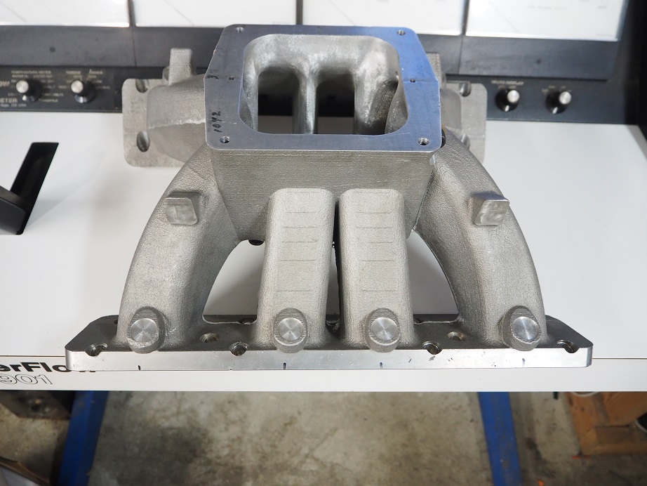
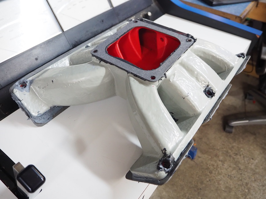
After testing the previous intake I had a couple customers contact me, wondering about hood clearance.  This intake of course was not going to fit under anyone's hood, not even with a CJ or Boss 9 scoop.  So I decided to take a stab at another 4V intake design, with an eye towards making it fit a car with a Mustang shaker scoop.  Because of this the carb mounting point and slant of the carb pad was positioned in the same place as a factory 428CJ intake.  Due to the height of the head ports, this intake was going to be 2" higher than the factory intake no matter what.  However, if a low profile EFI throttle body was used, based on the height calculations the shaker scoop would still fit. 

The 3D printed manifold pictured below is the second version that I designed (Note in the second picture that the manifold plastic has been painted; more on this later).  The first one did poorly on the dyno, making only about 770 HP on the dyno engine.  After revising the runner design, the one pictured made 825 HP, and with a 1" spacer it went all the way to 848 HP at 7100 RPM, which was down only a small amount from the tall 4V intake. I think this manifold would be a really good compromise for someone looking to maintain the stock hoodline of their car.


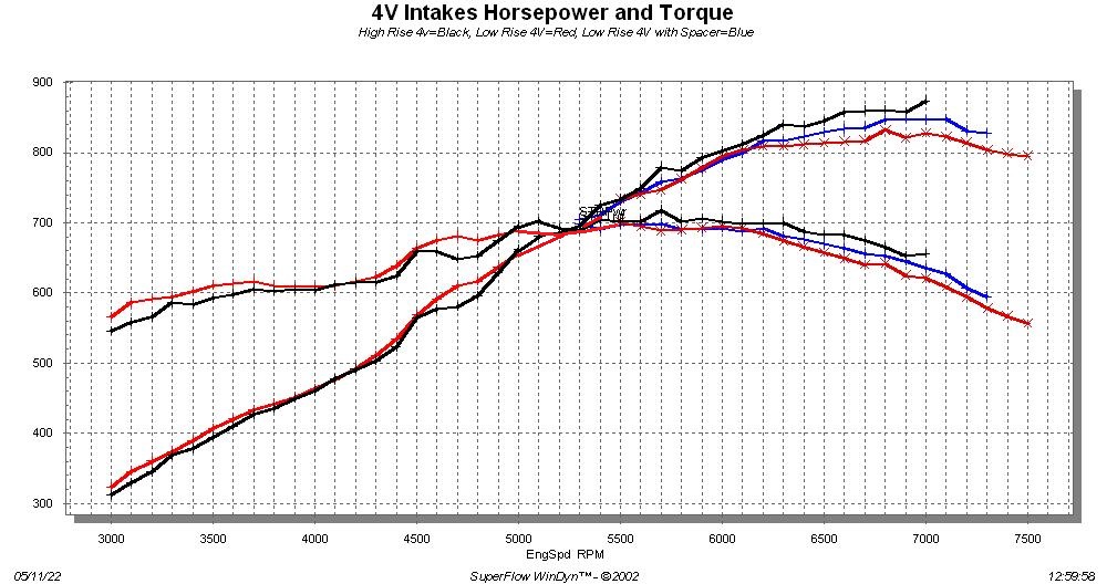
The graph below shows horsepower and torque from tall 4V, the short 4V with no spacer, and the short 4V with a 1" spacer (3000 to 5000 RPM with the spacer is nearly identical to without, and is not shown in the graph).  All the dyno graphs shown in this post have been standardized with a torque and horsepower range of 300 to 900, in order to make comparisons easier.


8V Intakes:

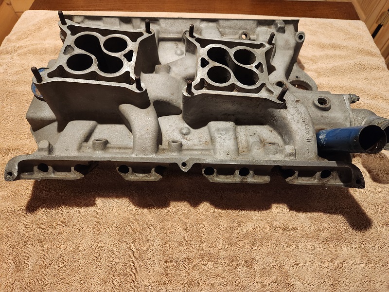
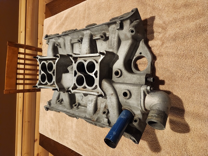
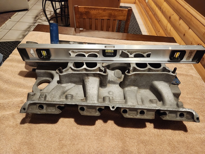
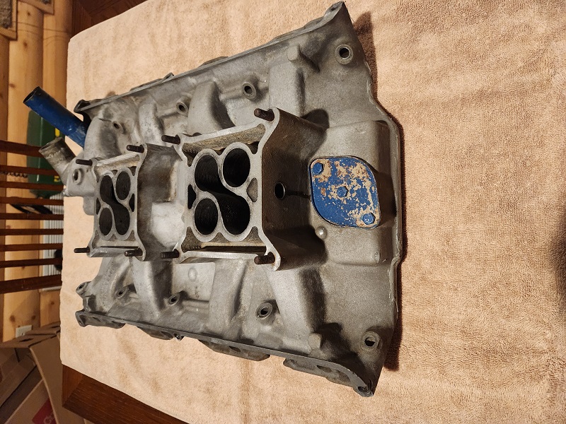
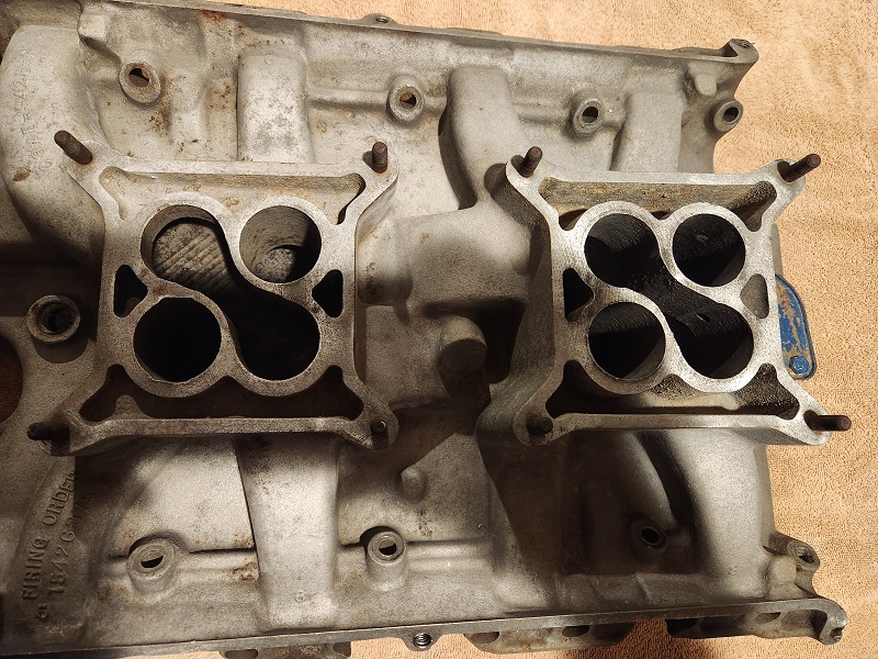
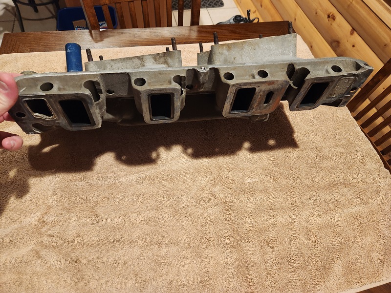
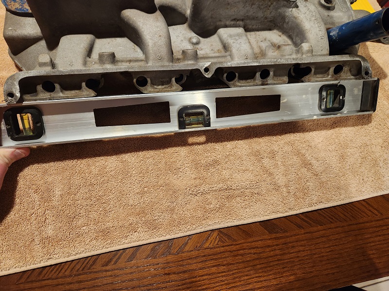
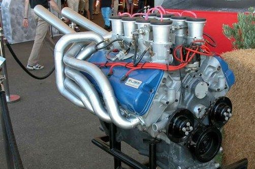
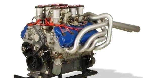
Similar to the original 4V intake, I designed the original 8V intake and had it cast at my local foundry, then had Joe Craine tweak it for me before I ran it with the revised steel rocker arm system. To date, this manifold has performed better in horsepower production than any other manifold I've tried, and that includes two sheet metal style intakes and two tunnel wedge style intakes.  It is not clear to me why this manifold works so well, because from a pure design standpoint it is a compromise.  One thing I've learned over the years of testing though is that the engine wants what it wants, and sometimes it is not predictable.  Like the tall 4V intake, Joe's changes will be incorporated into the production version.  Also like the tall 4V, this manifold was originally designed as a two piece intake, but will be a single piece in production.  Pictures of this intake are shown below:


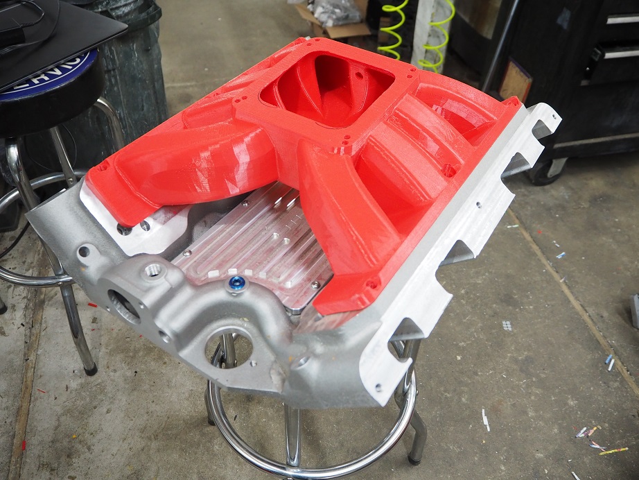
In order to make peak power I really wanted to try a sheet metal style intake on this engine.  Long ago when I bought my 3D printer, I had envisioned printing plastic intake manifolds and testing them on an engine, and I did this quite a bit during this intake development.  Of course, there was a learning curve.  The manifolds come off the 3D printer looking beautiful, perfectly formed runners, nice radiuses where they were designed in, etc.  They look and feel solid, but actually the outer layers are only about .060" thick, and the interior portions are a honeycomb-like structure.  One thing I learned the hard way is that despite their appearance, they are not airtight.  Below is a picture of the first sheet metal style intake I printed and tested on the dyno.  Royce nicknamed this one the Red Devil:


The name turned out to be oddly clairvoyant.  When the engine was started with this manifold installed, it didn't seem like it was running right.  Little did I know that there was a massive vacuum leak, right through the plastic of the manifold.  When the throttle was advanced, the engine backfired and blew the manifold to smithereens!  Picture of the aftermath is below:


The explosion caused a loud bang and a blinding flash, and blew both the Dominator carbs over the left valve cover, hanging by the fuel lines and on fire.  We got the fire out quickly so no damage.  Within 20 seconds we were all laughing our butts off over this deal; holy crap, the explosion and resulting fireball was SPECTACULAR!  If there had been a camera running in the dyno room when that manifold exploded, the video would have a million hits on youtube by now.

Anyway, this stopped testing for a bit while the engine was pulled apart looking for problems.  We found shards of plastic in all the cylinders, some of them stuck down between the piston and the top ring, but no other damage.  Put the engine back together with the aluminum 8V intake, and it made the same power as before, so no problems there.  From that point forward, after 3D printing a plastic intake, it was painted it with two coats of garage floor epoxy paint, to make sure that it was sealed before installing it and testing it on the dyno.

Two more sheet metal style intakes were designed, and were tested on the engine.  One had fairly short runners and a fairly large taper in the runners (first picture below), and the other had longer runners and less taper (second picture).  Neither one of them made close to the power of the 8V intake that had been originally designed.  The first one was tested several months ago, and the testing went fine with no issues (I am now extremely cautious when starting the engine with a plastic intake).  The second one was the last intake tested, just on Tuesday this week, and after three dyno pulls it was clear it wasn't going to get close to the 890 HP the original 8V was making; it was only getting to 860 HP at 7000 RPM.  That one looked like it might go a little higher than 860 HP if we ran the engine to 7500 RPM, but inexplicably when starting the engine the last time for that pull to 7500 we had a minor backfire and that broke the sides out of the intake.  The plenum portion of the tunnel ram intake also broke due to a minor backfire when it was tested the first time; the conclusion is that the bigger the plenum, the bigger the volume of air/fuel mixture ready to ignite, and the shorter the lifespan of the plastic intake!


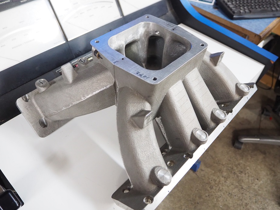
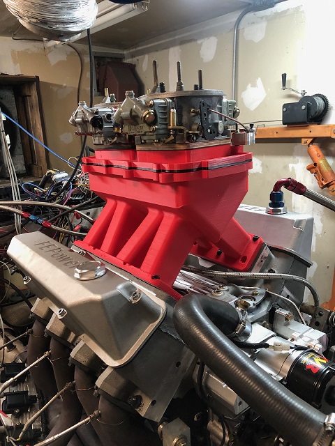
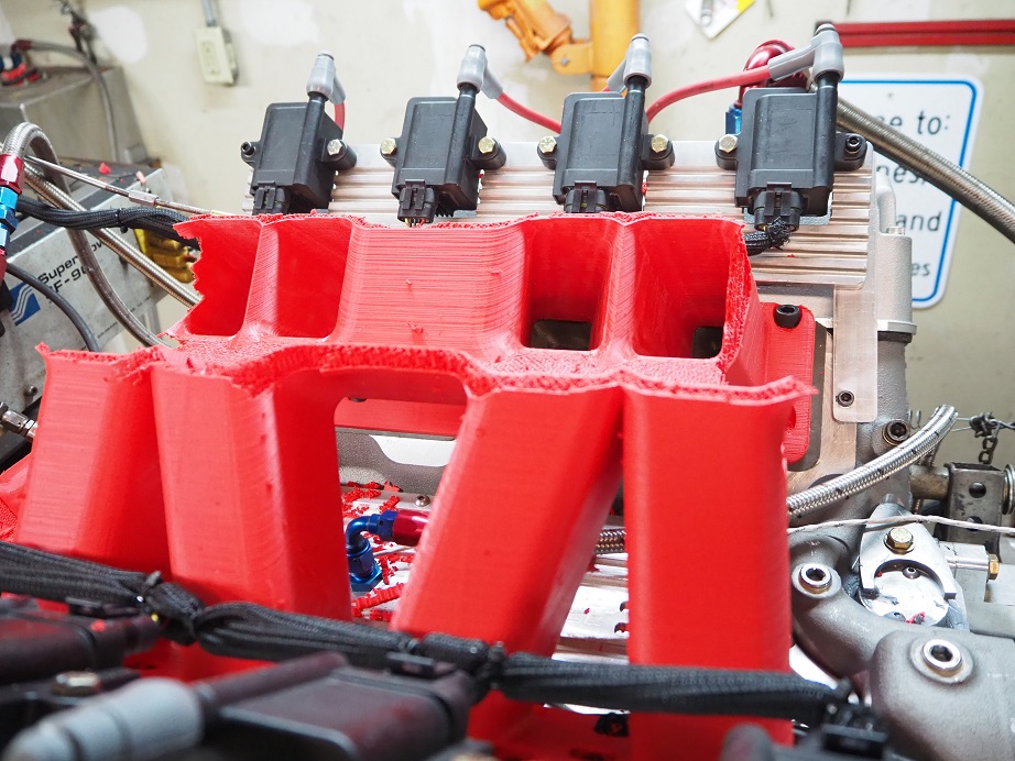
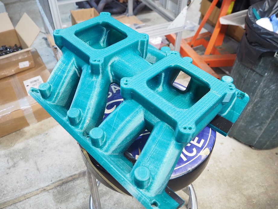
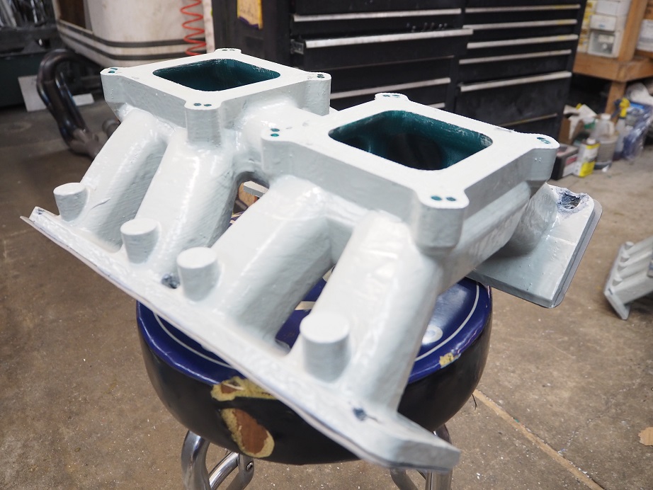
One other intake that I really wanted to do was an 8V intake that looked kind of like a factory tunnel wedge manifold.  Three 3D printed versions of this one were completed.  The first one gave disappointing results, only about 825 HP on the dyno engine.  So back to the drawing board where the runner shapes were redesigned, and also raised a little bit.  After 3D printing that one a mistake was found in the design of how the runners blend into the plenum; sometimes it's hard to see all the potential issues with a design by looking at it on the computer.  Back in one more time to fix up the blending issues, and then that manifold was printed, painted and tested.  The extra effort was rewarded with 875 HP from that one, and still climbing at 7000 RPM.  Pictures of the final tunnel wedge version, in raw plastic and painted, are below:


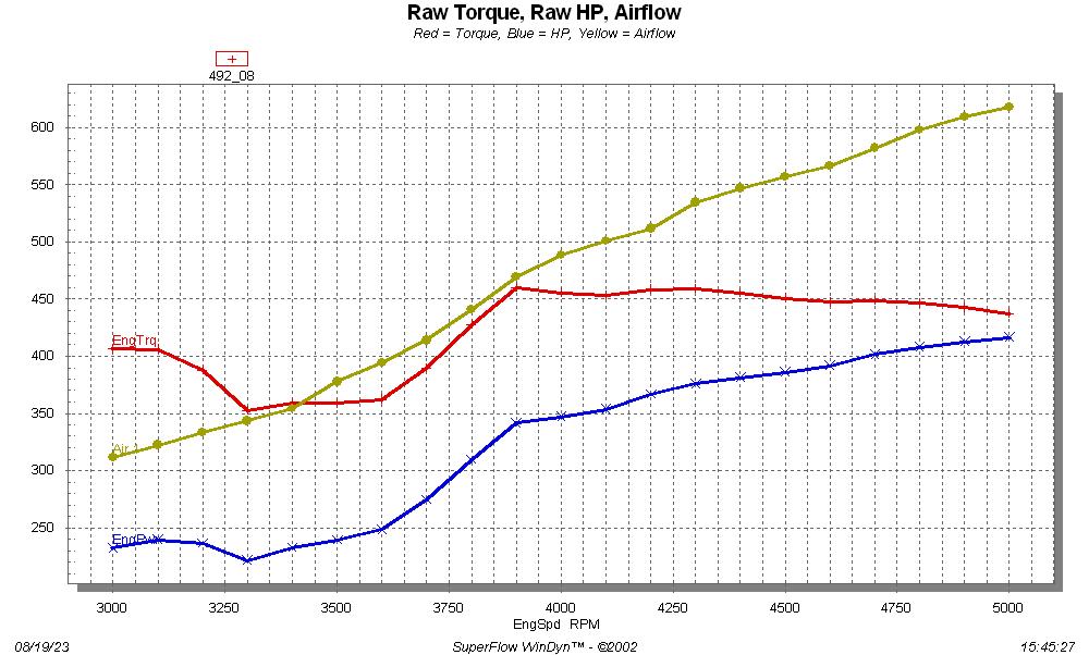
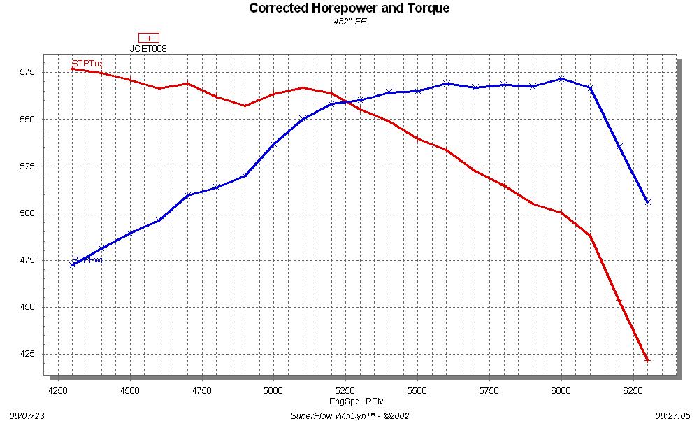
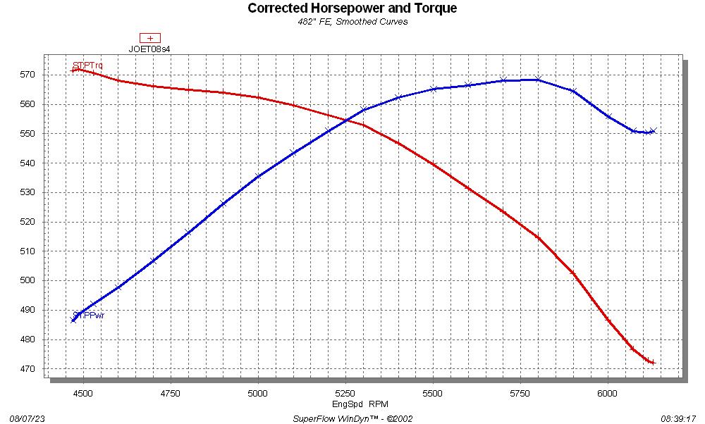
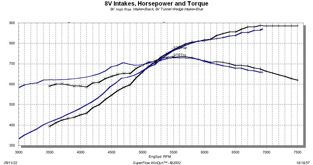
Dyno data for the 8V High Rise and 8V Tunnel Wedge manifolds is given below.  The 8V high rise makes more top end power than any of the other intakes, and holds in the 885 to 890 HP range from 6800 all the way to 7500, which to me is quite impressive.  There were a couple of pulls with the 8V high rise that netted 894 HP, but the data was a little questionable because the peaks were at one engine speed only, so those pulls weren't included in this data.  We thought with a little tweaking we could get this manifold to 900 HP, but nothing we did seemed to help.  I went so far as to wrap the headers, but got no change in power.  Then I built a whole new set of headers, with 2-1/4" primaries, and actually lost 5 HP on the top end.  I tried different jetting, different valve lash settings, etc., with no change.  I stopped short of actually running the engine at a really cold temperature, and icing down the intake, because I figured that would be cheating  ;D  So despite my best efforts I didn't get this engine to 900 HP.  I did not try a higher ratio rocker, which may have gotten it there.  There is also have another cam to try, specified by Chris Padgitt at Bullet Cams, but that one hasn't been installed yet.  This engine needs to be freshened up, before we get back to flogging it with a new cam and springs, higher ratio rockers, and ported versions of the heads; as mentioned before, the heads on this engine are unported.

The 8V tunnel wedge manifold makes better power than the 8V high rise at the lower engine speeds, and appears to still be climbing at 7000 RPM and 875 HP.  Hindsight being 20/20 this one should have probably been run to 7500 RPM too, but the results were satisfactory up to 7000 so it was left at that.  I was putting my bets on the tunnel ram...


Tunnel Ram and IR Crossram Intakes:

These two manifolds are torque monsters, beating the best of the 4V and 8V manifolds by a good 30 foot pounds of torque, which is an amazing 1.5 lb-ft per cubic inch.  I have never had a naturally aspirated engine that makes that kind of torque per cube on my dyno before.  The Individual Runner Crossram manifold had been planned since the very early days of starting the cylinder head project, but for some reason it never dawned on me to build a traditional tunnel ram.  I don't know why; a very large percentage of the people who purchase my intake adapters for their FEs use a Weiand tunnel ram on them.  Seems like FEs and tunnel rams go together. 

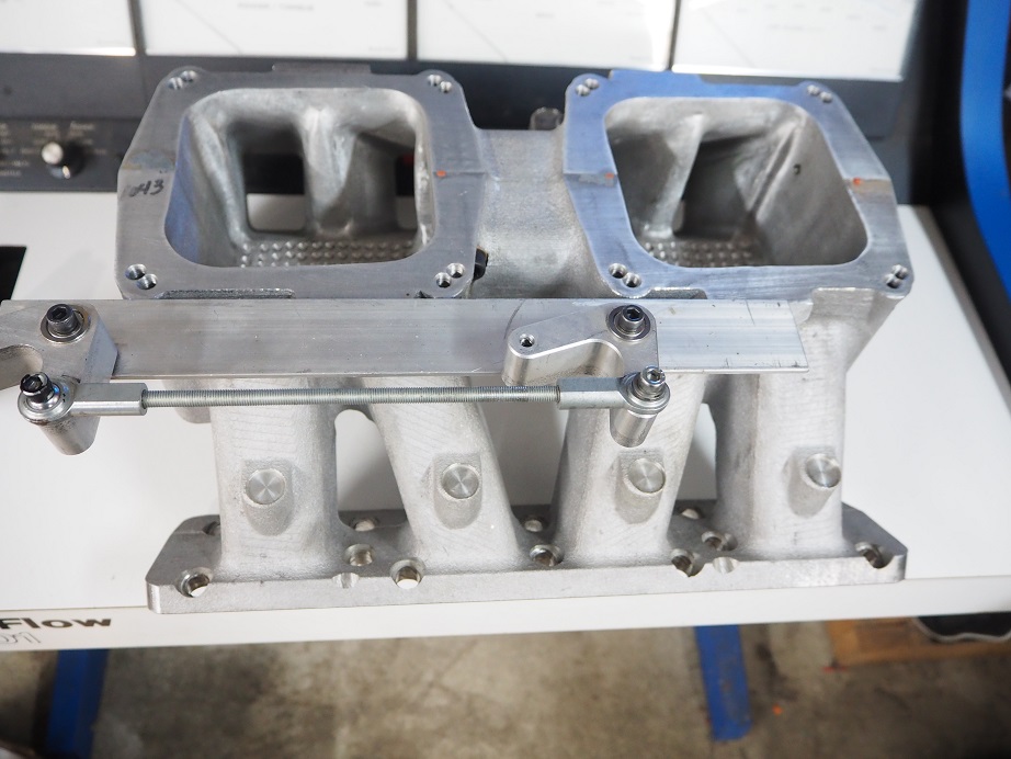
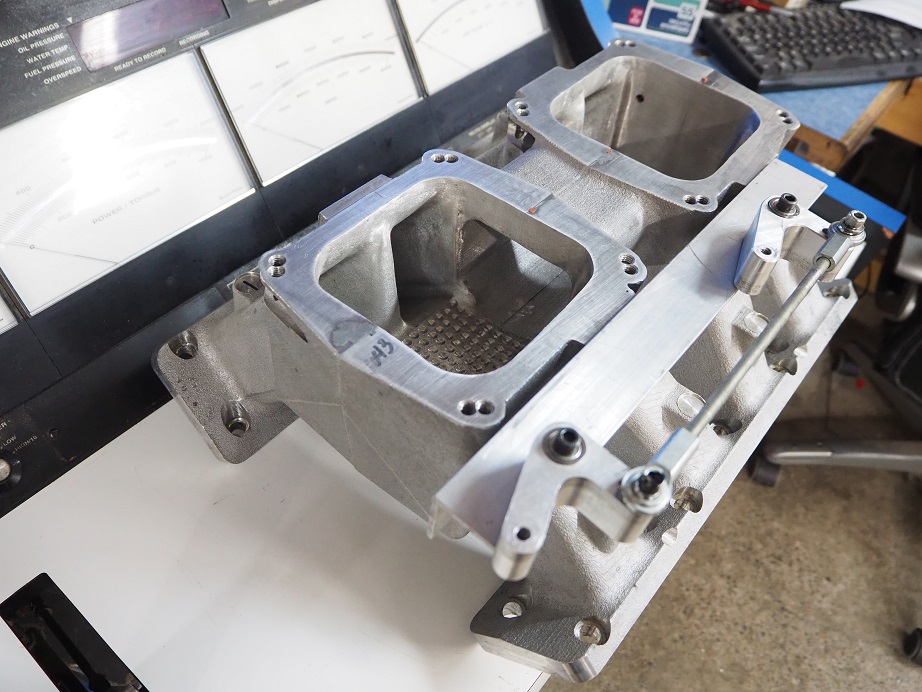
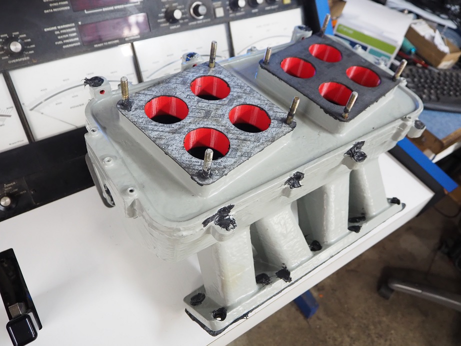
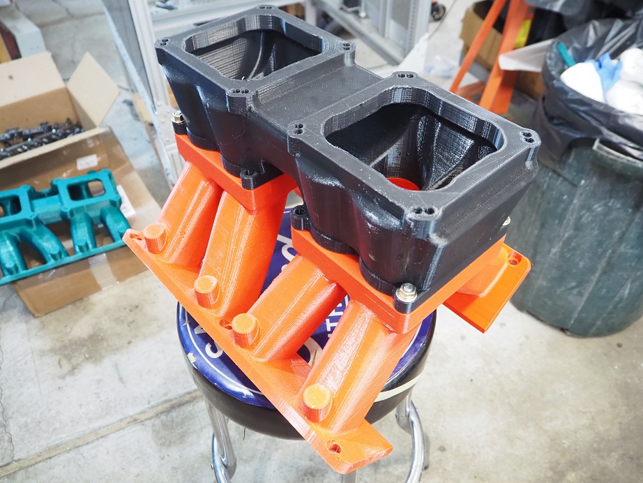
Anyway, I finally wised up and designed a tunnel ram intake for the cylinder heads.  Pictures of the intake are below.  I took a lot of the design cues from the Weiand 351C tunnel ram, which works extremely well.  It was 3D printed, then displayed at the FE Power booth at PRI this year.  In March Royce the Dyno Junky drove up, and we tried to test it, along with a couple of other intakes.  As mentioned previously though, a minor backfire cracked the plenum part of the intake, so no testing was possible.  A couple weeks later I had reprinted the plenum area and bolted it back on to the base.  This time the testing went perfectly, and I was blown away by the 763 foot pounds of torque that the tunnel ram made.  But like a lot of tunnel rams, it didn't pull all the way to 7000 RPM.  It peaked in the 6300-6500 RPM range, at about 865 HP, and then fell off.


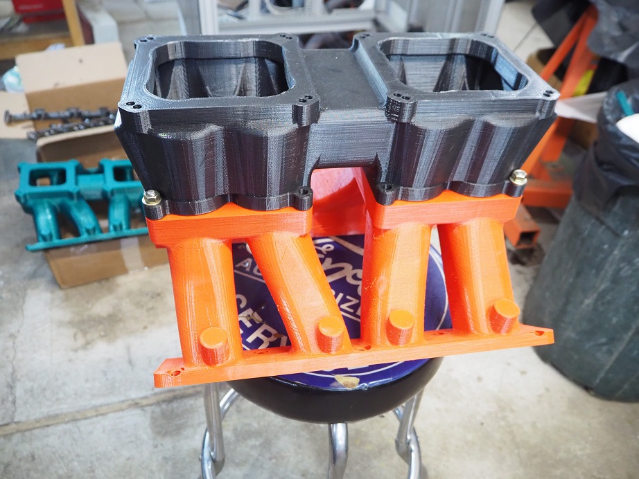
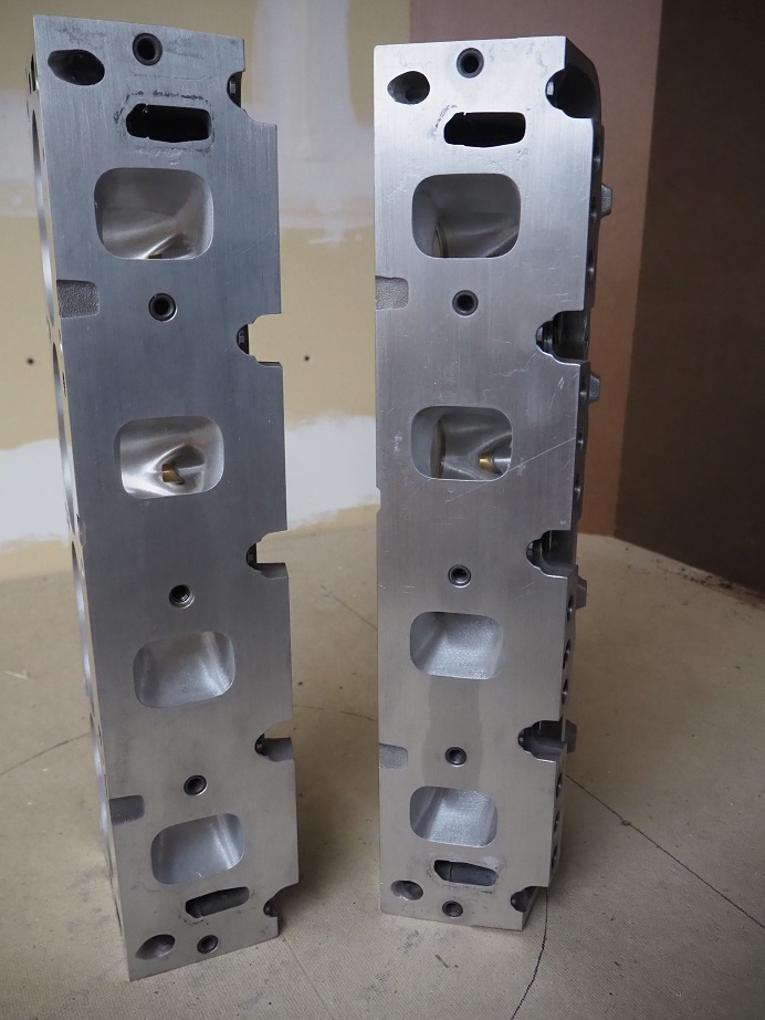
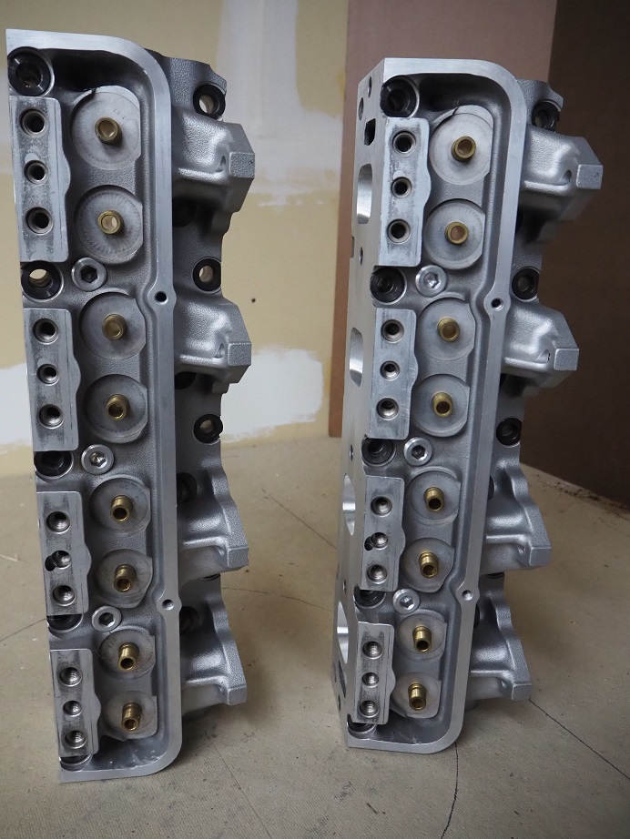
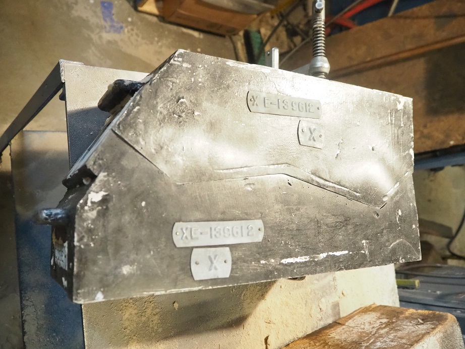
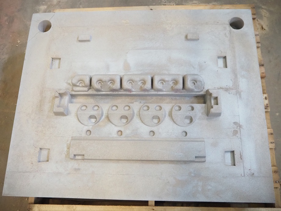
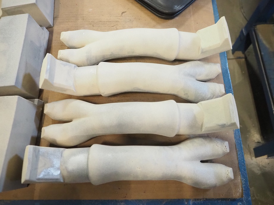
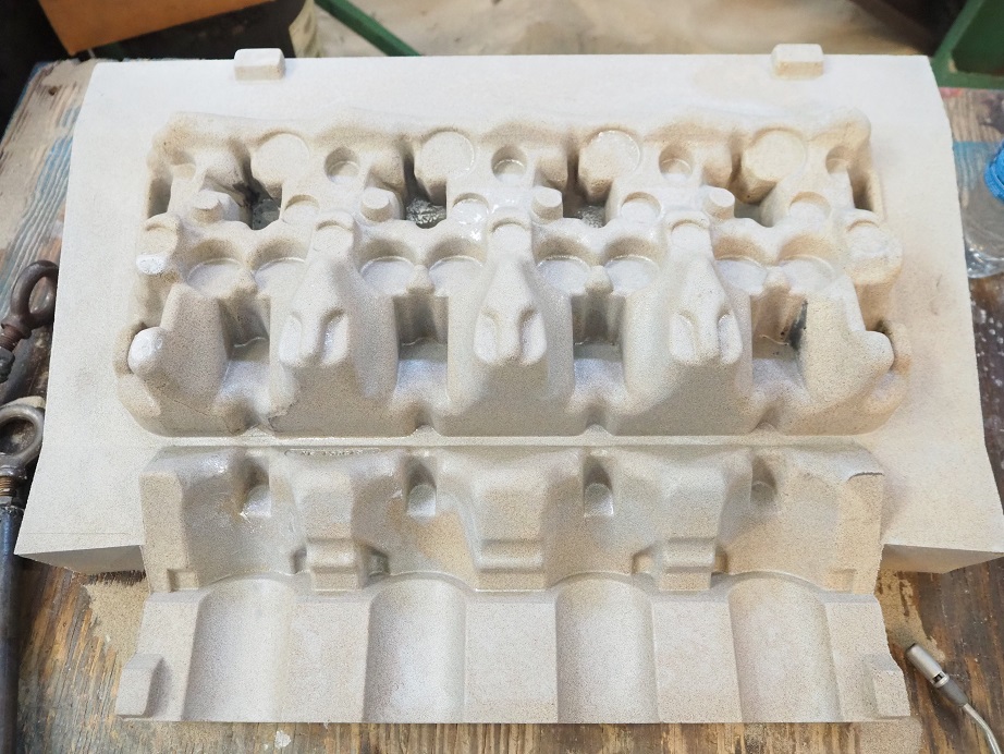
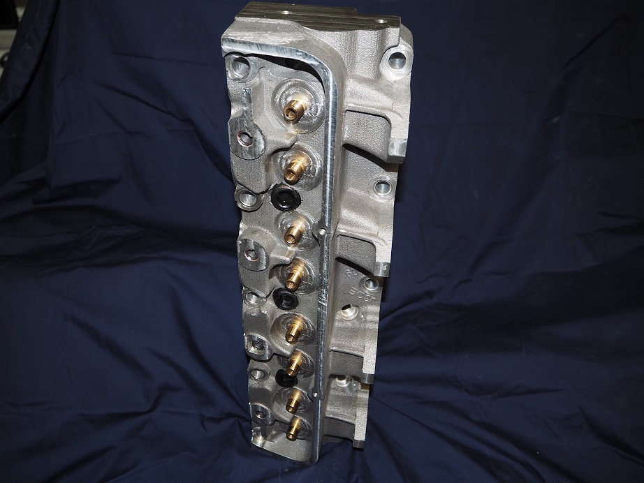
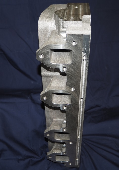
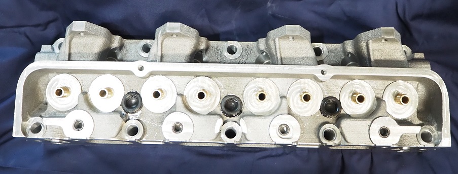
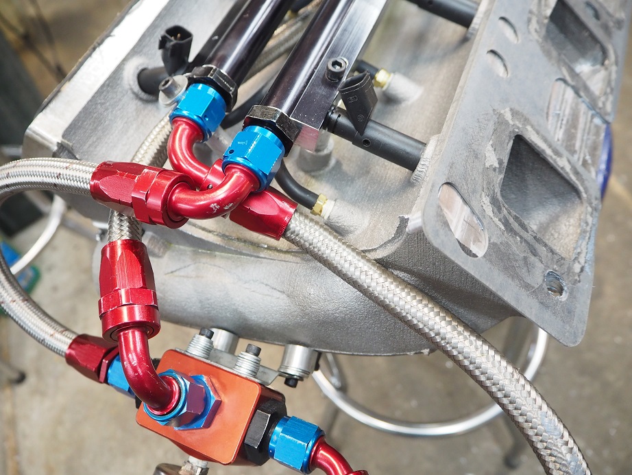
The IR crossram intake was the most complex intake to get up and running on the dyno.  This one was cast originally as eight individual runner castings, to bolt onto the intake adapter.  However, this arrangement made it nearly impossible to get the fuel injectors, fuel rails, and vacuum taps (which are all under the intake) installed with it assembled on the intake adapter.  After fighting with that for several days I finally concluded that I needed to redesign the intake as a single piece, which would be flipped over for installation of the fuel and vacuum system, and then installed on the intake adapter. 

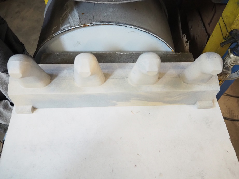
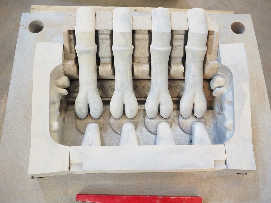
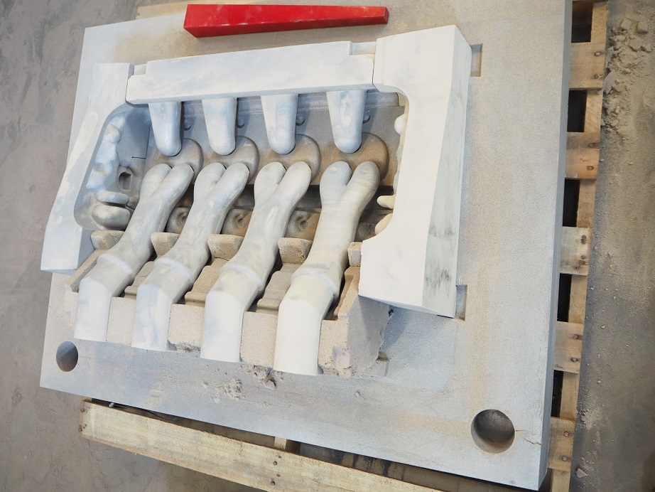
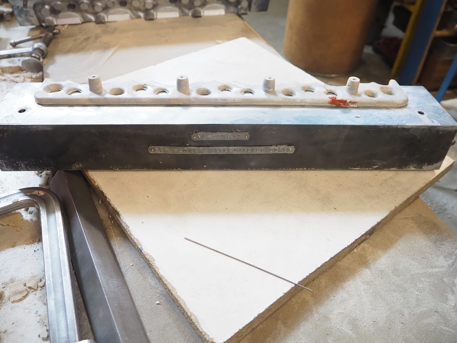
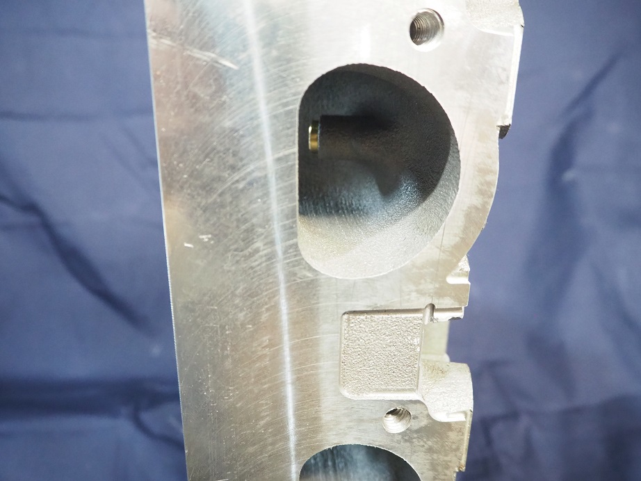
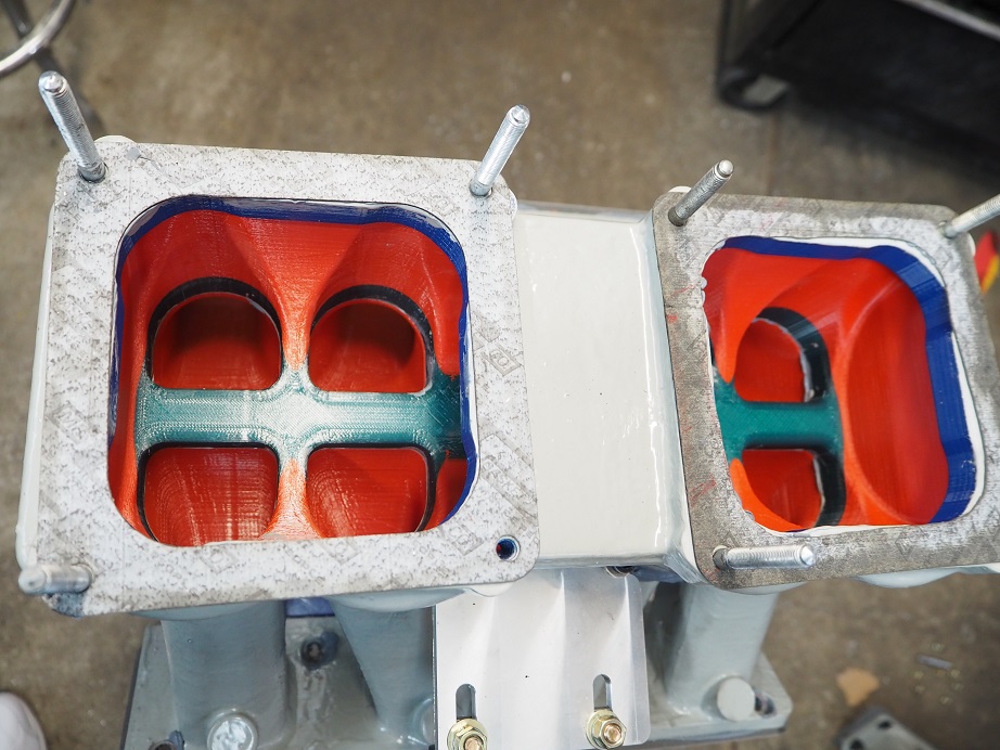
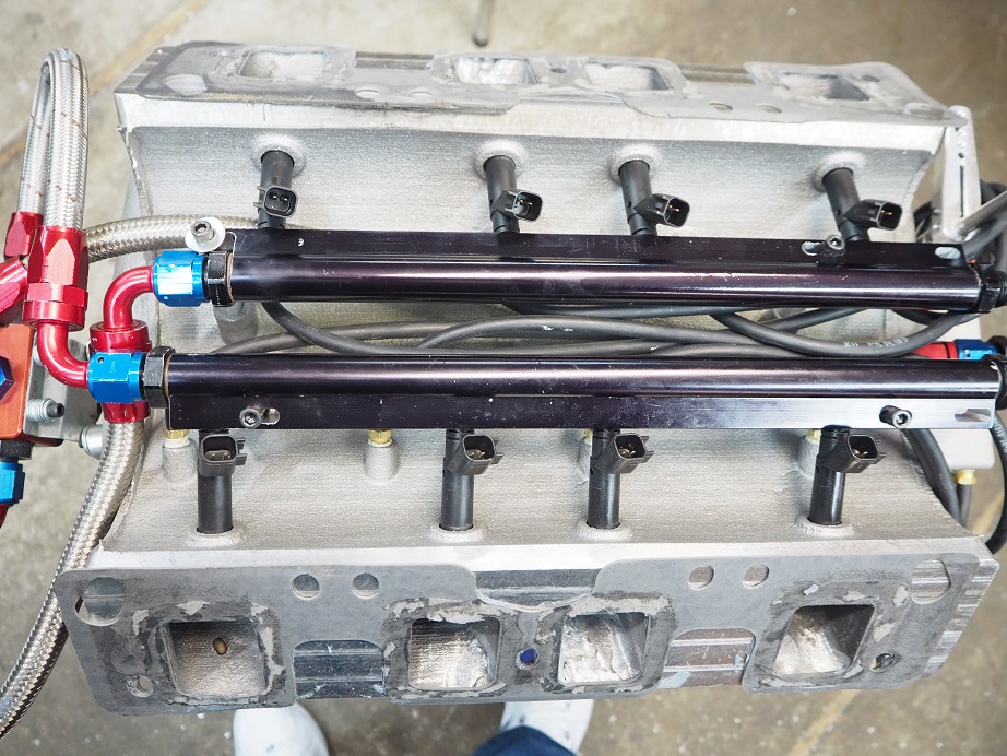
After redesigning the casting and getting it cast, of course I had to completely rewrite the CNC code to machine the intake.  I also needed a new machining fixture.  After getting all that done, the fuel system and vaccuum system was test assembled under the intake.  The new casting had some bosses on the bottom side of the intake to mount the fuel rails, but one of them turned out to not be in the ideal spot, so that will have to be changed before production tooling is made.  But overall the new setup worked.  The photos below shows how the underside of the intake looks with the fuel and vacuum systems installed:


Next the throttle linkage had to be redesigned to work with the new casting.  The first version did not look robust when it was completed, and it was too high off the top of the intake, so a second version was started from scratch.  This one still has some issues, and it will be tweaked a little before finalizing it for production, but it works well enough to run on the dyno.  The production casting will be changed to add some bosses for attaching a return spring on each bank of the intake, plus an idle screw and an opening stop screw for each bank.  Finally, when it came time to mount the fuel pressure regulator I wanted it up front for easy access, and had neglected to add a boss at the front of the casting for mounting it, so it was just screwed into the front runner.  The production casting will put a boss in that position with a couple of mounting holes, to make it easier and cleaner to mount.

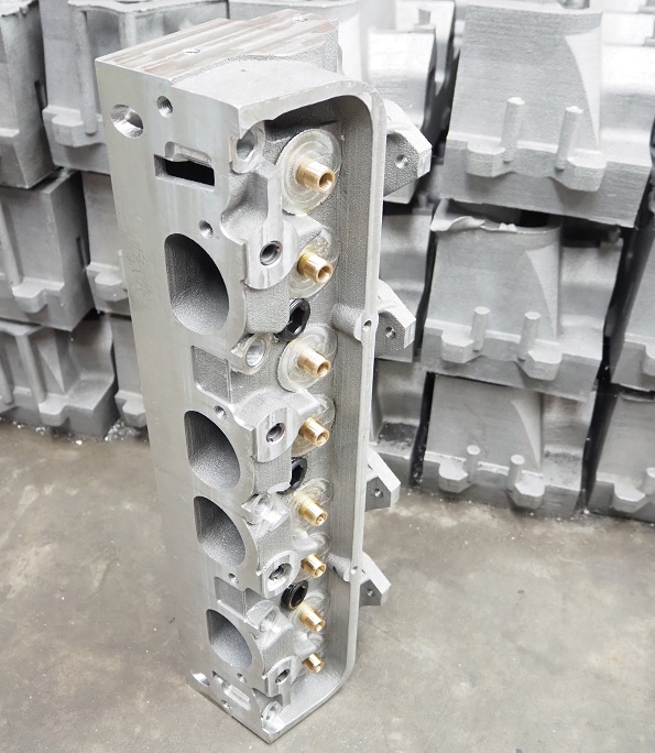
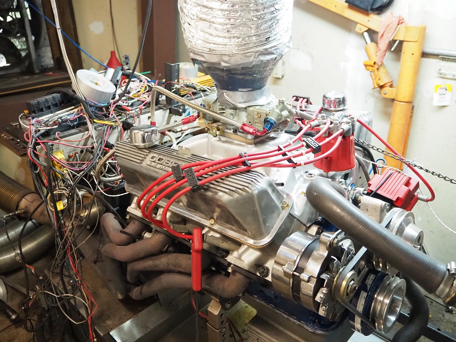
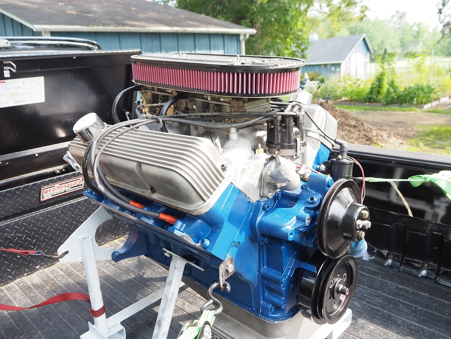
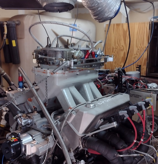
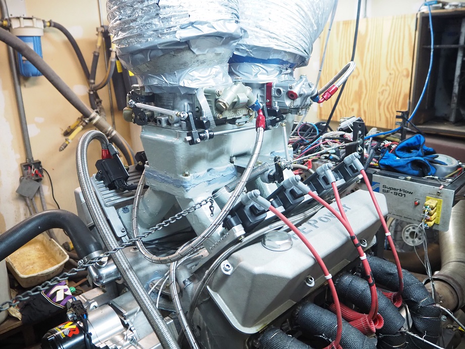
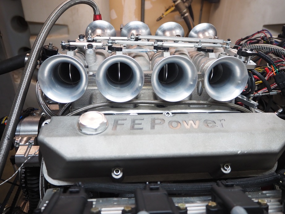
All this took a lot of time to accomplish; the intake probably came apart and went back together six or eight times before it was ready for the dyno.  But finally this week the time arrived.  Here are some pictures of this intake mounted on the engine:


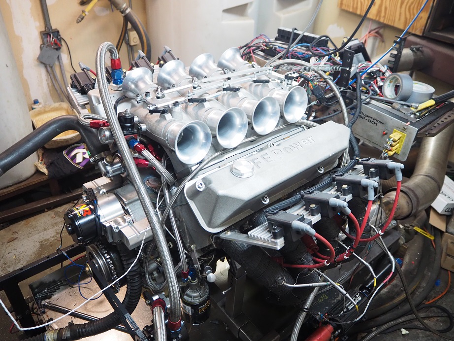
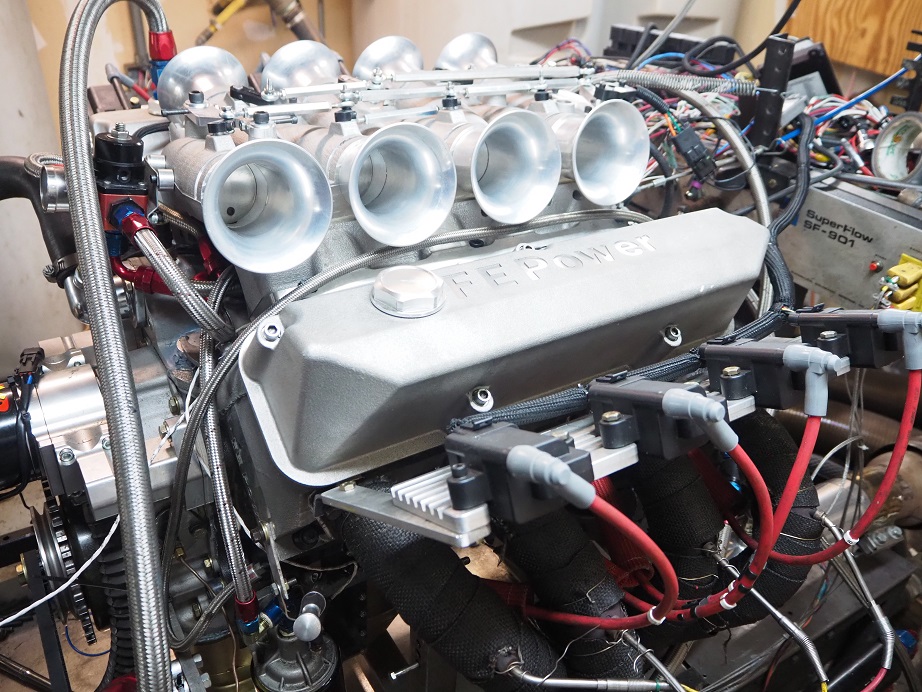
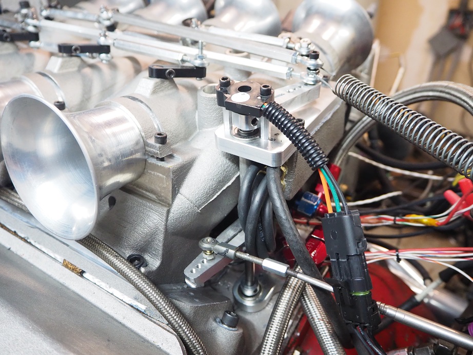
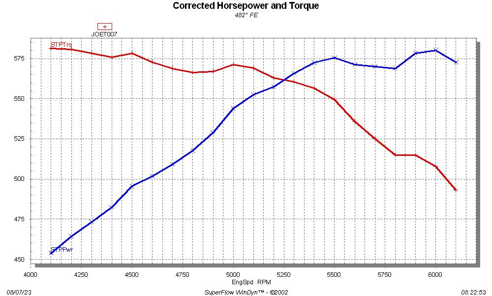
The dyno mule has been using the MS3-Pro EFI system to control the engine's timing, with the crank and cam sensors and no distributor, so it was easy to just add the fuel system from the MS3-Pro to run the injectors.  This setup is low compared to all the other intakes, and uses long runners, so it was expected to make a lot of low and midrange torque, but not as much top end horsepower as some of the other intakes.  Also, as an individual runner intake, it was going to be peaky (In fact the power and torque curves from this intake look very similar to the Hilborn setup I ran on my SOHC years ago).  But it started right up on the dyno, with only real issues being getting the throttle linkage adjusted correctly.  This intake idles with the butterflies almost completely closed; if they are cracked open even a little, like maybe .040", the engine is right up at 2500 RPM.  Hilborn used to recommend setting the idle so that a strip of newspaper would barely slide out of the gap between the throttle bore and the throttle plate, and that is probably just about right for this setup.

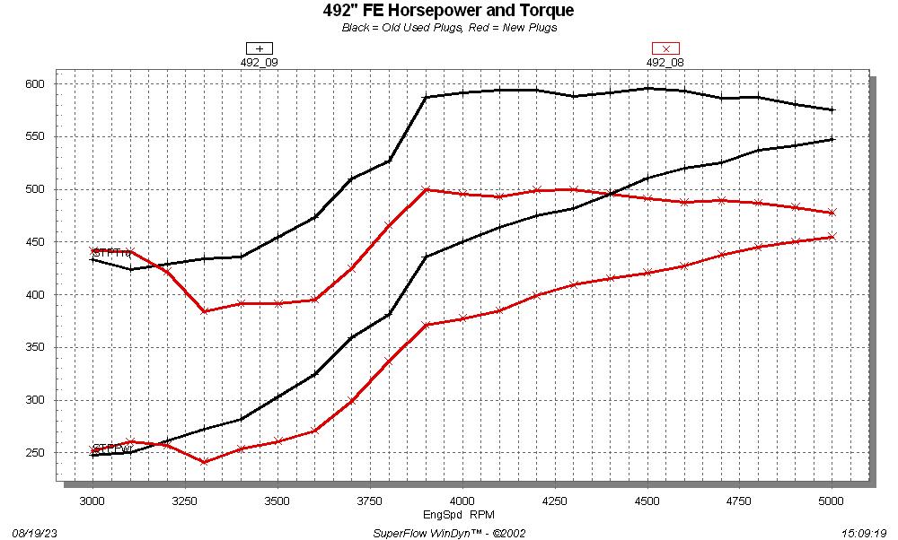
The dyno curves for the tunnel ram and the IR intake are shown below.  The peaky nature of the IR intake is evident, especially below 4500 RPM.  But it is making huge torque down there, almost 600 foot pounds at 3000 RPM and nearly 700 foot pounds at 3800.  During the dyno pull, as the peak at 3800 approached, the sound from the engine was unbelievable!  You could really tell the power was increasing.  The IR intake actually made the most torque of any of the intakes, edging the tunnel ram at 767 foot pounds.  As expected it flattened out after about 5500 RPM, but to my surprise it started gaining again at the higher engine speeds, and actually surpassed the tunnel ram's power at 7000 RPM.  It looks like it's headed for another peak at a higher engine speed.

In contrast the tunnel ram made smooth power up to peak in the 6300-6500 RPM range.  It made a remarkable 763 foot pounds of torque, and 865 HP, before it started falling off.  The manifold behaved nicely on the dyno, no special tuning or adjustments necessary.  It would be a great bracket race manifold, for someone who wants to lauch at 5000 RPM and shift at 6500-7000, to go through the lights at 7000+.


So, FINALLY after a year and a half of concerted effort, I'm ready to go to production tooling with these intakes.  I will be sending out a summary to my customers and asking for their input on which intake manifolds they may be interested in.  If there is little or no interest in one of them, I will probably just produce five instead of all six.  We'll see what everybody says.  I'm currently building a 390 stroker engine that will use a set of my SE heads, and I will be putting the IR intake on that engine.  I may go to the low 4V intake for my Mach 1, so that I can put the original hood and shaker scoop back on it.  And I want to use that tunnel ram on something, just not sure what yet...


15
Vendor Classifieds / FE Power #13001 Intake Adapters
« on: March 01, 2022, 10:42:08 AM »
I currently have three  two one of these intake adapters available.  This is a blem intake with quality thread inserts (not Helicoils) in six of the 351C bolt holes, for $539.

The next production batch of these that I get will have a big price increase, because of a price increase on the raw casting from the foundry.  Right now I'm guessing they will go up to around $650.  If you want one, now is the time.  Leave me a message here, email me at jayb@fepower.net, or call at 952-428-9035.  Thanks!

Pages: [1] 2 3 ... 25