Show Posts

This section allows you to view all posts made by this member. Note that you can only see posts made in areas you currently have access to.


Messages - jayb

Pages: 1 ... 493 494 [495] 496
7411
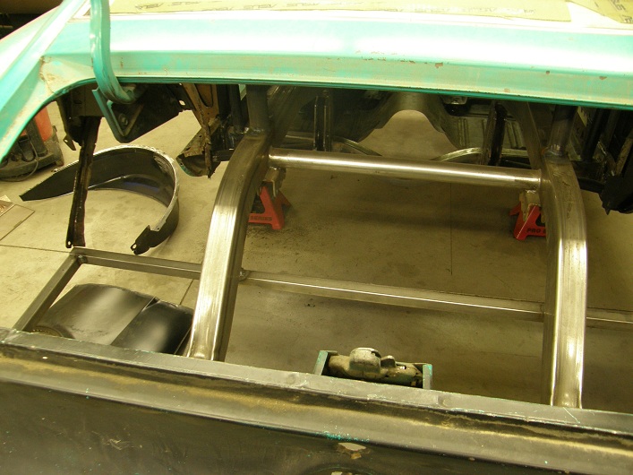
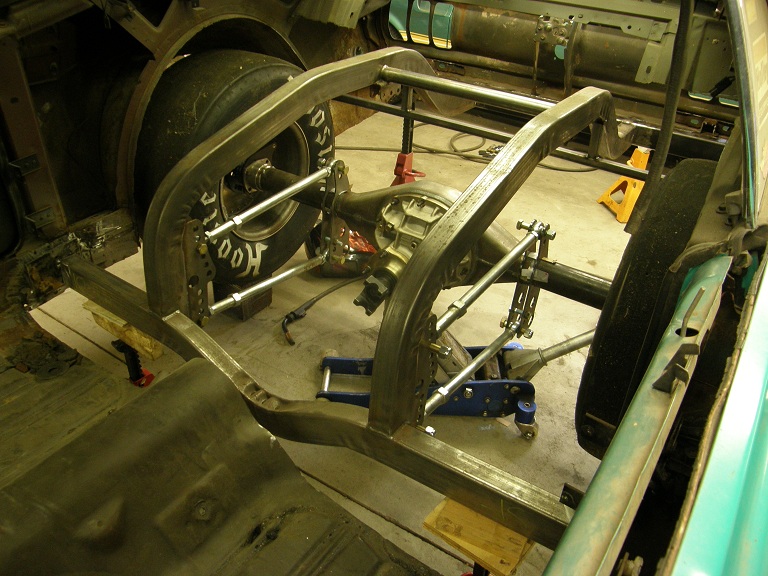
Once again I made a lot of progress on the car this weekend, but once again I also fell a little short of my goals for the week. I did make it out to the shop on a couple of weekday evenings this week, and made some progress on the work under the car. The first thing I did was bend up a subframe connector out of roll cage tubing for the driver's side. After a couple of hours bending, fitting, and notching, I had the tube shown in the photo below:


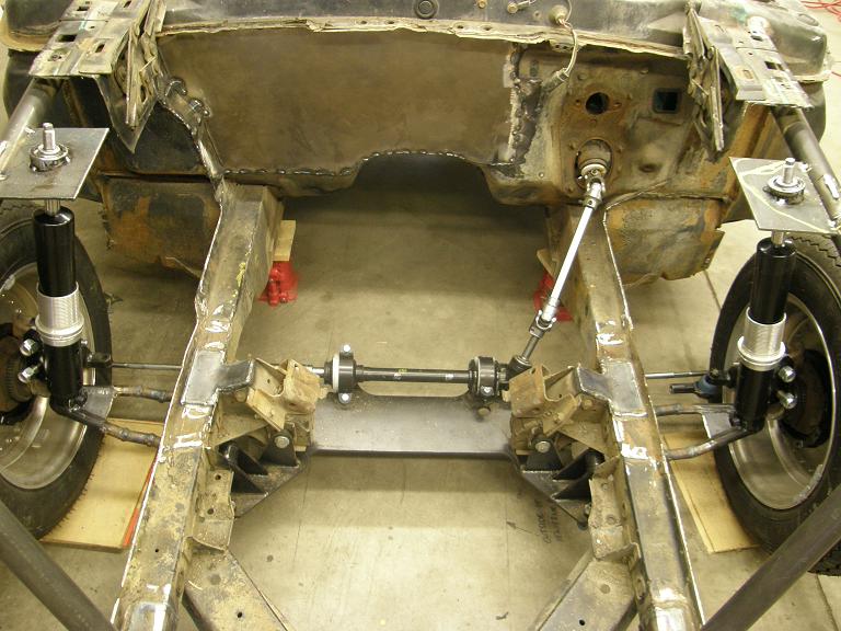
The small tube coming off perpendicular to the long one was welded on after the photo was taken and also connects into the front subframe, to give some leverage to the bar. I planned to attach the bars to the front subframe by first welding some 1/8" plate to the side of the front subframe rail, and then welding the tube onto the plate, to spread the load. At the back the bar would tie directly into the 2X3 crossmember of the back half kit.

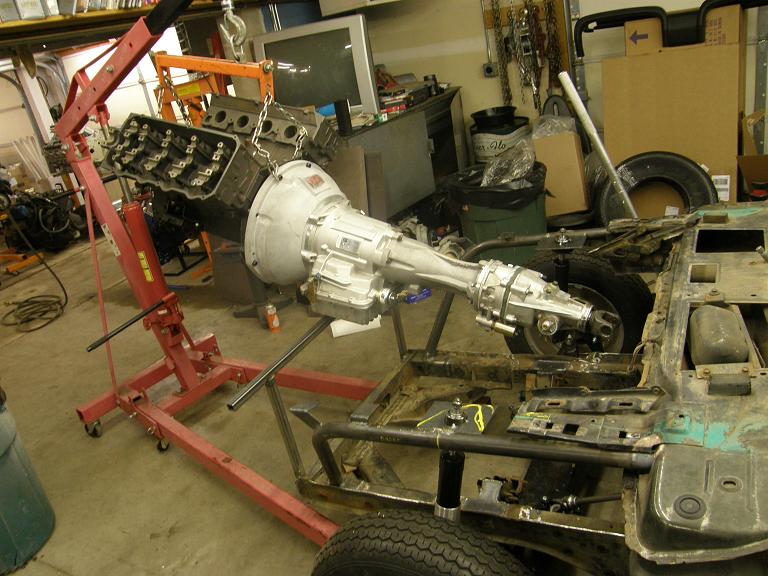
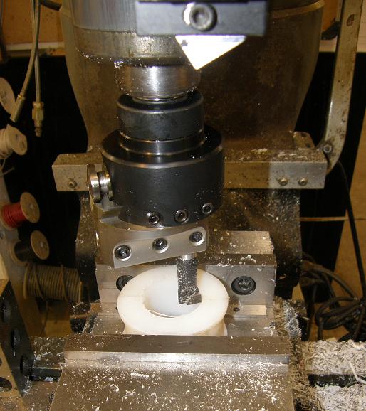
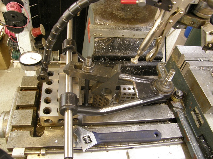
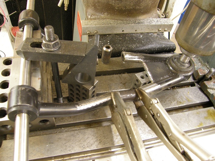
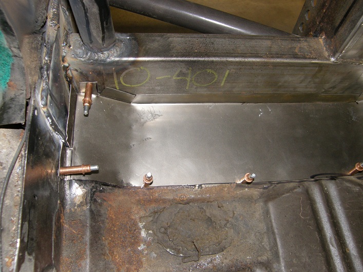
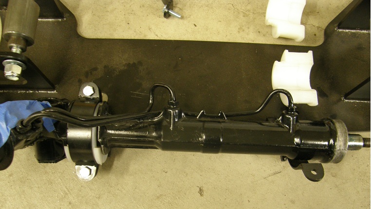
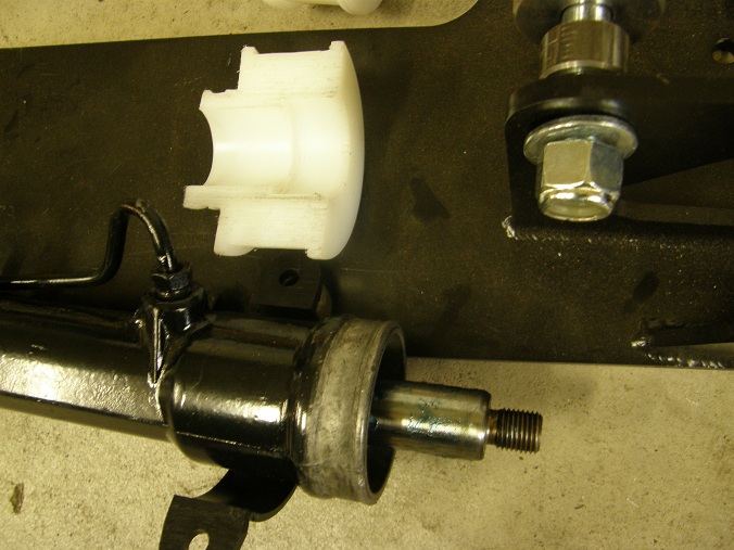
The next free night I worked on the transmission mount. I was getting tired of working around the floor jack that was holding the back of the transmission and the GVOD up, so rather than work on the passenger side subframe I spent some time figuring out how to make the trans mount work. I wanted to use the factory support welded into the unit body of the car that was used with the stock transmission mount, and it seemed like the best way to do this was to build a new mount out of 1" square steel tubing. The back half of the mount was pretty easy, just a straight piece of tubing with a little angle up on one end, but the front half had to dip down to clear the trans brake solenoid, complicating the design. Eventually I got it pieced together, with the back and front tubes welded together with a plate that I slotted some holes in on my mill, to allow some flexibility in position of the transmission. A photo of the partially completed mount is shown below:


After some more welding and some grinding, the mount was ready to install. It seemed to fit fine, and allowed me to pull the floor jack out for better access.

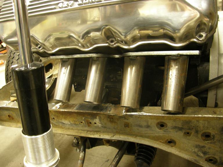
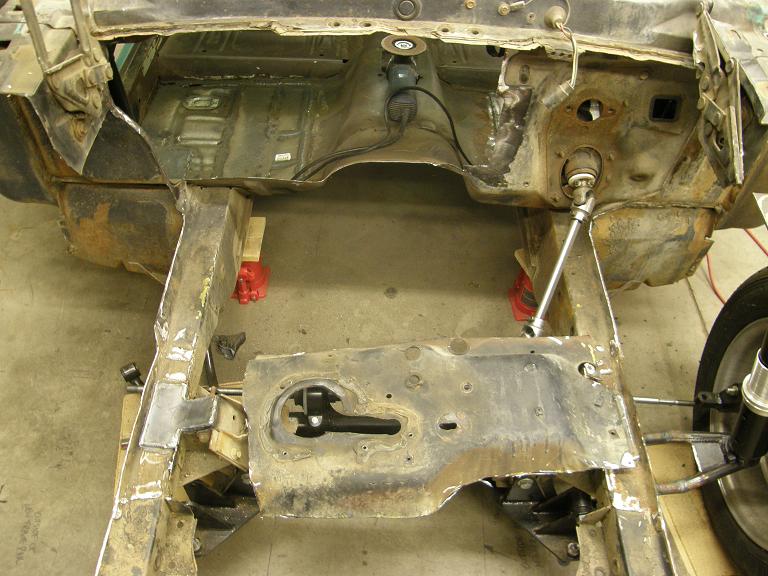
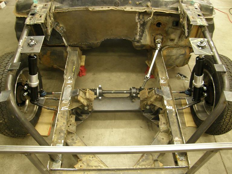
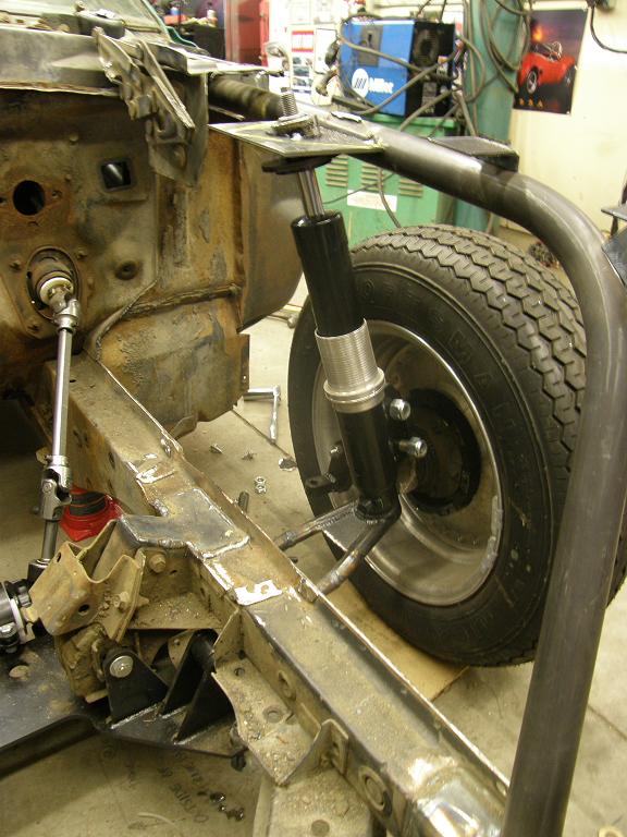
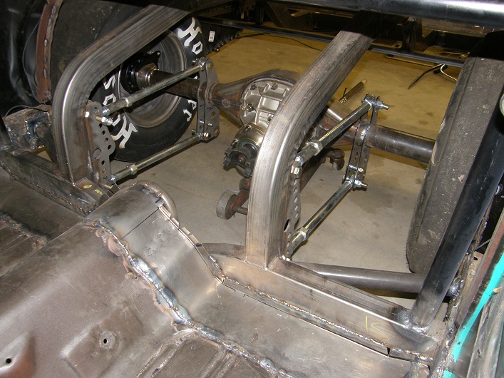
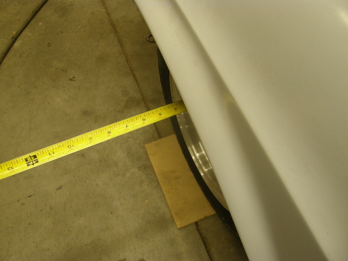
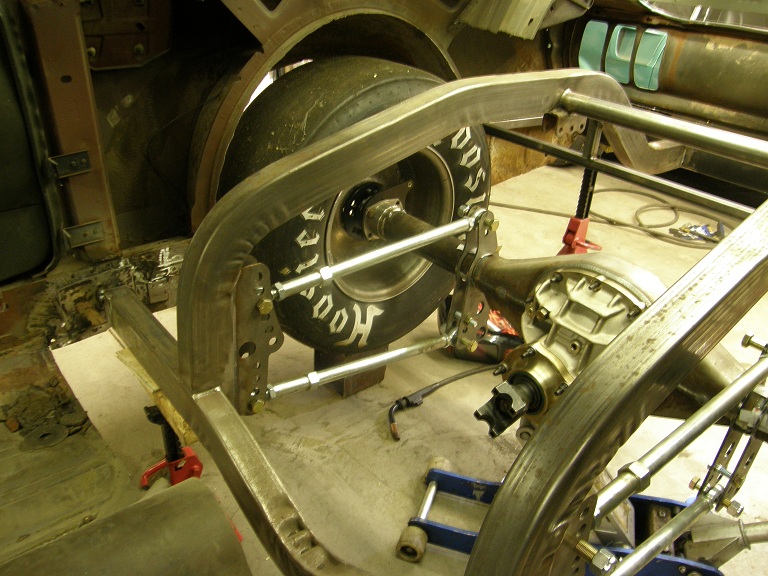
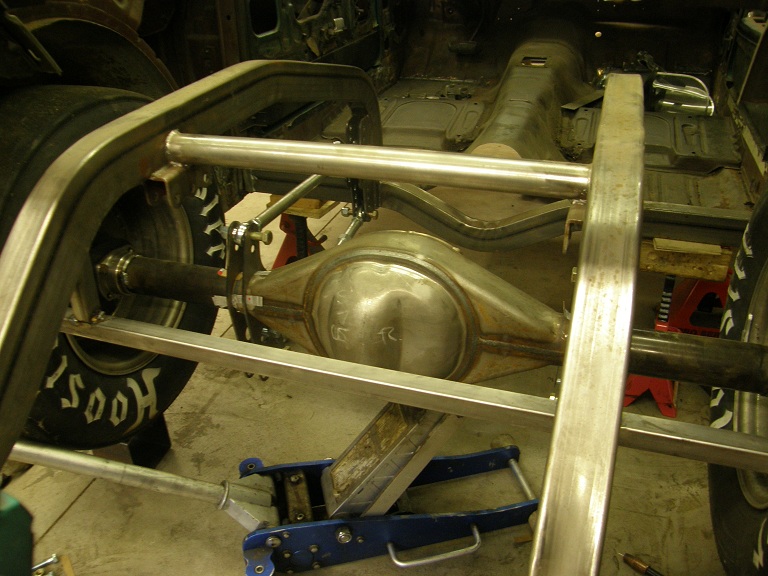
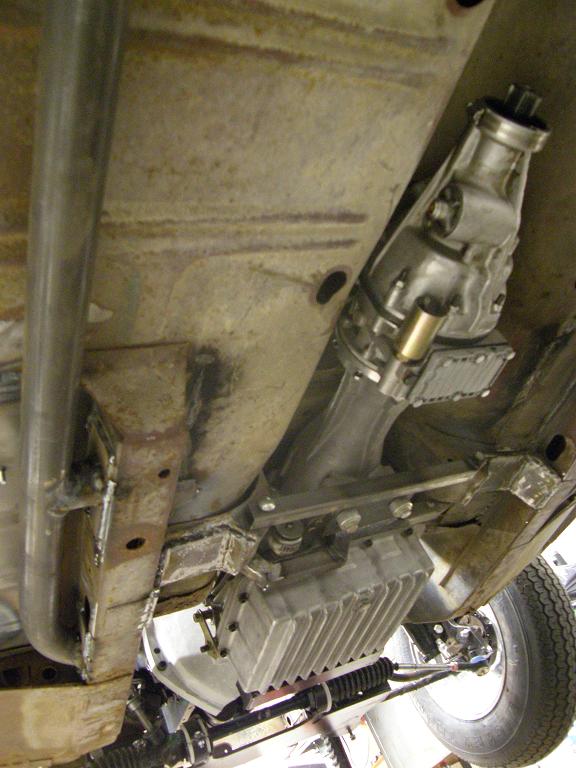
Saturday morning I got back onto the project by bending up the passenger side subframe connector, and spent the rest of the day grinding, fitting, and welding until the subframe connectors were installed. I also notched the original factory support for the transmission mount to allow the header collectors to sneak through this area, improving the ground clearance situation. Here's a photo under the car, showing the front half of the subframe installation and the trans mount and notch in the trans mount support:


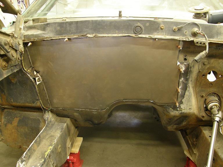
At the end of the day Saturday, after finishing all this stuff, I started thinking about what to do next. One of the bigger challenges left was to get the Wilwood brake pedal and master cylinders mounted, so I spent some time planning out how I would proceed on that in the morning. The Wilwood brake pedal mounts two separate master cylinders that extend into the engine compartment, but they are shorter than the stock master cylinder, so they wouldn't interfere with the big SOHC engine. The master cylinders mount to the firewall facing bracket of the pedal, but the pedal bracket itself is supposed to mount from the top, to some kind of a frame member.

When I had replaced the section of the firewall with a flat steel sheet, I had automatically been put under an NHRA rule which says that if you remove more than one square foot of the firewall, you have to run a crossbar between the front uprights for support. This crossbar can be 1.25" diameter .058" wall chrome moly, so I had ordered some of that tubing earlier from S&W race cars. I decided that I would use the crossbar as a forward support bracket to mount the pedal assembly. I figured I could run some square steel tubing between the crossbar and firewall, and mount the pedal assembly from that.

Sunday morning I was out to the shop by 9:00, hoping to make some good progress before noon, when I had some family commitments. I opened the door to the shop and the first thing I noticed was a whiff of propane in the air. Ruh-roh. I walked out of the shop without turning anything on, and went out and looked at the gauge on the propane tank. It was almost completely empty, showing only about 3% on the gauge. This explained the smell; when the level in the tank goes down that far the pressure in the lines drop, and one of my heaters has a hard time lighting. It will flip on and try to light for 20 seconds or so, then automatically shuts off to prevent a major leak of propane into the building. While it is trying to light, propane is coming out of the gas line, resulting in the smell. It will repeat this process every 15 minutes or so, and results in a faint propane odor in the shop.

I shut the valve off on the tank, carefully opened one of the overhead doors in the shop to air it out, and considered the necessity of working in the shop with no heat. I didn't want to just keep the other heaters on until the propane ran out, because the gas company needs to do a leak check on the building if the tank is completely empty. I decided that despite the lack of heat, I could tolerate working in it for a while, so I started back in on the car by 9:30. The thermometer in the shop read about 38 degrees, which wasn't too bad.

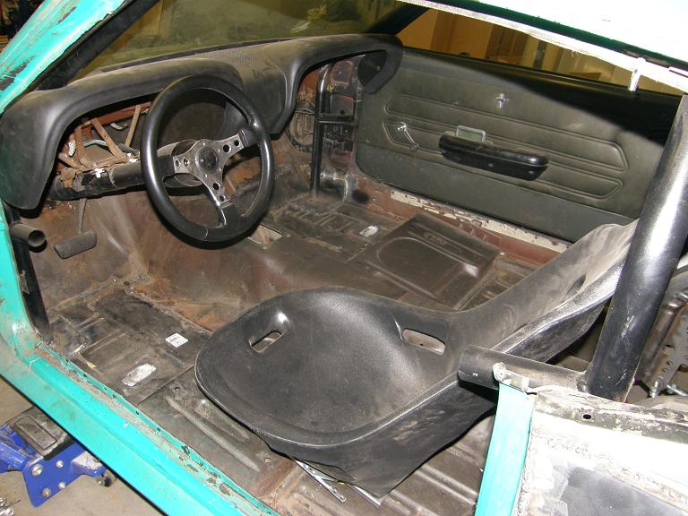
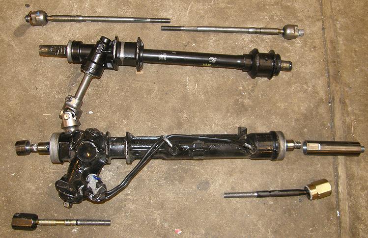
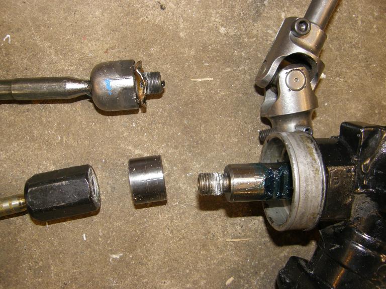
First thing I had to do was remove the factory brake pedal and pedal tree. Of course, this piece also functions to hold the steering column in position, so before removing the tree I had to fabricate an X-shaped wood support to hold the steering column in position. Later I planned to machine a U-shaped bracket to bolt to the crossbar, which would position the steering column. After the wood support was installed, I removed the factory brake pedal and pedal tree.

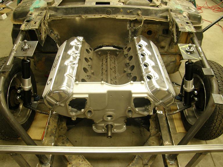
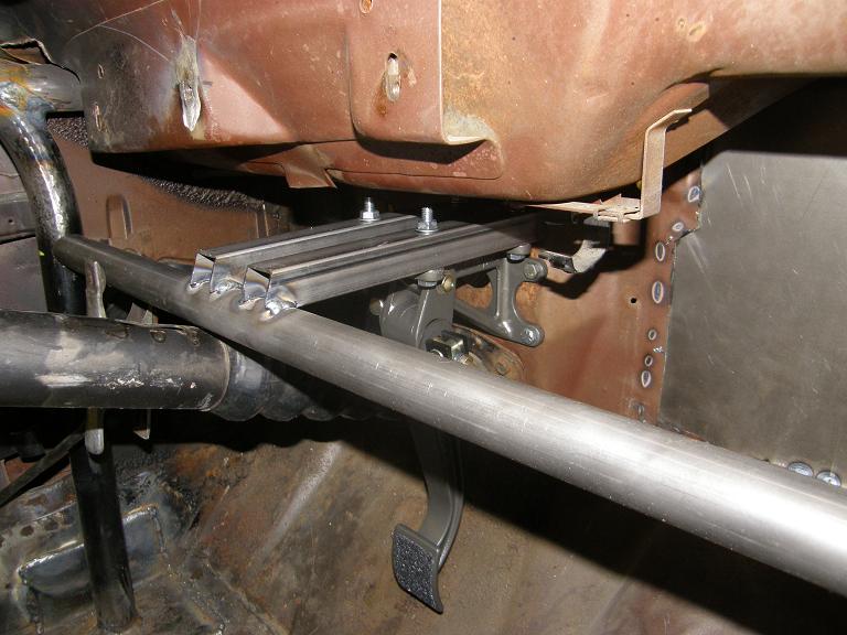
I cut the 1.25" diameter chrome moly crossbar carefully and notched the ends a little at a time, so that when it was finished I had a nice snug fit between the front cage uprights. Next I figured out where I wanted the pedal, and mounted it without the master cylinders, but using the master cylinder bolt holes so I could position it where I wanted against the firewall, and temporarily bolt it into position through the firewall. Then I made up a mounting frame that the top of the pedal assembly would go to, from 1" square steel tubing, that would weld to the crossmember and extend to the firewall, where it would bolt in place through a support plate I would weld to the outside of the firewall. By noon I had the basic arrangement frame up, as shown in the photo below:


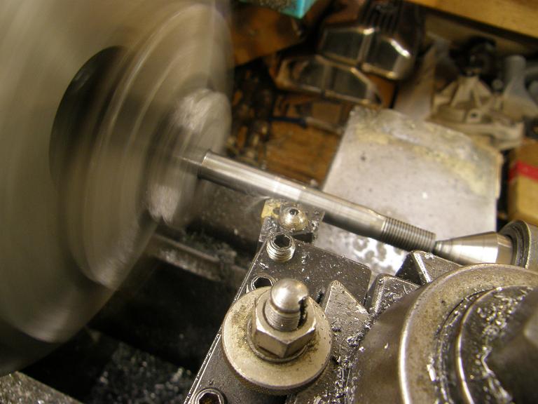
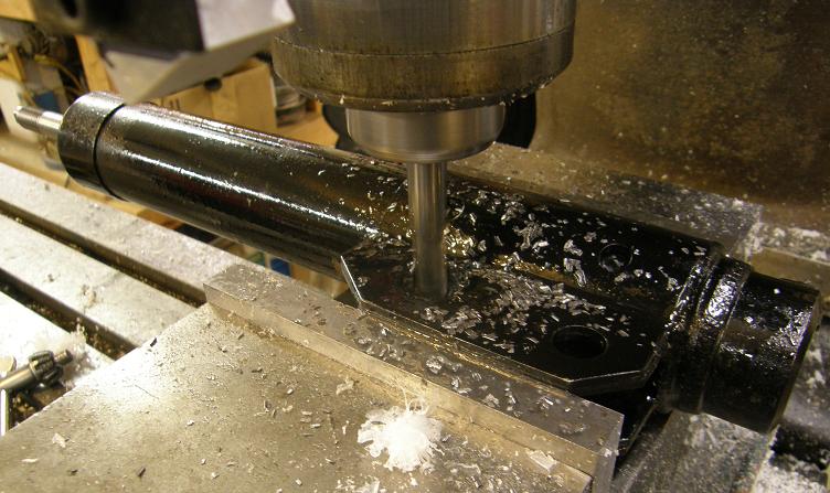
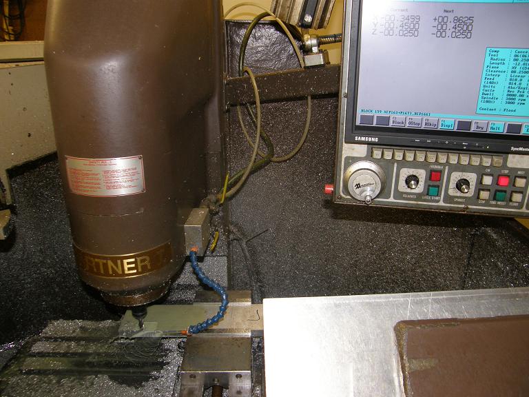
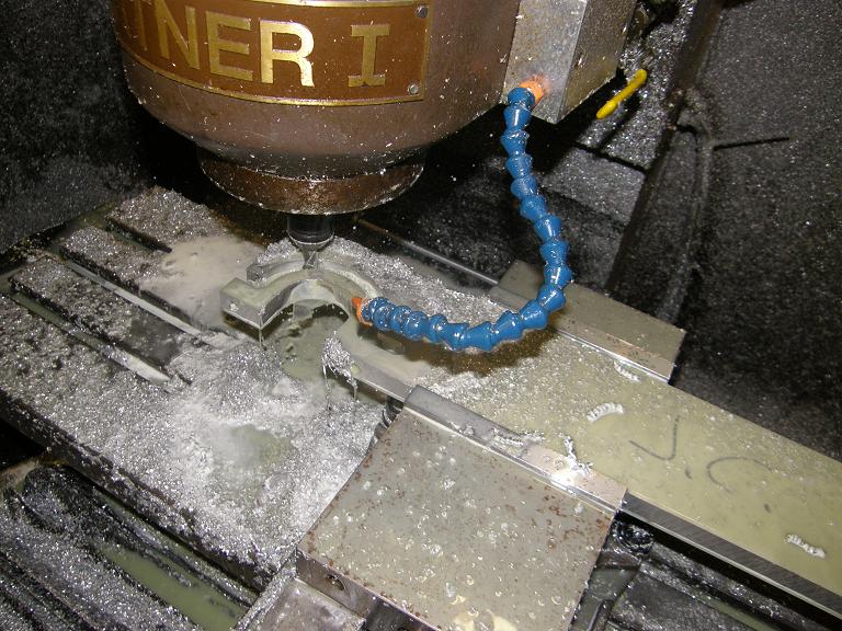
Later in the afternoon after returning from my family commitment, I decided that I'd better get to work on the U-shaped bracket that would hold the steering column to the crossbar. I decided to make this on my CNC machine, because it would be faster than doing it manually on the Bridgeport. I drew up a rudimentary sketch of what I wanted on my whiteboard, selected a piece of 3/4" thick aluminum plate that I had in my materials pile, and spent about a half hour programming the machine to make the part. Once it started up I was able to keep working on some other projects while the part was being made. Here's a couple of pictures of the CNC machine working on the part:


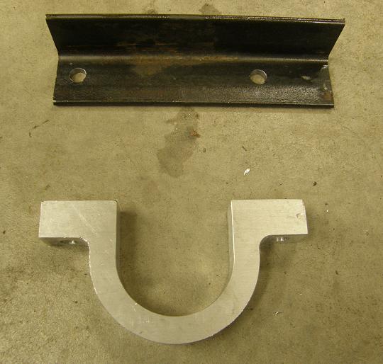
One of the things I did while the machine was running was to decide how I would bolt the U-bracket to the cross bar. I decided to take the low tech route on this, and cut a piece of 1 1/2" angle iron, with holes drilled in it at the proper locations to take the bolts from the U-bracket. The angle iron would just weld to the crossbar, and the bracket would bolt to that. Here's a photo of the finished aluminum U-bracket and the angle iron piece:


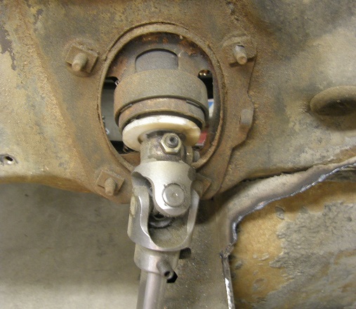
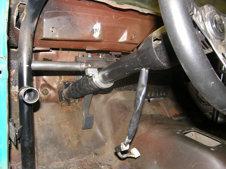
Before going in the house tonight to help the kids with their homework for Monday, I bolted the bracket to the piece of angle iron, and positioned it up against the crossbar. After double checking the steering column position to make sure it was correct, I tack welded the angle iron bracket to the crossbar. Finally, I removed the wood support on the steering column, and snapped the following photo:


I still haven't welded in the crossbar yet, so now that everything is tacked in place I will remove the brake pedal assembly, disconnect the U-bracket, and pull the crossbar out of the car, where I can finish welding everything solidly in place, and add some support gussets and brackets to the brake pedal mount. Then, I can reinstall the crossbar and weld it in after it is positioned correctly.

I was hoping to get the Lokar gas pedal installed today, along with the supports for the seats so that I could bolt them into position, but I ran out of time for that. Besides, it was getting cold out there! I will have to call the propane company for a fill tomorrow. With luck I can get the gas pedal and seat supports done during the week this week, and my driveshaft will hopefully arrive from Mark Williams, so that I can finally tackle the rear end welding next weekend, in addition to finishing up the front crossbar and brake pedal / master cylinder installation. Then, the week after I can start the headers, and the chassis work will be getting close to completion. I will post another report next weekend.


7412
This week was another fairly productive week on the new car, although I didn't get done as much as I wanted to. I had been planning to get the driveshaft angles set and get the rear end components mounted and tacked into place this weekend, but on Monday when I ordered the driveshaft I decided that I'd rather have the driveshaft on hand and installed before I finalized the rear end configuration. So, instead I decided to move ahead with finishing up the chassis work at the front of the car, and then look at getting some tubing installed to tie the subframes together.

It turned out that the work on the front of the car took longer than I thought. One of the things I wanted to do at the front was to drop a tube down from the front roll cage extension tube to the factory frame rail, in order to support the frame where the front suspension load would be. As I was looking at this on Friday night, it became clear that the header pipes had to come straight through this area, and if I didn't put the tube in the correct spot it would interfere with the headers. So, before I could even start thinking about positioning the tube I had to know where the header pipes would be.

As a result, I spent Friday night and early Saturday morning fabbing up the first several inches of primary pipes and the header flange for each side. I was hoping to have at least six inches of straight pipe coming out of the head ports before turning the pipes towards the back of the car, but it appeared that this might be optimistic, based on the location of the exhaust ports and the stock frame rail. No way to tell for sure without actually mocking it up, though. On the heads I'm using the ports exit the casting at a 15 degree angle, so the pipes have to be welded onto the header flanges at this angle to keep the exhaust coming out of the port in a straight line. I dug out some 2 1/8" exhaust pipe for this task, because I was planning on using 2 1/8" to 2 1/4" to 2 3/8" stepped headers, just like what I had previously used for my Galaxie. This would allow me to re-use the collectors from those headers; since this car is getting the 585" SOHC from the Galaxie, I'm going to put my 510" engine back in the Gal, and I have a different set of headers for that engine.

On the topic of the Galaxie, I got an interesting call from my friend Joel this week (aka Captain Stabbin', also aka the Trunk Monkey). Joel suggested that I get the Galaxie ready for Drag Week in 2011 also. He offered to donate an 800 HP capable manual transmission and clutch setup so that the Galaxie would be a stick car, and he could drive the Galaxie this year, while I drove the Shelby clone. That's a pretty interesting idea that I'm still considering; it would be fun to have two cammer cars at Drag Week! Of course, I have a perfectly good C-4 and driveline for the Galaxie, and the car was already set up for that, so I wondered why Joel wanted to swap in the manual. He responded that he really didn't want to drive a car with "that oily, greasy, smelly fluid coupling behind the engine" LOL! But I'm not sure I'd want to run somebody else's transmission in the car, to say nothing of having two cars in the same class, and the extra expense of fielding two cars at Drag Week. I'm still thinking about this; no decision is required right away, and we will see how things play out this year. But it sure would be fun to have both cars at the event.

Back at the header flanges, I cut some 6" sections of the 2 1/8" tubing, cut off at a 15 degree angle, and welded the tubes into my header flanges. After getting done with this on Saturday morning, I installed one of the flanges on the driver's side to see how it would fit. Unfortunately, as I had expected, the six inch head pipes were not going to fit; at the back the flange wouldn't even bolt into place on the engine. Here's a photo:


It looked like if I cut the pipes down to 5" the flange might at least bolt onto the engine, and give me an idea of where the pipes came past the frame rail. Also from this mock up it appeared that the spot weld flange at the edge of the frame rail was going to be in the way of the primary pipes. As result I decided to cut this flange off the frame rail, and weld up the seam. After getting this done I cut an inch off all the driver's side primary pipes and was able to get the header flange mounted on the engine.


Sorry for the poor photo quality. With the pipes on the engine, I was able to determine where I had to put frame tube so that it would not interfere with the header pipes. I also took a mandrel bent section of 2 1/8" exhaust pipe and using this as a gauge, determined where I would have to cut the primary pipes off in order to get them past the frame rails. It looked like the straight section of pipe would be anywhere from 3 1/2" to 4" depending on the pipe's location. Not as long as I was hoping, but at least livable, and certainly a lot longer than the pipes would have been had I opted to go with a Boss 429 style engine compartment.

Shortly after this a couple friends of mine stopped over to ask some SOHC questions; one of them is in the business, and has a customer who would like to put an SOHC in a Cobra replica, so he wanted to take some measurements off one of the engines I have on an engine stand to see what kind of fitment issues he would be dealing with. While talking we were looking at the front end of my Shelby clone, and they suggested that I use some of the 1 1/4" chrome moly tubing I had on hand to triangulate the front roll cage extension. They suggested going from the junction welded at the front of the stock frame rail, up to the upper strut mount, and then back down to the stock frame rail at the firewall. I could still run my bar from the middle of the front roll cage extension down to the stock frame rail to support the suspension mounting point and engine mount area, but the other bars would triangulate the whole setup.

I really liked this idea. After my friends left I started working on this, but quickly came to the realization that this triangulation bar would cause a couple problems. One would be that it would limit my ability to remove the engine's valve covers, especially if I used studs to mount them. The second, and more serious issue was that by putting in a bar that ran down to the stock frame rail at the firewall, I would seriously limit the room for the headers to go through this area. The room on the driver's side was already limited by the steering linkage, and I figured I could only fit a couple of the header tubes through there as it was. Installing the bar meant that at least three of the tubes, and maybe all four, would have to wrap underneath the stock frame rail. This would lead to ground clearance issues that I didn't want to contend with, so after kicking it around a little I went back to my original plan, which was the bar down to the stock frame rail, a short support bar up to the upper strut mount, and a triangulation bar at the front of the roll cage extension tube, similar to what I'd seen on certain aftermarket roll cage kits.

By the end of the night Saturday I had the bars cut and tacked in on the driver's side. Sunday I spent most of the day on the equivalent passenger side tasks. Here's a couple of photos of the front of the car with these modifications:


I also got my new front wheels this week, and had the front tires mounted; Sunday afternoon I swapped them onto the car. Here's a photo:


I think those wheels look pretty good. I was really waffling between these Centerlines and Weld Wheels, and I liked the Weld's because they look good too and are probably a little lighter. However, the Welds were double the price of the Centerlines, and they are also not available in a 5 inch or 6 inch width. I didn't want to go with a really narrow rim in the front, because I don't like the way the cars handle with the 3 1/2" wide wheels, plus I've had some bad experiences with road hazards and the narrow wheels (pothole + 3 1/2" wheel = blown tire and bent rim). I've also seen this at Drag Week, in 2005 when one of the guys in my class hit a pothole and blew a tire. So I settled on the Centerlines because they were available in a 5" rim width.

Next I spent some time trial-installing the front seat in the interior, because I wanted to determine how I was going to mount it. I was thinking about installing the subframe connection bars so that they came through the floor behind the front seats, but I didn't want to do this without knowing first where the seats would be installed, in case there was some interference there. After I got the driver's side seat installed, I finally got a chance to sit in my new car. The seating position was good, and mounting the seat farther back from stock gave me plenty of leg room, which is sometimes a problem in early Mustangs. Here's a picture of the admittedly incomplete interior:


Finally, the last hour out in the shop today I spent the time laying under the car, and figuring out where I was going to run the tubes to connect the subframes, and also how I was going to make up the transmission mount. Based on the seat position I figured I'd be better off running the tubes completely under the car until I got right up to the rear subframe, and then just notch the floor a little and bend the pipe to come through and weld to the back half crossmember. I also figured out that I could notch the factory unit body crossmember that the transmission mount attaches to so that the header collector could come through up near the floor of the car, for maximum ground clearance, and then reinforce the notch to maintain the required strength for the mount.

At the beginning of the week I had been hoping that I would be able to get the subframe connections and transmission mount completed this weekend, in addition to the front end work, but obviously this will have to wait for next weekend. It is pretty obvious at this point that there is no way I'll be done with the chassis work by the end of this month as I was originally hoping, and with certain family commitments in March, it is probably realistic to assume that the chassis work won't be completed until the end of March. Hopefully this will still leave me enough time to get the car painted by mid-May, and on the road by the beginning of July. We will see...


7413
This week was a fairly productive one on the new car project. Last week I had gotten stalled on finishing up the steering installation due to different thread size on the manual rack as compared to the power rack, and the requirement to make a rack extension incorporating these threads. On Wednesday I received the tap and die for the 16mm X 1.0mm thread size I'd ordered from McMaster Carr, and also the 4130 chrome moly steel to make the extension. Wednesday night I snuck out to the shop rather late and got the 16mm bar threaded up about an inch, which was going to be needed for the extension. Thursday night I had a little free time after the kids went to bed, so I thought I would drill the 1 1/4" bar with the 15mm drill bit I had purchased. Unfortunately I ran into a problem with this, because the drill bit wasn't necked down at all to fit into the chuck, and the chuck for the tailstock of my lathe would only go up to 1/2" (about 12.7mm).

I thought about drilling the hole 9/16" and then boring it the rest of the way to 15mm (0.590"), but my small boring bar isnt' that stable, and I had to bore the hole a long way, so I didn't feel that this was a reasonable option. The best option would be to purchase a new chuck for the tailstock that would hold a larger drill bit. Buying new tools is always a double edged sword for me; on one hand, I hated the idea of spending a bunch of money on a new chuck just to drill one hole, but on the other hand, as a confirmed tool junkie, I love getting new tools!

I decided to go ahead and buy a new chuck. I went through the Enco web site and found a cheap chuck with a capacity of 1/8" through 3/4", and also the adapter required to fit the #4 Jacob's taper hole in the back of the chuck and the #3 Morse taper of my lathe's tailstock. Friday morning I called Enco and paid the usual exorbitant fee to get the parts shipped and delivered to me on Saturday; I was really keen on getting the rack extension made and the steering system finished up over the weekend.

Saturday morning my wife and kids were off at a basketball game, so I had some free time in the shop. The new chuck and adapter had not arrived yet, so I decided to tackle a project that I had been putting off. Part of the firewall of a '69 Mustang extends out into the engine compartment farther than the rest of the firewall, and I wanted to cut this piece out and replace it with a flat piece of sheet metal to give me more room behind the engine. I hate sheet metal work, so I decided to tackle this project right away while I was fresh, and hopefully get it finished up fairly quickly. After crawling into the engine compartment and using some straightedges to determine where to cut the firewall, I cut the hole with a circular cut-off wheel in my 4 1/2" grinder. After trimming the hole the engine compartment looked like this:


The piece of the firewall that I removed is shown in the foreground of the photo. I used this piece as a template, and transferred its shape onto a piece of 20 gauge steel sheet. After cutting this out and test fitting it, I trimmed it a little for a better fit and put some bends into it at the edges so it would fit the opening. Then I positioned it over the hole with a few klecos; photo below:


The bent section at the left side of the photo had a bunch of cuts in it where I'd had to bend it, in order to make it go around a corner. After this photo was taken I decided to pull the panel back off again and cut those pieces out completely; later after the panel was tacked in place, I made up a single small piece of sheet metal to fill the hole where the cut pieces were removed. After replacing the panel and reinstalling the klecos to hold it in position I tack welded all the way around the outside of the panel, in small buttons, kind of like I had done with the quarter panel installation. This was a long, tedious job; did I mention I hate sheet metal work? Anyway, when I was taking a break I looked out the window of the shop and there was a suspicious looking box on the front steps of my house. Hmmm, probably my Enco order. I forced myself back to welding for another half hour or so, but then decided I could always finish this later when I was doing the final cleanup and painting of the engine compartment, so I put the welder away and went to get the UPS delivery.

Within five minutes of bringing the box into the shop I had the new chuck installed in the lathe and the 15mm hole drilled in the 1 1/4" bar. That was easy. Next I had to counter bore the hole for a distance of 3/4" or so, so that it would fit over the end of the existing rack and self-align. After that was finished I used my new 16mm X 1.0mm tap to tap the 15mm hole. I started it by holding the tap in the tail stock to make sure that the hole was tapped straight, and tapped it to a distance of about 3/4" using a tap handle. On Wednesday night I had used my 16mm X 1.0mm die to make a threaded rod 1 1/2" long, so once I had the hole tapped I screwed the threaded rod into place with a bunch of red Loctite to hold it solidly in place. I went in the house for lunch while the Loctite dried, and then after lunch came back out and cut the rack extension off to the correct length, and tapped the other end. Finally, using some blue Loctite I installed it on the passenger side of the rack.

Saturday night I got some more time in the shop, so I worked on the passenger side front suspension modifications, similar to the driver's side I had done last weekend. This was cutting the top bearing housing and modifying the upper coil spring mount for more strut travel, plus enlarging the strut mounting holes and making the plate that the strut would come through. On Sunday I wanted to get the whole front suspension mock up finished, now that I had the pieces to finish the rack.

Sunday morning I got to work assembling the passenger side front suspension, and got everything tacked into position. After I did that, I screwed the tie rod ends into the rack to see how the whole thing looked:


Now that I had the spindles in position on both sides of the car, I could measure for the correct amount to cut off the tie rods. The original Fatman kit had specified that 4 1/2" be cut off the tie rods, and the ends rethreaded. I had extended the lower control arms by 2", so sure enough, after making some measurements it appeared that I needed to cut 2 1/2" off the tie rods. Last time when I had done this I'd had trouble starting the die for rethreading the tie rods straight, so trying to learn from this experience, this time I only cut the first inch off the tie rods to leave some of the existing threads, that I could use to start the die. I center drilled the end after I cut it off in the lathe, and then supporting it with a live center, I turned it down to the required diameter before threading:


The threading went a lot easier with the original thread available to start the die. After threading the required length of the tie rod, I recut it to get the remaining part of the 2 1/2" removed, and then pulled it out of the lathe to test fit. I threaded on the tie rod end, and it looked like it was a pretty good fit. I did the other side in the same way, then installed both tie rods on the rack with some blue Loctite, and pulled the boots over the tie rods and fixed them in place. After hooking up the tie rod ends and installing them into the spindles, the whole front suspension and steering system was in place, and it was finally looking the way I wanted it to:


At this point it was only mid afternoon on Sunday, and there was nothing keeping me from dummying in the engine and transmission. This was a big milestone I'd been looking forward to. I had a spare 390 truck block with a pair of cast iron SOHC heads installed that I was going to use for the mock up. I bolted on my ATI Powerglide, then removed the tailshaft housing and installed the Gear Vendors overdrive adapter and the Gear Vendors unit. Hanging from the engine crane this is always quite a sight:


I had to jack the car up a little to get the engine/trans assembly installed, but in short order the engine was resting on the mounts, and a jack was holding up the back of transmission to get everything leveled up. This sight is going to keep me motivated on this project for quite some time:


Before I left the shop today I crawled under the car, got the driveshaft angles set, and measure for the driveshaft. Next week I'll order the driveshaft I need from Mark Williams, and can get to work on tacking up the rear axle housing and all the assorted brackets and braces that have to go there, plus start looking at getting the subframes tied under the car and working out a transmission mount that hopefully will still leave room for the exhaust system to tuck up under the car for maximum ground clearance. Then I can start building the headers. At this point I'm not sure if I'll get done with all this by the end of February or not; we'll have to wait and see how things go over the next few weeks. I'll post another update next weekend.

7414
After spending the last couple of weeks buried in website creation I finally got back to working on the car this week. I'd been busy with family stuff and book stuff all week, so I didn't get a chance to get back to the car until Saturday morning. First thing I did was to take some measurements off the manual rack so I could modify the bushings I got from Fatman to fit the manual rack. What I had to do turned out to be fairly straightforward, but how to do it was the problem. The rack bushings were made of plastic, and were split in two. Fixturing them so I could machine them in my mill was going to be a problem.

The first thing I had to do was make the hole through the middle of the bushing bigger, then on one side I had to change the profile of the hole from round to square. I started with enlarging the center hole by clamping the bushing halves together in the vise and running my boring bar through to make the hole bigger; see the photo below:


This part went reasonably well, after I got the pressure on the vise dialed in so that it would hold the bushing without distorting it. After I got the hole bored I thought I'd try an end mill to square up the hole in one side, but as soon as I started cutting the plastic bushing flipped out of the vise. I tried it a few more times with the same result, and then tried again with just one half of the bushing in place. This worked better, although when I tightened the half bushing in the vice it's half round shape made it distort. I did manage to get most of the milling done this way, but as I removed more and more material the bushing became less and less rigid, and started flipping out of the vise again. I ended up giving up on the mill in the end and finishing the bushing with a die grinder, but finally got it so it fit reasonably well on the passenger side of the rack.

As long as I had the bushing done, and the driver's side bushing was interchangeable with the power rack, I thought I would disassemble the manual rack and then put it in the car, to make sure the steering shaft linkage worked. However, when I disassembled the manual rack, I got another surprise. The tie rod ends for the manual and power racks were not the same. This wouldn't have been a problem, except that the kit used a rack extension on the passenger side, that screws in to where the original tie rod end goes. The passenger side tie rod end then screws into the extension. Obviously, with different size threads this extension would no longer fit. Here's a picture of the racks and their components, disassembled. The power rack is on the bottom:


Not only was the thread different, but the "polarity" was different; the power rack's tie rod ends thread onto a stud coming out of the rack, but on the manual rack the stud was was on the tie rod end. Another pic, with the manual rack tie rod end at the top:


Looked like I was going to have to make a new rack extension. I measured the threads on the manual rack tie rod ends, and sure enough they were metric, and an oddball size: 16mm X 1.0mm. I figured I could get a grade 8 bolt in this size, cut off the threads, then just machine a steel sleeve with 16mm X 1.0mm threads in each end. On the computer I went to McMaster Carr, which usually has a pretty good selection of fasteners, but unfortunately the only 16mm bolts they had were 1.5mm or 2.0mm pitch. Same at several other places I tried, so my bolt idea wouldn't work. Back at McMaster Carr at least they had the tap and die sizes I needed, so I ordered those along with a 16mm 4130 steel bar, plus a 1 1/4" 4130 bar for the sleeve. Next weekend I'll have to machine these parts so I can put the rack together.

In the meantime, though, I figured I could tape up the manual rack ends, and get it mounted. This process went along more or less according to plan, and the steering shaft linkage fit the manual rack with no modifications.

Next I decided to tackle the front suspension again. I'd been giving some thought to this during the week, and I wanted to make sure that the extended lower control arms would move the tires where I wanted them before I went forward. So I bolted the driver's side lower control arm in place, then bolted on the spindle and the wheel and tire. I set the car back down at ride height and used my camber gauge to make sure the wheel and tire were perfectly upright. Stepping back and taking a look, the car finally looked normal! Now I could proceed with a revamp of the front suspension, so I removed the front fenders for access and got to work.

During the week I'd realized that one advantage to lengthening the lower control arms was that the angle of the strut was now going back towards the normal position as designed by the kit. This meant that I might be able to use the struts as is, without the brackets I had built for the Lakewood struts. I bolted one of the Strange struts onto the spindle and it looked very promising. Looking more closely at the strut, it appeared that I could slot the upper bolt hole in the bracket to give me enough room to move the strut where I wanted it. I really wanted to use the Strange struts if possible, because they were adjustable, as opposed to the Lakewood struts which were not. I decided to chuck one of the Strange struts up in the mill and slot the opening to test this idea:


Bolting it back on the car, the extended top hole gave me plenty of room to put the top of the strut where I wanted it next to the front roll cage bar extension, and also appeared to allow plenty of plus and minus camber adjustment. I decided to go forward with this approach.

Next I needed to deal with the spring mounts and upper strut mount. The Fatman kit was really designed with road race style handling in mind, and with the included upper strut mount and coil spring mounts there was only about 4" of strut travel. I wanted more than that, to get around 5 inches of wheel drop from the normal ride height to aid in launching at the track. The complete strut travel was 6 1/2", so I had to modify the upper strut mount and spring mount to take advantage of this full travel. The first thing I looked at was the upper strut mount; this contained a bearing in a steel tube, welded onto the adjustment plate from the original kit. The bearing was sunk pretty bar down into the tube:


I couldn't use it buried in there like that, because the distance inside the tube ate up a good inch of the strut travel. I cut the flange off in my bandsaw, and then cut it even closer in the lathe. Here's a before and after picture:


Next I looked at the upper spring mount; this slides over the strut's shaft and supports the top of the coil spring. It had come with the kit with about a 2" tube welded onto it to keep it square with the shaft. Again this was taking up too much of the strut shaft, reducing the potential travel. Some bushings had come with the kit to go into the top bearing that the strut bolted into; I decided to modify the spring mount so that it welded directly onto this bushing. After cutting the tube off the spring mount and shortening the bushing somewhat, I clamped the bushing and the spring mount together for welding. This photo shows the modified assembly in the clamp, and the original parts from the passenger side below:


After TIG welding the bushing to the spring mount, I assembled the two struts, one with the modified components and one with the components as received with the kit for this photo:


The only downside I can see from this modification is that I'll probably have to get longer coil springs, but I was planning on getting different springs than the ones that came with the kit anyway, so this is no big deal.

With all the pieces finished up, I assembled the strut and components on the spindle, and built a plate to weld to the forward roll cage extension bar , and also to the steel tube around the top strut bearing. I cut the hole in the plate for the tube on the mill, and touched it up with a die grinder to allow the tube to come through at a little bit of an angle, as required. Finally, with my son Max helping me by holding the plate in position, I tacked it to the front roll cage bar, and also to the bearing tube in a few spots. The driver's side front suspension now looked like this:


From here I have to cut the tacks to the forward roll cage extension bar, remove the top strut bearing from the tube so I don't fry it by welding, and weld all the way around the tube and plate junction. Then I have to trim the plate to the shape I want, reweld the plate to the forward roll cage extension bar, and come up with some support brackets to keep the plate stable and strong so that it can take the force of coming down from all those wheelies!

I'll work on that next weekend, and now that I have the plan, hopefully I can get the passenger side done, and also finish up the modifications to the steering rack so that I can test out the steering. Shortly afterwards I should be able to pop in the engine and trans, and get the rear end brackets tacked in place once the driveshaft angles are set. I'm still hoping to be done with all the chassis work by the end of February; we will see. More next week - Jay


7415
As expected I didn't get any work done on the car this week; in fact I spent most of the weekend writing this blog (see the introduction to the blog in the November 7 2010 post). However, my friend Jerry's wife threw him a surprise 50th birthday party on Friday night, so my wife and I went to that. Steve and his wife attended too. Steve and I had conspired in advance to get Jerry some gag birthday gifts. Steve had bought Jerry some self tapping screws for hanging body panels, and I got Jerry some Klecos! We were laughing about it all night. Steve took special care to wrap his present in a small hinged steel box, which he welded shut and then smeared with bondo. Jerry had to pry it open, breaking the welds, and then he was underwhelmed by the contents. I wrapped mine in a USPS box covered with black duct tape. Then we pitched in together and got Jerry a $50 gift certificate at Jeg's. It was a great party, and we all had a lot of fun. Next weekend I hope to get back to the car, and with luck can finish up the front suspension. My ATI powerglide finally came this week, so after the front suspension is done I can dummy in the engine and trans, which will be another big milestone.


7416
As expected I made very little progress this week on the Shelby clone, spending my spare time on building my web site (which went live this week). However, on Friday afternoon I got a call from Napa saying that they had my rack in stock. On Saturday I drove down to the store and sure enough, there it was. I had been a little concerned that the rack would not have the same steering u-joint attachment that the power rack had, which would have left me in need of a new U-joint, but sure enough it looked the same. Buying a new rack from Napa was expensive, but worth it to me because I just didn't like the extra tubing required for the power rack, even if I was going to run it manually.

Back at home, I took the time to pull the power rack out of the chassis, and swap the u-joint onto the new rack, just to be sure. Then I looked at the passenger side bushing that would allow the manual rack to fit into the brackets on the K member. I shouldn't have been surprised; it wasn't even close. I don't know what Fatman sent me first time around, but it sure wasn't a manual steering rack bushing. I guess I will have to fabricate the required bushing myself.

I expect that next week I will be just as busy on the web site and book stuff as this week, so again I don't expect to make much progress on the car. Hopefully things will get back to normal in February, and I can start making some progress again.

7417
This week I spent some time thinking about the wheel position issue on my Shelby clone. This was the biggest disappointment I had encountered so far in this project, and I wasn't sure exactly how to proceed with it. On Wednesday night I decided to pull the wheels and tires off the Shelby clone, and measure the track width from brake rotor hat to brake rotor hat. The measurement I got was 56". Then, with my Mach 1 sitting right next door, I took the front wheels and tires off that car, and measured the track width at 60 1/2". So, the Fatman kit had reduced the stock track width on the '69 Mustang by 4 1/2". I went back to the literature on the kit and the instructions, but could find no mention of this change.

I was pretty disappointed with this information, and gave some consideration to just pulling the whole Fatman kit off the car. It had given me nothing but trouble. But my alternative was to go to a race car type strut front suspension. There were a lot of reasons I didn't want to do that, not the least of which was I would be mounting the lower control arm to the sheet metal subframe rail. I wasn't sure how this would hold up to the suspension loads. Further, I really didn't want to run spherical rod ends on the front suspension on the street. Some guys get away with this, but I've seen too many broken suspension parts over the years to ever trust those joints completely. In fact, I was already a little uncomfortable using the spherical rod ends in the four link setup at the back of the car; it seemed to me that the front suspension points would be an even higher stress application for these parts. So in the end I decided to stick with the existing setup, and try to modify it to move the wheels outboard in the fenderwells.

I figured I needed about two inches on each side to get back to the stock Mustang track width. I gave some consideration to machining up some spacers to fit between the front hubs and the wheels, but I didn't like what this would do to the load on the front wheel bearings. I also thought about modifying the K member to make it four inches wider, but this would mean adding more spacers to the rack to keep the inner tie rod ends in the correct location. Finally, I settled on lengthening the lower control arms as the preferred solution. Going this route, I would have to replace the inner tie rod ends with some new ones, and cut them down less, maybe by 2 1/2" instead of the 4 1/2" specified in the kit. If I did this I felt I could maintain the front suspension geometry and keep bump steer out of the equation.

On Thursday this week I got the final proofs for my book from the printer, and got a finished project date of January 28, so the books should arrive at my place the first week in February. This added a great deal of urgency to my web site project, so this weekend I didn't spend too much time working on the car, spending my time on the web site instead. But over the weekend it came to me how I could fixture the lower control arms so I could extend them without adding any twist. The pictures below shows the setup I used:


The 5/8" bar through the ends of the control arm shown is being checked for squareness to the mill table in the first photo. After I got the bar square, I moved the table until the ball joint stud was directly under the quill, and locked it in place with a 5/8" collet, as shown in the second photo. Once I had this all set up, I cut through the lower control arm bars with a cutoff wheel, and then moved the mill table exactly two inches to space the ball joint half away from the remaining half. I cut a couple of 2" long sections of 7/8" 3/16" wall DOM tubing, clamped them into place between the two halves of the control arm as shown in the third photo, and tacked them in place with the TIG welder while everything was still fixtured on the mill. Finally I pulled the control arm off the mill and finished TIG welding the extensions. The end result wasn't pretty, and the arm will get some serious reinforcement before I trust it, but I'm fairly confident it isn't twisted or warped. So, this modification should move the wheel out two inches on each side, restoring a halfway decent appearance to the car.

On Sunday after I did this I decided to head off to NAPA and buy two more tie rod ends, so I could have them on hand when I finally got the lower control arms finished up. On the way there I began thinking about the power rack I was using in the car. Fatman had told me that the manual racks weren't available, but I felt their advice was suspect at this point. They had sent me the passenger side mounting bushings for the manual rack by mistake; if I managed to come up with a manual rack, I could probably bolt it right in. When I got to NAPA, I asked about the manual rack, and sure enough they showed a part number. They said they had to order it and it would take 4-5 days to come in. I was a little skeptical, but they didn't require a deposit, so I had them order it for me. They promised to call if for some reason the rack was unavailable.

Next couple of weeks I probably won't have too much time to work on this car; I need to get my web site up and do a bunch of other things so I can put my books up for sale at the beginning of February. But I'll be very curious to see if Napa comes through with the manual rack by next weekend. We will see...

7418
Monday this week on my lunch break I put in a call to Fatman Fabrications to ask about the issue with how the front struts I purchased fit on the spindles. Basically they told me that the kit was designed to be used with stock components, and that aftermarket components may not work properly with the kit. They singled out the Strange Engineering struts I had as a potential problem. This really didn't make any sense to me; if the original '79-'93 Mustang spindles had wider ears than the '94-'04 spindles, how could Strange offer a strut that fit a narrower set of ears? I suspected that maybe there had been a change to Mustang spindles somewhere in the mid 1980s that the guys at Fatman didn't know about, because my Strange struts were not specified for '79-'93 Mustangs, only from '87-'93. Unfortunately I was stuck with them, because they'd had to be modified slightly in order to fit the lower spring mount that came with the Fatman kit over the strut tube. I resigned myself to the fact that I had wasted my money on these struts. I didn't want to buy stock Ford struts for this car, because I wanted a 90/10 style strut for a drag race oriented suspension. On Monday night I went looking through the Summit web site, and found some Lakewood 90/10 struts for '79-'93 Mustangs. I went ahead and ordered these, figuring I could return them if they also had the mounting bracket for the narrower ears on the spindle.

Late in the evenings this week I continued to read up on web sites, so not a lot got done on the car project. Thursday my new Lakewood struts showed up from Summit, so I anxiously took them out of the box on Thursday night to see what they looked like. Sure enough, they came with the wider spacing between the brackets, so they would work as I wanted them to in my application. However, they also came with their own set of spacer plates, so that they would bolt onto the narrower ears of my spindle if the plates were used. Since these struts were specified for '79-'93 cars, I am now fairly certain that a change to the mounting ears on the spindles was made by Ford in 1987, making the ears narrower and causing my problem with the '87-'93 Strange struts.

Friday night around 9:00 I got back out to the shop to get going on the car project again. I started out making the adapter plates I needed to allow tilting the strut outboard from the original shock tower locations. Steve and Jerry were going to come over on Saturday night for another barn night, and I wanted to be able to put the whole front end together when they were here, so I needed to get these plates done. Here's a picture of one of the struts with the pair of plates installed:


I got one pair done on Friday night, and the other pair done on Saturday morning, and spent the rest of the day on Saturday afternoon finishing up the welding on the quarter panels, trunk drop downs, and outer wheelhouses on the passenger side of the car. I knew that if I didn't have that done by the time Steve and Jerry came over, they would be merciless in their verbal abuse of me.

When Steve and Jerry came over, I had finished the quarter panel and had started working on a patch panel that would go between the original stock floor of the car and the back half crossmember. I managed to finish fitting it up just after they arrived, so Jerry grabbed the wire feed and began welding it in place. Steve took over the TIG welder to finish some TIG welding that needed to be done on the front frame support bars and the back half area, while I started working on getting the struts installed with the spacer plates I had built earlier. Steve finished up with the TIG welding fairly quickly, and started trimming around the front area of the car, where we had used the plasma cutter to cut away the shock towers and inner fenders. He used a cutoff wheel to make those cuts nice and clean, and then built a T-shaped 1/8" steel plate to cap the shock tower area where we had cut it off with the plasma cutter. Meanwhile I had figured out how I wanted to mount the upper struts to the front frame support bars, and had used a combination of the brackets in the Fatman kit and my own custom brackets to get the upper struts positioned properly. Jerry finally finished up with the sheet metal welding on the floor (which was a lot of welding), and came up and tacked the upper strut mounts in place.

At the end of the night we slid the Wilwood brake hubs onto the front hubs, re-installed the four link, rear axle housing, and rear wheels and tires, and also bolted the front tires on the car. Finally, I took the car down off the jack stands and supported it at ride height so we could see how it all looked. Here's some pictures, starting with the sheet metal patch at the back of the floor:


Everything was starting to look pretty good! Jerry and Steve took off, and I had the afternoon on Sunday available, so I fell asleep thinking about what else I could do to the car on Sunday afternoon.

Sunday afternoon I was back out to the shop. I had decided that I wanted to put the front end fiberglass on the car to see how it looked. The Branda fiberglass had been leaning against the garage door for over a month, so I was anxious to see how it looked when installed.

As usual, the fiberglass parts presented some fitment issues. Wrestling the front fenders into place so that they would actually bolt up to the mounting points towards the back of the fender was rather challenging, but with a certain amount of convincing they eventually went into place. Getting both fenders installed and looking about right took a couple of hours. Next I started looking at installing the headlight buckets and the front fender trim, and it was clear that some trimming of the fiberglass pieces would be required. I got the passenter side parts installed, and then for fun I laid the hood in place on the car, and took this picture:


I was standing around enjoying how the car looked like this, when I noticed something rather disturbing. The front wheels were moved way, way inside the fenders! Standing back a little and looking at the wheel and tire position, the car looked like an old funny car, which was definitely NOT the look I was going for. I measured the distance from the fat part of the tire to the outer fender, and it was four inches! Here's a couple of photos:


I wondered if this was a wheel offset issue or a front suspension track width issue. Given all the issues I'd had with the Fatman kit, I was afraid I knew the answer. The car looked like crap with the wheel in this position, and I resigned myself to investigate this issue in the coming week. I left the shop tonight pretty disappointed; we will see what the next week brings.


7419
Monday and Tuesday this week I had the day off from work, and the Christmas festivities were over, so I spent two solid days working on the Shelby clone project. The only interruption was to send the book manuscript on disc off to the printer on Monday; hopefully I'll be able to get the printed copies by the end of the month.

Before I got started on the car today I called ATI. I still hadn't received the transmission I ordered earlier this month, and wanted to know if they could give me a schedule. It turned out that the Powerglide to FE bellhousing had not arrived at ATI from the foundry yet, and would probably not arrive until mid January. So, I will have to wait until then to see my new transmission.

In the shop this morning I decided on a change in plans. Rather than working on getting the new quarters and other sheet metal welded in place, I decided to work on finishing the roll cage instead. I figured that the roll cage would help strengthen the frame structure of the car when it was finally welded into place, and I thought that would be a good thing when I was welding on the sheetmetal. So I started with the roll cage on Monday morning.

In short order I had the passenger side roll cage front upright bent and tacked into place on the front hoop, and sitting on it's 6" X 6" plate on the floor. Next I started working on the sidebars that go from the front uprights to the main hoop, across the middle of the door opening. Here I had to stop and figure out how best to proceed, because the main hoop was positioned just behind the door openings, and the front uprights were positioned just ahead of the door openings. So, when I put in the sidebars, access to weld to outboard side of the sidebars was very limited because they were up against the interior panels of the car. I wasn't all that great at welding in confined areas, so I spent some time figuring out the best way to do this.

In the end I settled on the idea of welding in the sidebars across the door openings from the inside, and making these welds as solid as possible, 180 degrees around the tube where I had access. Then, since the sidebars were going to be configured as swing-out bars, I could cut them at the connection joint up near the main hoop on each side. Then, I could cut the tack weld between the front hoop and the front uprights on each side, and completely pull each front upright and its attached side bar out of the car. This would give me access to weld completely around the sidebars where they attached to each front upright. Then, I could pull the main hoop forward past the door openings(since it still had not been welded to the back half frame rails) to get access to the outside half of the sidebar stubs that had been welded to the main hoop, so they could be welded all the way around. Finally, the main hoop could be repositioned, the front uprights could be repositioned, the sidebars could be clamped together into alignment where they had been cut, and the front uprights could be welded to the front hoop.

This work took me most of the day Monday to get accomplished. I also had to add a gusset plate to the front upright / front hoop junction on each side, because the angle of the front uprights to the front hoop was pretty extreme. After I got the gusset added and everything welded from underneath, I pulled the 6" X 6" plates out of the way, pushed the whole cage back a few inches so that the main hoop was off the back half frame crossbar, and dropped the whole cage through the floor again so I could weld the top of the front uprights and gusset plates in place. After I was done welding, I took the opportunity to paint over the top of the cage bars with a chassis epoxy, since I wasn't sure that I would get this opportunity again. I finished the day by putting the cage back into its final position, and cutting the side bars down near the front of the door opening, where they would pivot open when finished, and then painting the rest of the cage where the welding had been completed.

Tuesday I worked on getting the front frame support bars installed. These bars run from the front cage uprights forward along the top of the fenders, and then bend down to weld to the front subframe up near the front end of the car. My plan was to cut the shock towers and inner fenders completely out of the car at some point, so these two bars had to run close enough to the front fender mounting points so that I could add tabs to the bars later for mounting the front fenders. Therefore I wanted the bars to run straight along the inner fenders at the top for a good four feet before they curved down to the front frame rails.

Also, the attachment of the bars to the front hoop was a concern. Where the bars would attach was ahead of the door opening, so I wouldn't be able to easily weld around the entire joint with the cage in the final position. I had thought about this already, which was why I hadn't welded the cage to the back half frame or the 6" X 6" plates yet. My plan was to tack the front frame support bars to the front uprights, and then pull the cage straight back so that the joint was exposed through the door opening, and I could easily weld all around the front upright to front frame support bar joint.

In order to do this I had to make sure that the front frame support bars went straight through the sheet metal to the front uprights. Where they had to go through, they had to penetrate the sheet metal of the car in two places, spaced about 10" apart. If they went through at an angle, it would be impossible to pull the rest of the cage straight back and get access to the joint for welding.

In order to make sure the hole for the bars came straight through the sheet metal, I tool a 1/4" diameter 12" long drill bit and lined it up from the engine compartment to aim straight at the driver's side front upright. The drill has a level on top, so making sure to keep the drill level, I drilled through the outside sheet metal, and then farther in through the inside sheet metal. Using these holes as a position indication, I used my plasma cutter to cut the holes in the sheetmetal, from the engine compartment side for the outside panel and from the interior side for the inside panel. Then I fed a test piece of chrome moly tubing through the holes, and made a few more trims with the plasma cutter, until the tubing would slide straight through and contact the front upright.

Next I bent up the driver's side front frame support bar, notched it to fit against the front upright, and trimmed it at the front of the subframe rail to fit on the top. I had to cut away the inner fender forward of the shock tower in order to get the bar positioned where I wanted it. I trimmed the bar to fit the subframe rail, clamped it in place, then climbed into the interior to weld it to the front upright from the inside. I repeated the whole process on the passenger side, then pulled the cage straight back and finished the welds through the door openings. Finally I pushed the cage back into its final position, and after double checking the position to make sure I had everything right, I welded the main hoop and the rear support bars to the back half crossmember.

This was another milestone for the car. I still had more welding to do on the cage attachment points, but now the cage was set in place and wasn't going anywhere. I was planning on finishing this work up on the weekend

Wednesday and Thursday I was back at work, but we had Friday off for New Year's, so after some family obligations in the morning I was back out at the shop. I started by welding the 6" X 6" plates to the floor of the car, and then welding the front uprights to the plates. This was a little tricky due to access issues, and I had to use a mirror behind the front upright tubes in order to see what I was welding around the back side of the tube. Fortunately, this isn't as tough as it sounds, and if you go in small increments it can be done; it just takes some patience. From there I built some 1/8" plate pieces to weld onto the front subframe where the front frame support bars welded on. Since the front subframes are just glorified sheet metal on these cars, I wanted to use the large 1/8" plates to spread the load on the subframes. After I tacked the front frame support bars in place up front I moved back to the back half frame rails, which were still only tacked in place. I removed the wheels, tires, and axle housing for access, and welded the back half frame rails securely to the rocker panels and the rear 2X3 rectangular steel tube that was welded to the taillight panel. Finally I cut two more short pieces of chrome moly to run from a different spot on the rocker panel back to the back half frame rails, for additional strength.

On Saturday I focused on the front end of the car. I wanted to cut the core support and inner fenders out, but before doing that I had to put a framework in place to support the front of the fenders and other front end pieces, plus the radiator. After an hour of thinking about the best way to do this, I decided on a simple framework made from 1" X 1" 16 gauge square tubing. As I was getting going on this Steve showed up with a couple of hours to help out. Between the two of us over the next couple of hours we got the square steel tubing welded in place, and also welded some tabs onto the front frame support tubes that were lined up with the holes in the inner fenders that the fender bolts went through. Then we used the plasma cutter cut away all the core support, inner fender, and shock tower sheet metal. This was an extremely cathartic experience for me; I have hated the shock towers in Ford Mustangs for years and years, but have never completely removed them from a vehicle. As we pulled the pieces away and threw them in the scrap file, it felt like a great weight had been lifted from my shoulders. Look at all that room! The cammer and the headers would fit in here with no problem now.

After Steve left, I decided that with the inner fenders and shock towers gone, I could mount the struts on the spindles and see what they looked like. Sure enough, as soon as I got back to the front end, things started going wrong again. The first thing I did was to try to fit the adapter plates included with the Fatman kit to the spindles. These are two pieces of 1/8" steel plate that act as spacers between the '94-'04 Mustang spindles and the '79-'93 Mustang struts, because the brackets on the bottom of the Mustang struts are spaced farther apart than the width of the ears that they bolt to on the spindles. The adapter plates in the kit came in pairs, welded together with a nut in between them. A jacking screw was threaded into the nut, to be used for camber adjustment by jacking the strut away from the spindle. Unfortunately, this assembly did not fit on the spindle; it was too narrow. This wasn't that big of a deal to me because I was going to replace this assembly with some custom plates anyway, but I wondered what kind of a jig they had used to build something that didn't fit. Next I grabbed one of the struts, which had been sitting in the box next to the car for the last month or so, and test fit it. I figured that even if it was loose it would give me an idea of what I needed to do with the strut upper mounting point. However, I was surprised to see that the strut fit perfectly onto the spindle! There was no adapter required! This would have been fine, except that I was relying on using those adapter plates to allow pivoting of the strut so that the upper strut mount could be moved outboard. Essentially, I couldn't use the strut as it was.

This was another big disappointment, and I didn't really know how to proceed. I plan to give the people at Fatman a call on Monday and ask about this. I left the shop a little discouraged on Saturday night.

Sunday I decided to leave the front suspension work again, and worked at getting the sheet metal welding done on the quarters, trunk drop downs, and outer wheelhouses. The driver's side went along with no trouble; I kept a wet rag next to the panel as I was welding, and just went around and around each quarter panel, welding a button at a time, until I had the seam completed. Underneath I welded the outer wheelhouse and trunk drop downs in place after some additional trimming of these parts, and plug welded throught the quarter panel lip to the outer wheelhouse. On the passenger side, I decided I wanted to reposition the quarter panel just a little, so I drilled some more holes, took out Steve's sheet metal screws and put in some Klecos in slightly different locations to move the panel an eighth inch here and there. Finally I got to welding, but kind of petered out by late afternoon without finishing the welding work on that side. I'll get to it later. I went inside because I need to start getting going on building a web site to advertise my book. With the book at the printer the clock was running on this, and I didn't have the first clue about how to put a web site together, so I wanted to start reading a book I'd purchased on the subject. Hopefully I can talk to the people at Fatman next week and solve my problems with the front suspension install, and get back to work on the car next weekend.

7420
Again this week I was not able to get much accomplished on the Shelby clone project. Despite having a couple of days off before Christmas, family responsibilities took over, and of course we had relatives over for the Christmas festivities. The small amount of time I had available during the week was spent on the book edit, which was still taking a lot longer than I though. Finally today I got several hours alone in the shop and finally got the manuscript finished to my satisfaction, so its off to the printer next week. I have taken Monday and Tuesday off work next week, so I'm looking forward to getting back on the car project tomorrow.


7421
As usual this week I had a bunch of family commitments in the evenings during the week, but I made an effort to be out in the shop late each evening to try to get as much done on my book edit as possible, so by the time Saturday afternoon rolled around I was just about done. At 4:00 on Saturday my pals Jerry and Steve showed up at the shop to give me a hand.

I've known these two guys for over ten years. We got to be friends through the model airplane hobby, as we were all flying radio controlled model airplanes back then. My barn is a nice, heated shop, so we had made a habit back then of getting together at my place to work on our airplanes over the winter. Jerry and Steve would each bring a plane over and we'd spend a fun evening doing wood, fiberglass, or paint work on the planes. We all got going making fiberglass molds together, and by the end of the "airplane phase" we were all making molds of giant scale World War II planes, and pulling out fiberglass replicas to build and fly.

Gradually over the years our interests morphed back towards high performance cars, which we'd all had some experience with earlier in our lives. Steve has owned a '67 Chevelle for many years, and when I bought my Mach 1 in 2003 and started working on it, he followed shortly thereafter with some improvements to his Chevelle. In 2004 I expanded my barn to have some more space, and in 2005 I bought my dyno. Steve built a 400 small block and ran it on my dyno in 2006, and also about that time Jerry bought a '67 Mustang coupe from me to work on as a father-son project with his son Steven. The car was pretty rusty, and Jerry and Steven replaced a whole bunch of the sheet metal on the car.

Over the years the car hobby has taken over for us. Steve has acquired and restored a 1950s Buick, and also an early '70s Camaro, and has his daughters running the Camaro and Chevelle at the drag strip. Jerry and his son finished the Mustang, and then Jerry picked up a Factory Five Cobra replica and built that. They've also been over to my shop quite a few times helping me with my projects along the way. Whenever they come over, the amount of work that the three of us get done together is pretty staggering, and to be honest most of it gets done by Jerry and Steve. Those guys really move along on the project.

Steve and Jerry are both expert welders and fabricators, and both of them are a lot better at sheet metal work than I am. We were all at Steve's 50th birthday party a few weeks ago, and agreed that we all needed a barn night to shake off the Minnesota winter doldrums. This was a perfect opportunity for me because I needed to get the new quarters, trunk drop downs, and outer wheelhouses hung on the Shelby clone. Did I mention I HATE sheet metal work? With Jerry and Steve helping I figured I could make a big dent in this part of the project.

When Steve and Jerry arrived we started talking about how best to proceed on the sheet metal installation. I told them basically how I wanted to approach the job, and in short order we got to work. Pretty soon the driver's side quarter panel was off, and we were trimming the sheet metal for installation of the new panels. Here's some pictures:


At the bottom of the top photo, you can see the modification to the lower rear of the quarter to provide additional tire clearance. We cut a pie shaped piece out of the quarter, bent the fenderlip back, and re-welded it to the fender. We gained about an inch and a half of tire clearance like this. You can also see the holes we drilled in the inner fender lip; I will plug weld through those holes to the outer wheelhouse, to hold these two parts together. In the bottom photo the 1" X 1" tube frame that I had added earlier to the back half frame is visible. The bar on the left side of the photo is level with the original trunk floor, and we were able to just hang the new trunk drop down from this square tube, making for an easy installation.

As we were working, Steve pulled out a box of self tapping sheet metal screws, promoting them as the best way to hang the new panels prior to welding them in place.

Jerry and I took exception to this idea. Whenever I do sheet metal work I like to hang the panels with Klecos. Jerry agreed, and this led to some good natured Kleco vs. self tapping screw commentary. I'm afraid that Jerry and I were really rubbing it in.

"Hey Jerry, I need to hold the outer wheelhouse in place here. What do you think I should use?"

"Gee Jay, I think I'd use some Klecos."

"Klecos, huh? You think Klecos are the best solution here?"

"Klecos are the only way to go."

"OK, I'll use some Klecos. Hey, look over here at the bottom of the trunk drop down. I can use some Klecos to hold the drop down to the quarter panel."

"Klecos would be perfect for that. I'm going to put a couple of Klecos in the back of the quarter to hold it to the taillight panel."

"Boy, these Klecos sure are useful devices."

"Yeah, I don't know how anybody can do sheet metal work without Klecos!"

Jerry and I went on and on like this at every opportunity, but whenever we did Steve would fire up the grinder and make so much noise that we couldn't talk. Eventually Steve got tired of listening to us and moved to the other side of the car to work on the other quarter panel.

The sheet metal work went amazingly quickly, and by 10:00 PM we had all the new sheet metal hung on the car (either with Klecos or self tapping screws, depending on who had done the work LOL!). We thought about staying a little later and starting on the welding, but we had spent the last six hours working pretty hard, with only a short break to have a pizza and a couple beers, so we decided to call it a night. Jerry and Steve took off, and I went inside and crashed, happy that we had been able to accomplish so much in such a short period of time.

Sunday I was going to start the welding, but I wanted to try to get the book edit finished, and after reviewing the corrected manuscript I found I wasn't happy with some parts of it, so I went back to make some more changes. I ended up working on it all day, and I'm still not quite satisfied with it, so hopefully I can get it finished next week and get the welding done after that. With the Christmas holidays coming up next week I've taken a few vacation days, and I should be able to free up some time to work on the car in addition to my family obligations.

7422
Progress on my 69 Shelby Clone was rather limited this week due to the return of my book manuscript from the editor. They'd had the manuscript for about a month, and when it came back I was expecting to be able to take a few evenings to make any corrections before I sent it off to the printer. When I got it back the corrections were indeed pretty minor, and the editor had made some nice complimentary remarks about my writing style that gave me a little more confidence about the book. (Of course, I had to pay the editing service for this work, so maybe they say that to everybody to encourage return business.) However, one suggestion they made caused me a lot of trouble. I had written the whole book in block paragraph style, which is how I write reports and proposals at work, and also how I'm writing this blog. This style does not indent the start of a paragraph, and leaves an entire blank line between each paragraph. The editor said I should use book paragraph style, which indents the first line of each paragraph and doesn't leave a blank space between them.

This would have been no big deal, except that I had laid the entire book out in Microsoft Word, rather than using a dedicated publication layout software like Quark Express. So, when I started changing the paragraph structure in my manuscript, the amount of text on each page started changing, and since all the pictures, tables, and graphs in the book were tied to the text, they all started moving around also. So, the entire layout of the book went out the window. As I went along making the paragraph changes, I had to take each and every graphic and reposition it on the page. This took a LONG time.

I worked on the book all weekend and still I'm not done. I took a few breaks along the way when the editing was driving me crazy, and spent and hour here and there on the car. I managed to get the front hoop bent up and tacked in place; this is the bar that goes forward from the top of the main hoop on the driver's side, up to the windshield, then bends to go along the front of the windshield, and bends again to go back to the main hoop on the passenger side. I notched this bar after I had it bent up, and held it in place by supporting it with a piece of wood between the transmission tunnel and the front of the bar while tacking it to the main hoop. I also managed to get one of the front upright support bars built, which goes from the front hoop forward along the roof for a few inches, then bends down to follow the windshield angle, and then bends again to go straight down to the floor and welds to one of the 6" X 6" plates. But other than that, no progress on the car.

I'm about 2/3 of the way through the book edits, so I should be able to finish up next week and get back to work on the car. My friends Steve and Jerry are going to come over and give me a hand next weekend, so I'm looking forward to describing a lot of progress in my next report.


7423
Monday this week I got on the phone to Fatman Fabrications about the problems I found with the parts in my front strut conversion kit. I told them about the missing piece for the rack, and also about the nylon rack bushing that didn't fit. I emailed them some pictures of the rack and bushing and they said they would look into it. They called me back later in the day, and said that the rack bushing they sent was actually for a manual rack, because they thought I was going to use a manual rack with the setup! I don't know how they got that confused, unless it was because I talked to them about using the power rack as a manual. I also had asked them about using a manual rack, and they told me that they just weren't available. So somehow this got the whole issue confused, and I got the manual rack bushing set instead of the power rack bushing set.

In any case, though, they promised to send me the correct rack bushing, and also the missing steering rack stop piece. I was hopeful that these parts would show up this week.

I had also read a little further along in the instructions for the strut conversion kit, and found that if wanted to use the stock steering column I needed to use a teflon bushing to support the steering shaft at the bottom of the column. Normally the shaft is supported by the steering box at the bottom end, but with the rack conversion the only support for the shaft was the bearing at the top of the shaft. I had measured the diameter of the steering column tube last weekend, and I knew the shaft was 3/4" in diameter, so I ordered a hunk of round teflon bar that I could machine to fit in the end of the tube to support the shaft from Enco mfg. I figured I could get that machined over the weekend.

I also finally decided to go with the ATI Powerglide transmission this week, and called them to order it. They figured it would be a couple weeks, and I would have it before Christmas. I needed the transmission before I could finish welding the brackets to the rear end, because I wanted to have the engine and transmission dummied into position and the car at ride height to set the driveshaft angles before I tacked the four link brackets, rear coil over brackets, watts link, and rear sway bar brackets into place.

On Thursday I got the call from Discount Steel that my chrome moly tubing had finally arrived, so Friday on my lunch break from work I ran over there and picked it up. When I got home on Friday night, there was the UPS package from Fatman, so I was set to go for the weekend. Friday night I got started right away because I didn't have any family obligations, so I pulled the steering column out of the car and took it apart to figure out the best way to convert it to connect up to the DD tube on the steering u-joint. Inside the Mustang column the steering shaft starts out round, and the flattens on the side to the 3/4" DD shape. Then a sleeve fits over the shaft and slides along it, to provide for a collapsible steering column in case of a front end impact. The sleeve is welded to a flange that sticks out the end of the column, and bolts to the rag joint on the normal Mustang steering box.

I had some extra DD shaft from a previous project, so I cut off the end sleeve and pushed it up as far as it would go on the original shaft, and pinned it in place. Then I cut a piece of the spare DD shaft and slid it inside the sleeve far enough so that it still had over 6" to go before it bottomed against the original shaft, preserving the collapsibility of the column. Then I cut the shaft off about 1" past the end of the column tube so I had room to mount the steeing u-joint.

Over at the lathe, I chucked up the piece of round teflon stock that I had ordered earlier in the week and turned it down to fit inside the steering column tube. I left a ridge on one end so that it would stop after slipping inside the steering column for about an inch. Finally I bored a 3/4" hole through the center, and cut the piece off from the starting stock. I pushed it into the steering column tube, and added the u-joint on the end. Re-installed in the car, the end of the column looks like this:


Saturday morning I opened the package from Fatman and found the missing steering rack stop. I installed the stop and the other inner tie rod end on the driver's side of the rack, installed the boot, and then using the new nylon bushing that also came in the package, installed the steering rack in the car. Before I tightened the rack I took another piece of DD steering shaft and connected the u-joint on the column to the u-joint on the rack. After it was installed, this setup looked pretty good.

Just to kind of get some of the parts off the floor, I installed the outer tie rod ends, the steering arms on the spindles, and hooked everything up. But before I could think about installing the struts, I had to get to the cage.

I spent the rest of the day on Saturday and all day Sunday on the roll cage installation. The back half frame crossmember made for a very nice place to put the main hoop, so after taking some careful measurements I bent the hoop up and test fitted it in the car. I had left it a little long, so I adjusted the position of the hoop so it was up against the headliner, marked where the bottom of the hoop should be cut off, and then removed it and cut off the bottom few inches of the legs. At that point I took the time to pull the headliner out of the car; it needed replacing anyway, and with the new hoop cut to the proper height in the car I had a reference point for the distance I wanted to keep the cage bars away from the roof. Then I reinstalled the main hoop and clamped it in place so it stayed in position.

From there I got the rear support bars for the main hoop bent up, cut in my new tubing notcher, and tacked in place on the main hoop. Finally I cut and notched a straight piece to be the main hoop crossbar, and after dummying in one of the fiberglass seats I was planning on using in the car, I set the height of the crossbar so that it would support the seat back per NHRA regulations, and tacked it in place. Since the roll bar is made of chrome moly tubing, all the welding has to be done with a TIG welder. I was able to get the crossbar welded all the way around with no problems, and about halfway around each of the rear support bars where they attached to the main hoop. At the end of the day Sunday I pulled the main hoop forward and dropped it down between the front of the back half frame crossbar and the floor where it had been cut away, so that the top of the main hoop dropped down about 12". This gave me plenty of clearance to weld around the top side of the rear support bar to main hoop junction. Finally I set the main hoop back up on the back half frame crossbar and called it a day.

Next week I should be able to finish up the cage work inside the interior, and start looking at how to position the bars that go forward to the front frame rails. After that I can tack in the top strut mounts to those bars, and see how the front suspension will work. I'm looking forward to getting to that point.


7424
The 69 Shelby clone project moved forward substantially this week, with what was essentially an extra day on the weekend to try to get some things done. Early in the week I was tied up with family activities, but on Tuesday my Currie axle housing finally arrived, so I was ready to move forward with getting the rear end tacked up and positioned under the car. I was disappointed when I called Discount Steel on Tuesday and they told me that they still didn't have the chrome moly roll cage tubing I had ordered, but they were fairly certain they would have it next week. And on Wednesday I picked up my case and gears from BradFORD, plus my Fatman Fabrications front strut conversion kit came, so between the rear end work and the Fatman kit I had plenty to do over the weekend.

Friday morning after Thanksgiving I got out to the shop to get started. I checked the overall length of the Currie axle housing and it seemed to be right on, so I bolted my jig case into the housing, and slid the 2 1/4" steel tube through the donuts in the case so that it was sticking out of both ends of the housing. Next I took the four link brackets and slid them onto the axle housing tubes; this had to be done now, because they wouldn't fit on over the housing ends. Then I took the Mark Williams housing ends and slid them over the steel tube with the donuts in place inside. They looked like they lined up perfectly with the axle housing, indicating everything was straight. Finally, I dug out my wire feed and tacked the housing ends into place.

I am always extremely cautious when welding on the rear end, because I want to be sure not to warp anything, so I basically put three button welds spaced 120 degrees apart on the housing end to axle housing joints. I welded one side first, and then the other, and then went back and forth with the button welds until I had a bead about an inch long in three places around each axle housing tube, tacking on the housing ends. I will finish weld this later, when I finish weld all the other components onto the axle housing, such as the back brace, four link brackets, rear sway bar brackets, etc.

Next I removed the jig tube and the aluminum donuts in the housing ends, and unbolted the jig case from the axle housing. Then I bolted in the Mark Williams case, and installed the forty spline axles into the housing. Thankfully, they seemed to be the correct length and fit perfectly. Then I horsed the rear axle assembly up onto a floor jack, and rolled it around to the back of the car and positioned it underneath the back half frame rails.

Next step was to add the four link bars to position the axle housing correctly with respect to the back half frame. I assembled the rod ends on the four bars and made sure that each bar was exactly the same length, then bolted them into the brackets on the back half frame, and then onto the brackets that were on the axle housing. Finally, I screwed the drive studs into the axle flanges on each side, slipped on the Wilwood disc brake hats, and bolted on the wheels and tires.

As the wheels and tires went on it was clear that the back half frame was positioned too far to the rear of the car. I had a floor jack supporting the front of the back half frame crossmember, and jack stands supporting the rear, and another floor jack supporting the center of the rear axle housing. I moved the floor jacks together to get the tires positioned directly under the wheelwells, and then jacked up the rear axle housing to get the tires positioned up in the wheelwells like they would be with the car sitting normally.

When I had the wheels and tires where I wanted them, and the four link setup assembled, I was finally able to position the back frame rails in the proper position side to side, and mark them so that I knew where to cut them off so that they would fit up into the trunk area and butt up against the 2X3 rectangular steel tube that I had already welded in place there. After marking I dropped the back half subframe off the jackstands in back, and cut the subframe rails off with a cutoff wheel in my grinder. Then I repositioned the back half subframe under the car, and moved it around until I had it in the final position. I cut the 1/8" steel plates to go against the rocker panels for the front crossmember to weld onto, and locked them in place with some vise grips. After double checking all the measurements to make sure that the back half subframe was straight and square in the car, I tacked it into place with the wire feed.

It was now getting towards the end of the day, but there was still one more thing I wanted to accomplish. I had purchased some 1" X 1" 16 gauge square steel tubing to kind of frame up the trunk area, and provide a reference for the tops of the trunk drop downs. I was able to add in this framework pretty quickly, again just tacking the pieces in place. Here are some photos of the back half subframe installed in the car:


On any car project there are milestones along the way, and this was certainly one of them for this car. I'd never installed a back half kit before (although I had built one from scratch, with help, back in the 1980s), and the installation hadn't been too difficult once I'd been able to clear out the back of the car to see where everything was going to go, and had all the pieces in hand for the mock-up of the rear frame in the car. I left the shop on Friday night feeling pretty good about how this project was shaping up.

Saturday morning I was anxious to get started on the front strut conversion. There was still a bunch of stock brackets and wiring in the engine compartment of the car, so I spent the morning pulling all that stuff out of there. The instructions for the kit suggested that I start with some of the smaller pieces, but I wanted to bolt the K member assembly in place and see how it fit, and how it looked. I was concerned about this because as unit body cars, the old Mustangs are notorious for imprecise assembly, and what fits one car may not fit another. Sure enough, as I got going on installing the K member this seemed to be the case with my car also. There was a lot of prying and convincing required to get the spacers that fit up into the lower control arm mounting brackets installed, and then more work was required to get the spacers installed outside the control arm mounting bracket and inside the brackets on the K member. Nevertheless after an hour or so of effort, I was able to get the K member installed, and the bolts in place through the lower control arm mounting holes.

At the front of the K member the kit provided two steel spacers, each of which extended from the K member up to the factory sway bar mount on each side, in order to provide some stability to the front of the K member. The spacers bolted into the K member through a slotted hole, probably provided to allow some adjustment and compensation for car to car variations in the chassis. But on my car even the most forward position in the slot would not allow the spacers to line up with the original sway bar bracket holes. So it looked like I would have to modify either the K member or the sway bar bracket hole to make the spacers fit. I decided to leave this task for later.

Next I thought I would concentrate on the steering. I had purchased a rebuilt power steering rack for a '94 Escort on ebay, and the instructions with the kit said the first thing I had to do was to remove the boots and take off the inner tie rod ends. I'd never done any work on a steering rack before, so this was going to be all new to me. The instructions said that after the boots were off to put a little heat from a propane torch onto the inner tie rod ends to loosen up the Loctite on the threads, and then unscrew the tie rod ends from the rack. However, after putting heat on the tie rod end for about 30 seconds, I started seeing some melted white plastic coming out of the end of the tie rod end. What the heck? It appeared that the tie rod end had some kind of a plastic liner around the ball, and that application of the heat had melted it!

Hmmmmm, they hadn't said anything about that in the instructions. Maybe not all of the tie rod ends had this, but mine sure did. I called BradFORD to see if he could shed any light on this. He told me that most of the rack inner tie rod ends he'd seen had this kind of a liner, and that applying heat was not necessary to remove the tie rod end. He thought that applying heat to the inner tie rod end was probably bad advice, but that I could get a replacement inner tie rod end, and they weren't too expensive. Great. I thanked Brad and went back to the rack. I put a wrench on the inner tie rod end that I had heated and with minimal effort it turned free and came off. Then I tried the other side that hadn't been heated, and it came off just as easily.

Figuring I could go out later to get a replacement tie rod end, I decided to proceed with the modification to the one that had come off with no heat. The instructions said to cut 4 1/2" off the threaded end of each tie rod end, and then rethread them with the die and die handle that had come with the kit. Easiest way for me to do this was to chuck the tie rod end up in the lathe, and cut and thread from there. This was kind of a time consuming operation, but it proceeded without any problems, except that the tie rod end I had taken off had a thicker cross section 4 1/2" back than it did at the original threads. So, in order to thread it, I also had to turn down the diameter a little bit to make the threads. This was no trouble for me, but I imagine that a guy in a shop with no lathe would have been hard pressed to complete this step. There was no mention of this issue in the instructions.

Next I looked at the next modification to the rack, which was to add some spacers at either end. On the passenger side there was a 4 3/4" long spacer that basically extended the rack. This screwed on in place of the original tie rod, and then the new tie rod was screwed onto the spacer. On the driver's side, there was a short spacer that also was a stop that screwed in place before the tie rod end was installed. Unfortunately, that short spacer appeared to be missing from the kit. I searched the box and all the bags that the components had come in, but no luck locating this piece. Finally I looked at the checklist of parts that was included with the kit. All the parts included in the kit had a check mark next them, but sure enough there was no check mark next to the spacer. So, it looked like I was stalled on re-assembling the rack.

So far the installation of the Fatman kit was not going well. I decided to try to install the rack on the K member, so that I could look at what would be required to adapt the rack to my factory steering column. The kit had come with two steering universal joints, one that was a straight DD to DD shaft u-joint, and a second one that was DD on one side and had the correct hole for the V-shaped input shaft coming out of the rack. The instructions said that the u-joint was a very tight fit on the rack, and boy they weren't kidding! I ended up taking a file to smooth the edges of the input shaft, and driving a wedge into the split in the u-joint before I finally was able to work the u-joint onto the rack's input shaft. But I got it in the end, and installed the bolt clamping the u-joint into place.

Next I went to bolt the rack onto the K member. The K member had two U-shaped brackets welded to it that the rack fit down into, bushed by a couple of large nylon bushings. The two nylon bushings were each split in half and fit around the rack, and then the assembly fit down into the U-shaped brackets. Two more U-shaped brackets were provided to clamp over the top of the brackets welded to the K member, to keep the rack in place.

Again with this assembly, I ran into problems. The split nylon bushings fit correctly around the driver's side of the rack, but on the passenger side, the nylon bushings weren't even close to fitting. At first I thought this was an access issue, so I pulled the K member back out of the car to fit the rack into it (it came out a lot easier than it went in). But it turned out to be the bushing. Here are a couple photos showing the rack and the associated U-shaped brackets on the K member, and the nylon bushings:


After this last disappointment, I called it a day in the shop. No way I was going to resolve the issue of the missing spacer and the incorrect rack bushing without calling the manufacturer, so I sure wasn't going to be able to get this setup installed over the weekend. I went in the house and adjusted the schedule on my spreadsheet to reflect this reality, and hoped for a better day on Sunday.

Sunday morning I ran off to Napa to get a replacement inner tie rod end. At the parts counter they offered me two different versions, the cheap lower quality one and the expensive higher quality one. I had them bring both of them to the counter so I could look at them. Sure enough, the more expensive one had a thicker shaft and would need to be turned down before threading after it was shortened 4 1/2" per the instructions. Obviously the kit had assumed that the cheaper tie rod ends were on the rack, or maybe the factory Ford tie rod ends also had the smaller diameter. In any case, since it was no problem for me to turn down the thicker tie rod end, and since I had already done that for the other side, I spent the extra $10 on the more expensive one. I also picked up the outer tie rod ends I needed for the steering linkage, which I had not yet acquired.

Back at home I repeated the process of cutting, turning down, and rethreading the new tie rod end, and then took the time to assemble the passenger side of the rack, since I had the extension that went on the rack on that side. With half the rack done I was now waiting for parts, so I decided to move on to the modifications to the '94-'04 Mustang spindles. This was fairly straightforward, involving cutting the steering arm off these spindles (which is not used by the kit), and then grinding the area at the bottom of the spindle where the ball joint stud comes through to allow for the required up and down control arm travel. This took me an hour or so, and then the spindles were ready to go.

Finally I reinstalled the K member (it went on easier this time), installed the lower control arms with the bolts loose, and put the spindles on the ball joints, just to get an idea of how the suspension was shaping up. Everything looked fine, but I am now officially stalled on the project, needing the chrome moly tubing in order to start the roll cage contruction, and the missing/correct parts from Fatman to continue with the front suspension work. We will see what the next week brings.

7425
For the most part I had a pretty good week on the 69 Shelby clone project. On Monday I ordered a bunch of parts, including the Mark Williams axle components, the Currie axle housing, and the Fatman front suspension kit. Then it was on to ebay to pick up the spindles and hubs, and the power steering rack I needed for the Fatman kit. Finally I went to the Summit racing site, and found some Strange Engineering adjustable struts for an '87 Mustang to use with the Fatman kit.

Thinking ahead to the the weekend, when I expected to have my roll cage tubing, I stopped by my friend JC's house after work on Monday to borrow his tubing bender. This bender is made by an outfit called Pro-Tools, and uses a hyraulic jack and some dies to bend roll cage tubing. Part of the roll cage drill also requires a tubing notcher, to achieve a nice tight fit where the tubes meet prior to welding. JC also had a tubing notcher that I could borrow, but it was a fairly low quality, Harbor Freight-ish tool, and we both agreed it would be better to have a sturdier one with more options like offseting the notch in the tube, so Tuesday on my lunch break I called Pro-Tools and ordered one of theirs. Next time JC builds a cage he can borrow my tubing notcher, so I won't feel like such a sponge because I'm always borrowing his bender!

Monday, Tuesday, and Thursday nights this week I was tied up with activities for my kids, but on Wednesday night I got out to the garage and started thinking about more details on the car. One thing I knew would be a problem was the stock master cylinder location; the SOHC valve covers were so big that they pretty much completely blocked this area, making repositioning the master cylinder a necessity. I was hoping to be able to convert to an under dash master cylinder like the ones available from Wilwood, but looking under the dash there didn't seem to be an easy way to get that kind of a setup mounted. It looked like it would be easier to make a bracket that repositioned the master cylinder up and to the left in the engine compartment, and use a series of levers in the bracket to transfer the force from the brake pedal pushrod through a couple of pivot points and up to the new master cylinder position. I tentatively settled on that solution.

On Thursday the Mustangs Unlimited sheet metal parts and the Mark Williams rear end components came, but I still hadn't heard from Discount Steel on the steel I had ordered. Friday morning I gave them a call and found out that the chrome moly roll cage tubing had been delayed until the next week. However, they did have the rest of the parts that I needed, so I headed down there on my lunch break to pick up what they had. I figured I could at least work on getting the back half frame installed over the weekend as long as I got the 2X3 rectangular steel tubing I needed. I also dropped the Mark Williams case, gears, and spool off with BradFORD, so he could set the gears up in the case for me. He promised me they'd be ready next week.

On Saturday I decided to start with replacing the front floor pans. I hate sheet metal work, and replacing rusty floor pans is at the bottom of my list of fun things to do with my car, so I thought while I had a high level of enthusiasm for this project I'd be best off to get this distasteful task out of the way. Using a metal cutoff wheel on my 4 1/2" grinder, I trimmed the floor pan on the driver's side around the subframe underneath, and then moved out from there to cut the remaining rusty sheet metal on the driver's side out. I ended up cutting all the way up to the seat pedestal and rocker panel on the outside, and about 4" inboard of the subframe on the inside, before the rusted metal was all gone. Then I laid the patch panel in place, marked it underneath for trimming, trimmed it to size, and got it fit into its final position. I drilled some holes where the panel overlapped the original floor to install some Klecos to hold it in place, and also some larger holes over the flanges of the subframe rail so that I could plug weld those areas. Finally I broke out the wire feed and went to town, welding short sections spaced apart by a few inches around the periphery of the replacement panel to minimize any warpage. Once the outside was tacked I plug welded through the new floor panel to the subframe before finish welding the periphery. Finally I got underneath the car and ran a solid bead all along the subframe rail to the new floor pan; I wanted this to be particularly strong. After four hours, the work was done. Now I was all ready to cut a hole in my new floorpan so I could drop the cage through! Seemed a little strange...

After a short break I tackled the passenger side, which was rustier than the driver's side and ended up taking a little longer, but by 8:00 PM I was finished with the floorplan replacement, and looking forward to Sunday when I could start the installation of the back half frame.

First thing I had to do on Sunday was trim the sheet metal in the back of the car. I had originally cut the trunk floor and inner wheelhouses out of the car with a plasma cutter, which wasn't very precise, so the whole cut needed to be cleaned up, and the metal shined up so I could weld to it in some spots. Another nasty job, and it took me a couple hours to get it done. Finally I was ready to start with the fun stuff, and I wanted to begin by putting the 2X3 square steel tube along the back of the taillight panel. This piece had to go in a certain spot so that I could weld the trailer hitch receiver to it, and also be positioned so that the top of this tube was level with the trunk floor, allowing it to serve as a reference point for the trunk drop downs. I cut the tube to the same length as the distance between the existing trunk drop downs, and slid it up from underneath so that it was between the trunk drop downs and up against the trunk floor and taillight panel. Out came the wire feed, and I ran several long tacks between the 2X3 tube and the taillight panel.

Next I jockeyed the back half frame into position underneath the car. With my floor jack under the center of the back half frame's front crossmember, I jacked it up until it was just under the car's rocker panels. Taking some measurements between the inside of the rocker panels and frame rails going towards the rear, I got the back half frame centered under the car, and then marked the crossmember. I dropped it back down and cut the excess crossmember from each side off, leaving it 1/8" short so that I could weld an 1/8" thick reinforcement plate to the inside of the rocker panels before welding the back half crossmember to that.

I jacked the back half frame back up again, this time putting the frame up about halfway past the start of the rocker panels. The rear frame rails were longer than necessary, so my plan was to cut them off flush with the rear 2X3 rectangular tube that I'd already installed. It was at this point that it dawned on me that I really didn't know exactly how much of the back half frame to cut off. The frame contained the front mounts for the four link bars, and the four link bars positioned the rear axle housing, and the axle housing positioned the wheels in the wheel wells. In order to make sure that the wheels were centered in the wheel wells, I needed the axle housing and the other rear end components.

At this point I called it a weekend. I should be getting the Currie axle housing early next week, and also the set up case and gears from BradFORD, so I'll have what I need to get the back half frame installed over the long Thanksgiving weekend. With that put into position, I should be able to start on the roll cage also, providing the tubing comes in before Wednesday. I'm looking forward to a productive weekend on the Shelby clone project after the family activities on Thursday.

Pages: 1 ... 493 494 [495] 496