Show Posts

This section allows you to view all posts made by this member. Note that you can only see posts made in areas you currently have access to.


Topics - jayb

Pages: 1 ... 13 14 [15] 16 17 ... 25
212
The Road to Drag Week 2014 / The Road to Drag Week 2014 - May 26
« on: May 26, 2014, 08:43:22 PM »
Its the end of the holiday weekend, and I'm not real happy about how much I got accomplished over the weekend, but still I did make some progress.  All day Sunday was tied up with other stuff, so I really only got a couple days of work done.  Friday night I got the valvetrain assembled, the second cam degreed, and the lash adjustments done; here's a photo of one side of the engine with the valvetrain installed:


Sure does look cool under that valve cover!  Saturday morning I got going bright and early to get the oil pan installed.  First thing I had to do was leak check it, and sure enough there were a few leaks.  I filled the pan with water, marked where it was dribbling out, and rewelded those areas.  I repeated this process several times as the smallest leaks appeared, but finally I got the pan to hold water with no leaks for 30 minutes, and figured I was good.  Along the way I had noticed that the pan rail was a little wavy, and after a futile attempt to beat it straight with a rubber hammer, I finally gave up and stuck it in one of my CNC machines to take .075" off the rail.  Fixturing the pan so it wouldn't move, and so that the rail was level, was rather problematic, but I finally got it done and was rewarded with a nice, flat sealing surface.  Total time invested in the pan to get to this point:  8 hours!   :(

Next I cleaned up and straightened the windage tray, and installed it on the engine, then turned the engine over to inspect for clearance.  I was burned by this problem once before, so I always double check this now, especially with a big stroker crank.  Everything cleared fine, so then I started checking the oil pan rail bolts holes because I had it in the back of my mind that a couple of them were stripped.  Sure enough I found two, so I taped up the bottom of the engine, and drilled out the holes and tapped them for helicoils, then installed them.  By this time I had to go in the house and have dinner, but around 8:00 I was back in the shop, and finally got the oil pan and windage tray installed on the engine.  It took me a whole day to get this done, but at least it should seal up pretty well.  Here's a photo of my ugly pan, FINALLY installed on the engine:


Memorial day brought me another day that I could spend on the engine, so I got going early again and started by putting the front of the engine together.  This included mounting the crank trigger wheel and alternator pulley, the water pump, and the alternator.  Then I started looking at the arbor required for the mouting the dry sump drive gear.  I had a piece of 1.25" round steel stock that I was going to make this arbor out of, so I took some measurements and went over to the lathe to start cutting.  Another long, drawn out process, but by noon I had the arbor finished up.  I installed it on the engine and was finally able to hook up the dry sump pump via the toothed belt.  The front of the engine now looked more or less complete:


Shortly after lunch I was interrupted by the CNC machine, which had finished the most recent FE intake adapter.  When I machine the adapters I use two different setups, and the manifold that had just completed was the last one I had that had been through the first setup and was finishing the second.  So, I had to take a couple of hours, break down the CNC setup, re-set up for the first operation, and then start the next batch of raw castings on the machine.  More delays  ::)  Anyway, after that was finished up I started working on mounting the crank sensor, which was the last bit of fabrication that I really needed to do on the front of the engine.  I ended up flipping the engine back upside down again, and cutting out an L-shaped bracket from a 1" piece of aluminum plate.  You can see this bracket adjacent to the dry sump pump in the following photo:


That was about all I had time to get done today, but I only have one fairly simple piece to machine, in order to get the crank sensor mounted.  This photo shows the position that crank sensor will be in when I get the last part finished up:


This coming week the lines and fittings I need for the dry sump system will be here, so next weekend I can set that up, and also install the induction system.  After that it is on to the dyno, where it will take me some time to get the wiring all done for the MS3X EFI system.  I'm hoping to be all done with that, and running on the dyno by June 7.  If all goes well, the following weekend my friend Scott Clark will be coming up to help tune this engine, with his 8 pack of oxygen sensors that will allow individual cylinder tuning.  I'll write another update next weekend.


213
Private Classifieds / More 427 SOHC parts for sale
« on: May 25, 2014, 08:50:49 PM »

214
The Road to Drag Week 2014 / The Road to Drag Week 2014 - May 18
« on: May 18, 2014, 09:52:09 PM »
Once again this weekend things went more or less according to plan.  I made quite a bit of progress getting the engine assembled, and now the tough parts of the assembly are more or less complete.  I still have some fabrication to do to mount the crank sensor and make an arbor to drive the dry sump pump, but I think I'm on track to get this engine finished up by the end of the month.

The first task on Saturday was to get the timing chain setup put together.  I started by installing the cams in the heads, with only the first cam cap in place to retain them.  Here's a picture of the right cam installed, but without that first cap in place.  Note the numbers on the cam; there is a center dot, and then a 2 and a 4 on either side of the center dot.  That center dot should be point straight up with respect to the head surface, or 90 degrees from the head surface:


Here's a picture of the whole right cam installed:


After I had the cams in place I installed the cam gears.  The dot on the cam gear should line up with the dot in the previous photo on the cam, and be positioned so that the dot on the cam gear is about 45 degrees from vertical.  This is the correct position for the cam gears when you go to install the chain.  Here's a photo:


Notice the alignment pin stuck into the cam gear, with the 10-24 allen head screw coming out of it.  This pin goes through the gear and into a matching hole in the cam.  Advancing or retarding each cam can be done by moving this alignment pin.  Currently the pin is in the center position, so this cam is installed straight up.  If you move the pin one hole to the right, you are advancing the cam about 3 crankshaft degrees.  One hole to the left, and you are retarding the cam the same amount.  The 10-24 bolt is installed temporarily, to allow easy removal of the alignment pin (which is 10-24 threaded on the inside).  When you move the pin, of course, you have to move the cam relative to the gear, so that the next hole in the cam lines up.  This advances or retards the cam.  In the next picture, you can see a couple of flats ground into the cam; these are sized for a 7/8" wrench.  You can put a wrench on the cam and move it back and forth with the pin out, to get the holes in the cam and the gear lined up.  The next picture also shows the rocker shafts and two rockers installed, so that once I get the right cam degreed I can check piston to valve clearance (there are still checker springs on the valves for cylinder 1):


Next I added the timing chain guides and the oil squirters to the front of the engine.  The timing chain guides are pretty simple, you just have to bolt the bottom one in place, and then put the top one on after the chain has been installed.  Next the chain is installed, and here is where the dots on the timing gears become important.  First, the gear on the stub cam should have its timing mark pointed straight down, while as mentioned previously the two cam gears need to have their timing marks about 45 degrees off from vertical, towards the outboard side of the engine.  Then you can put the chain in place.  The top bolt on the timing chain tensioner must be removed, though, and the tensioner dropped as far down as possible, in order for the chain to fit.  The factory chains had three colored links that had to line up with marks on the timing gears.  Most of the aftermarket chains don't have those colored links, so I color them myself using some paint markers.  The way to do this is to lay the chain on a bench in front of you, and working clockwise around the chain, color one link for the stub cam gear, then count 63 links, then color the next link for the right cam gear, then count 69 links, then color the next link for the left cam gear.  You should then have 57 links between the colored link for the left cam gear and the link for the stub cam gear.  There are a total of 192 links in the chain.  After you have the links colored, drape the chain in place, making sure that the colored links go on the tooth with the dot on each of the cam gears and the stub cam gear.  Then lift up the tensioner and install the top bolt, and you are more or less finished.  The last thing you have to do is install the top timing chain guide.  One thing about the aftermarket top timing chain guides is that the rivets that they use to attached the nylon rubbing blocks to the guide stick up a long way past the top of the sheet metal chain guide, and unless you grind them down pretty far, the timing cover won't fit over them.  So you have to make sure that you grind the rivets if you've got an aftermarket guide.  When you're done the front are of the motor will look like this:


After putting the chain on I also install some oil squirters, tapping off the main oil galley in each head, to oil the bearings in the tensioner arm and the fuel pump gear.  These bearings don't get a normal source of oil, and for race only use probably don't need this modification.  But if you are idling in traffic for extended periods of time, then IMO its a good idea to add them.  Some people think that these auxiliary oil sources are for the chain, but the chain really doesn't need additional oiling; it gets plenty of splash oiling even at low speeds.  But the bearings in the tensioner arm and the fuel pump gear don't necessarily get this oil supply, especially since as they are spinning, because they are throwing oil away from the center of the gear, not towards it.  So for extended idling I always like to make this modifications.  The photos below show these auxiliary oil squirters; I make them out of 3/16" brake line and squeeze the ends shut so that there is only a .020" or so orifice for the oil to come out.  This makes a nice little squirt of oil right at the bearings, without taking too much oil from the main oil galleries.


In that last photo you can see the bolt just to the left of the primary timing gear that goes into the block's water jacket.  You need sealer on the thread of this bolt, and all around it, to ensure there are no leaks here.

When it comes to tightening the chain, there are a lot of different theories about this out there.  Several years ago when Earl Wade was still alive I spent quite a bit of time on the phone talking to him about this topic.  Earl basically said that he liked to keep the chain pretty tight, and he suggested the following way to monitor it.  Earl said to paint some blue machinist's dye on the top of the tensioner arm.  If the chain gets too loose, it starts hitting that tensioner, and you can easily see the marks in the blue dye when that happens.  Here's a couple of pictures of the tensioner arm on this engine; in the first picture you can see some witness marks where the chain has been hitting the arm, and the second photo shows what it looks like after the top has been painted with the blue dye:


Before the chain can really be tightened, however, the front cover has to go on the engine.  The reason is that if you tighten the chain before that you can pull the nose of the stub cam off by several thousandths of an inch, and make it really tough to install the front cover.  In fact I have been told that some of the stock, cast stub cams have actually been broken this way.  So, before proceeding with any chain tightening its time to install the front cover.  Unfortunately I'm out of  time tonight, but I'll add to this thread in the next day or two with the latest progress on the engine.


216
The Road to Drag Week 2014 / The Road to Drag Week 2014 - May 11
« on: May 11, 2014, 03:02:33 PM »
I've had a very productive weekend on this project, thanks in part to the fact that my wife took the kids and went down to visit some relatives in Iowa, so I was left by myself starting early Saturday morning.  Its amazing what you can get accomplished without any interruptions.  The CNC machines have been running in the background all weekend making FE intake adapters, and haven't required much attention, so I was free to focus on getting the SOHC together.

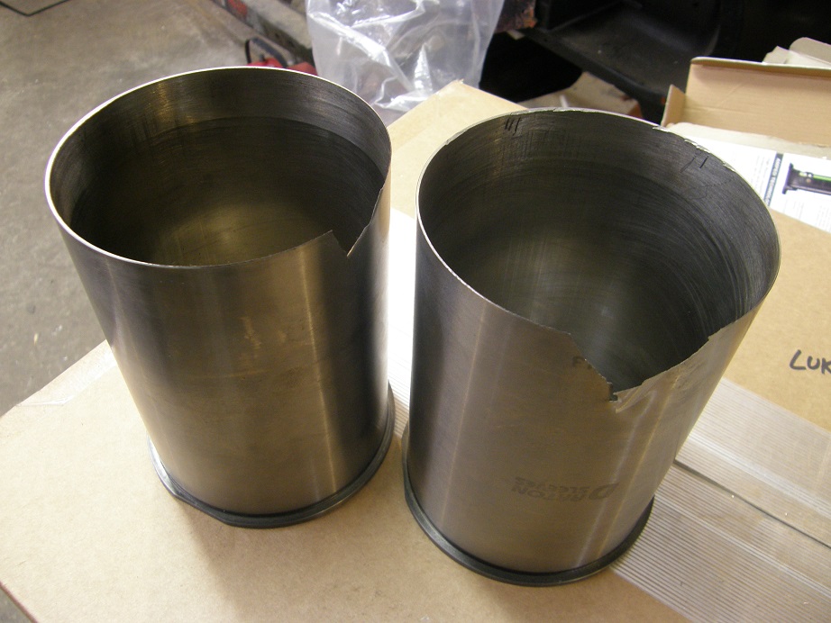
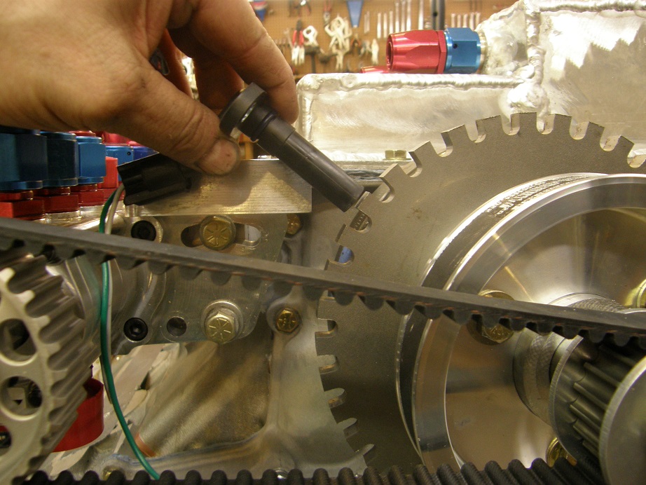
Last week I had been trying decide between cutting the spring pockets on the heads larger to make room for larger diameter springs, or buying new springs that would fit the existing spring pockets.  After my post last weekend I was looking at the heads in more detail and realized that in addition to cutting the spring pockets I would need to clearance some of the cam towers to make them fit; even with 1.55" diameter springs they had been too close and had required some clearancing.  I didn't really want to cut those any more than I already had, and when my machine shop guy said he was pretty busy this week, I bit the bullet and bought new springs, retainers, and spring locators.  They arrived on Wednesday this week, after I ordered them Monday morning; Comp Cams is really fast for shipments in most cases.  First thing I did was check the spring locators, and sure enough, they were just a hair too large to fit down in the spring pockets.  The springs themselves fit into the pockets nice and snug, thankfully.  Thursday and Friday nights were busy, but late Friday night I finally got out to the shop and started working on the spring locators.  I ended up chucking each one into my lathe and cutting it down in diameter by .025", and then they fit nicely inside the spring pockets.  Here's a picture of two of the locators; the one with the shiny edge has been turned down:


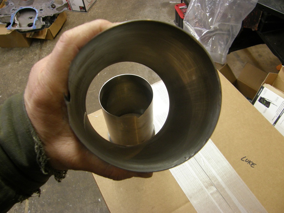
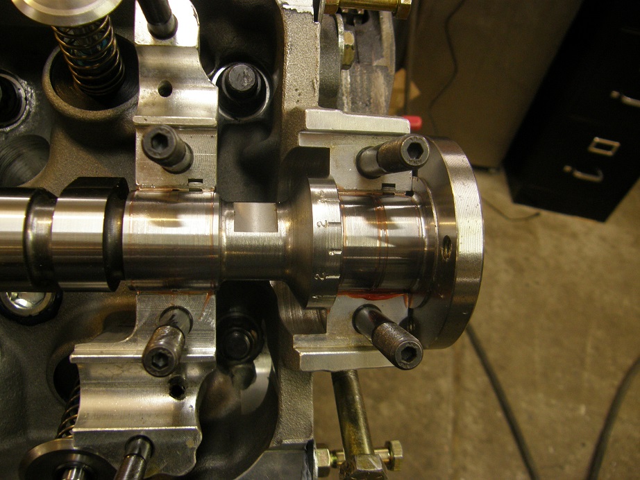
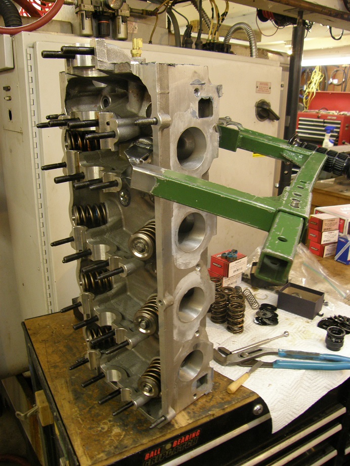
On Saturday morning I got an early start after seeing off the wife and kids, and started to get the heads re-assembled.  I try to be really careful while doing this, making sure to check everything like any good engine assembly shop would.  The springs all checked about the same at 245 pounds on the seat and 625 pounds open, and still had about .100" to go before coil bind.  I would have liked to run closer to coil bind if possible, but then the seat pressure would be getting too high; it is rather high as it is for this engine.  I also made sure to check the retainer to valve seal clearance; here's a photo of this check:


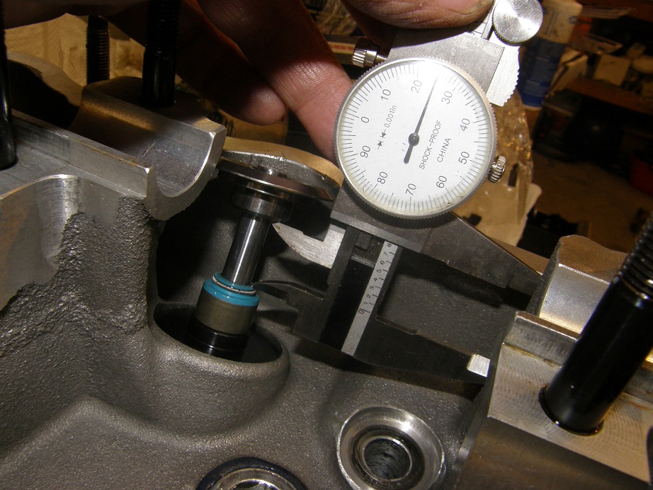
Net lift on my cams is 0.720", so I should have a little over .100" clearance to the seal.  I also assembled the heads with Manley +.050" valve locks to get the necessary installed height.  On the exhaust side I only need .030" shims under the spring locators, so using a standard valve lock would have prevented me from hitting the desired installed height, even if no shims were present.  The other option this presents is the ability to go to standard valve locks in the future if I want to increase the spring pressure.  I think I will let the dyno tell me if that is a requirement or not.

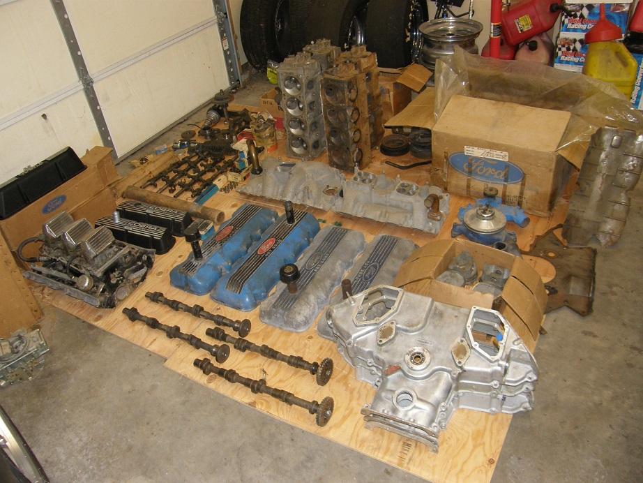
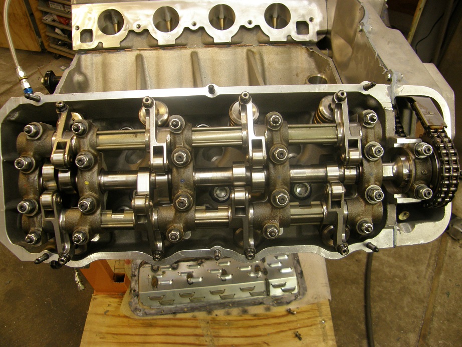
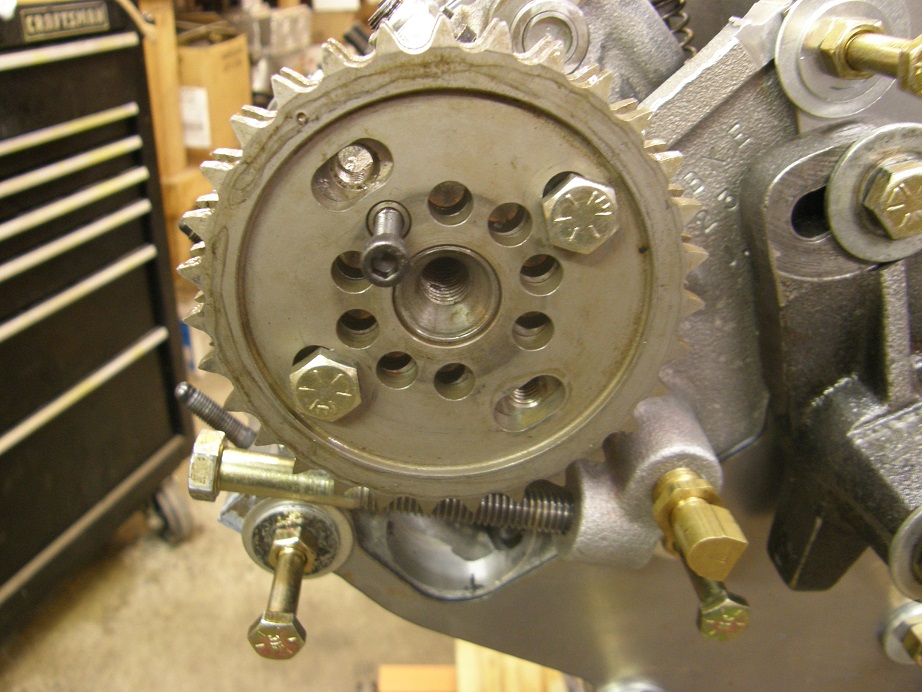
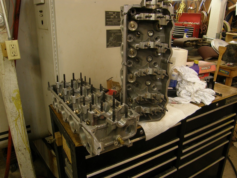
I worked on the heads all day, checking and re-checking various items, and finally by dinner time on Saturday I had the heads finished up and ready to install.  Here's a photo:


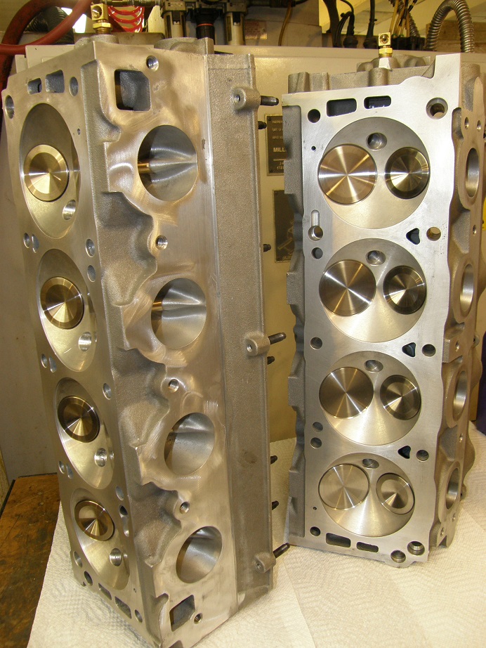
They look pretty good with those new Manley valves in there, and the flow numbers will be back up to normal now that the Ferrea valves are no longer in the heads.

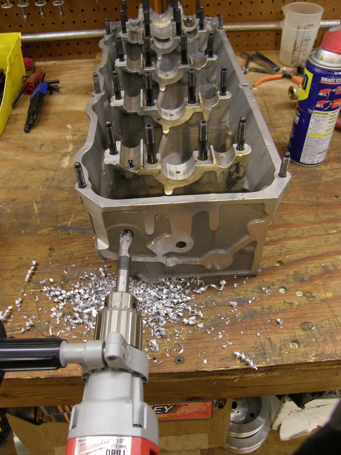
After dinner I decided to install one of the heads on the short block.  This is always an issue with this particular engine, because I have to use copper head gaskets on it.  The reason is that this block has a custom bore spacing; stock FE bore spacing is 4.63", but this block has been offset bored to 4.70".  This allows me to run a larger bore than would normally be possible, but it also means that stock head gaskets won't work, so custom copper head gaskets are required.  And, of course, copper head gaskets tend to leak on street engines.

Of course, the head gaskets are only one potential source of leaks with this engine; it is prone to leaks in a variety of areas, and in fact leaks in this engine took me out of the competition at Drag Week in 2011.  One reason is that when the block was offset bored, and bored for a larger diameter sleeve, on three of the cylinders we broke through the aluminum casting and into the water jacket.  This means that three of the cylinder sleeves are actually wet, with water on the other side of the sleeve.  On my first go-around with the engine in 2009, after installing the sleeves I used a chemical sealant to seal up the block.  This involved filling the entire block with this stuff, then pressurizing it to 20 psi for a few minutes to force the sealer into any gaps, then draining it all back out, and finally cooking the block at 200 degrees for several hours to cure the sealer.  This procedure worked, and the engine ran without problem from 2009 until 2011, when apparently the sealer gave up and the block started leaking water down past the sleeves and into the crankcase during Drag Week 2011.  After that debacle I took the engine completely apart and installed new sleeves; these sleeves have been cut with a groove on the back side of the sleeve and have an O-ring fitted.  So now all 8 cylinders have new sleeves with an O-ring seal at the bottom, which should solve the problem.  However, when I disassembled the engine I also found leaks up at the tops of the sleeves, where water was coming up between the sleeve and the casting at the deck.  This is a more difficult problem to fix; I didn't want to groove the top of the sleeves for a second O-ring because the top is where most of the compression pressure is.  This is where the difficulties with the head gasket come in.  The copper head gaskets I buy come with a special silicone sealer for use around the water jacket openings in the block and the head, but on this engine I'm also using it to try to seal around the tops of the cylinder sleeves.  This isn't an easy area to seal because it is right next to the O-rings that are cut into the tops of the sleeves, so the gasket isn't going to lay perfectly flat in this area.  After giving this some thought I decided to do the best I could with the silicone, and once I got the engine on the dyno I would run it with a radiator at first, rather than the dyno's cooling system, and use some Moroso ceramic sealer in the cooling system to seal up any leaks that may be there.  I'm also concerned about the heads on this engine; they leaked at first too, but have been sealed up with welding.  However, I don't know how much I can trust the welding after several heat cycles, so using the ceramic sealer may prevent problems there as well.

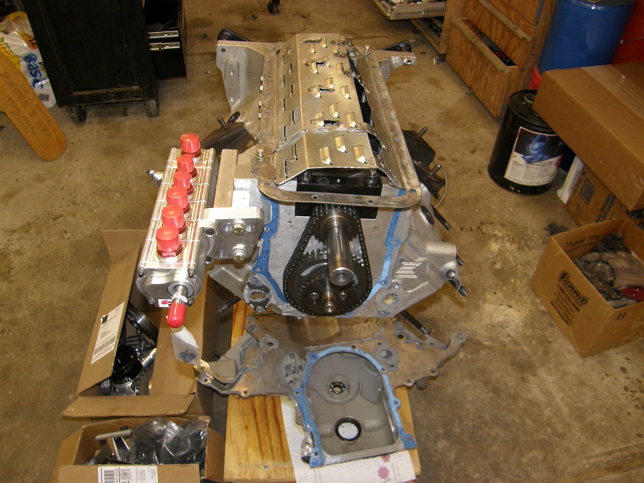
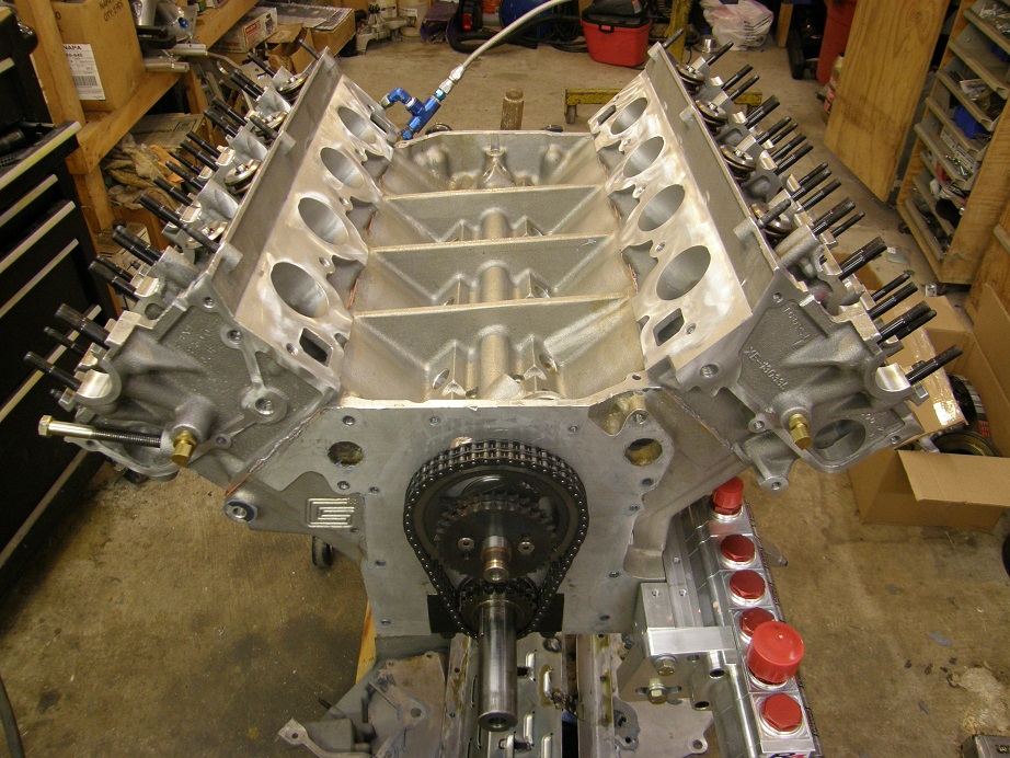
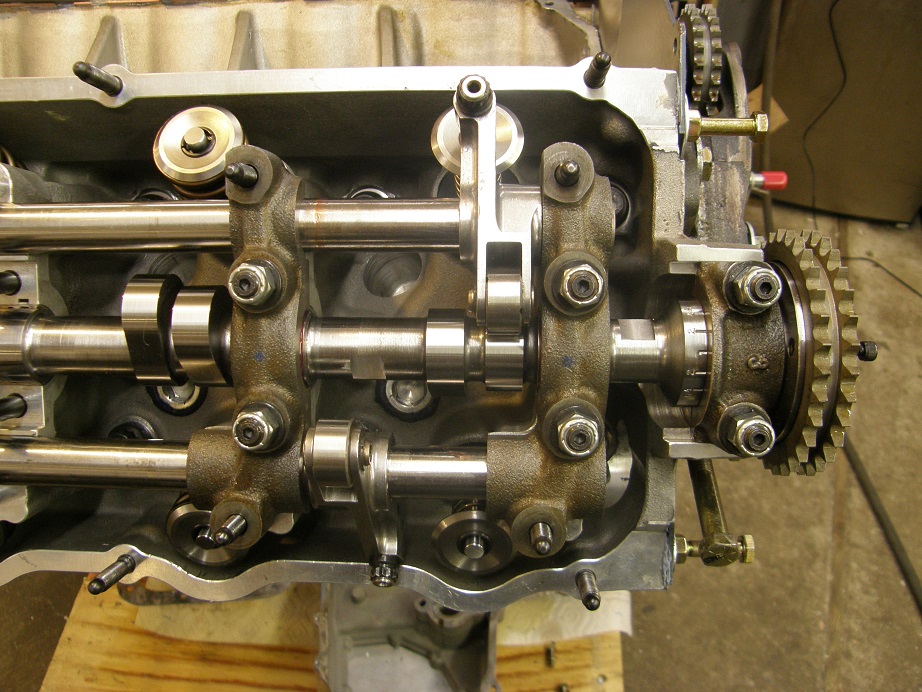
Trying to be as careful as I could, and working quickly so as to get the head on before the sealer set up, I got the right side head installed and torqued into place.  This morning I got back out to the shop by 8:00 and did the other head.  Here's a photo of the engine with both heads installed:


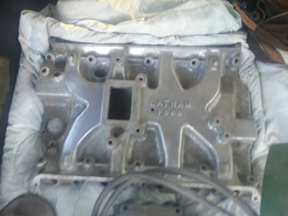
Next up on the assembly list is the backing plate for the timing cover.  This is the plate on the SOHC that seals to both heads, the water jacket openings in the block, and the normal FE timing cover position.  There are 23 bolts that go through this backing plate, and it has to be installed before the timing chain and gears can be installed, and the front cover put into place.  I've tried to do this in a single operation before, and it always seems like some of the sealer is dry before I finally get the front cover installed and bolted down, so I end up with leaks.  As a results I've started to do this assembly in two stages.  First, I get the backing plate installed with sealer, and tightened down with some dummy bolts, until the sealer is dry.  Then, with the backing plate stuck firmly to the block and heads, I can take my time assembling the gears and chain, and then have plenty of time to install the timing cover.

Here's a picture of the top of my assembly bench with the first five gaskets required for the backing plate installation.  I also have a bunch of dummy bolts laid out to hold the backing plate in position, plus the fuel pump gear and pedestal and the tensioner arm, which are also required:


Two of the gaskets above are SOHC specific, but the gasket around the primary timing chain and the water pump gaskets are standard FE parts.  I applied sealer to all the required surfaces and then stuck the gaskets to the block and heads.  In the picture below there are also two small blue gaskets that I cut from an old fuel pump gasket; these don't really seal anything but are used to space the backing plate out fromthe block and heads the same amount as the other gaskets, to avoid putting a twist in the backing plate:


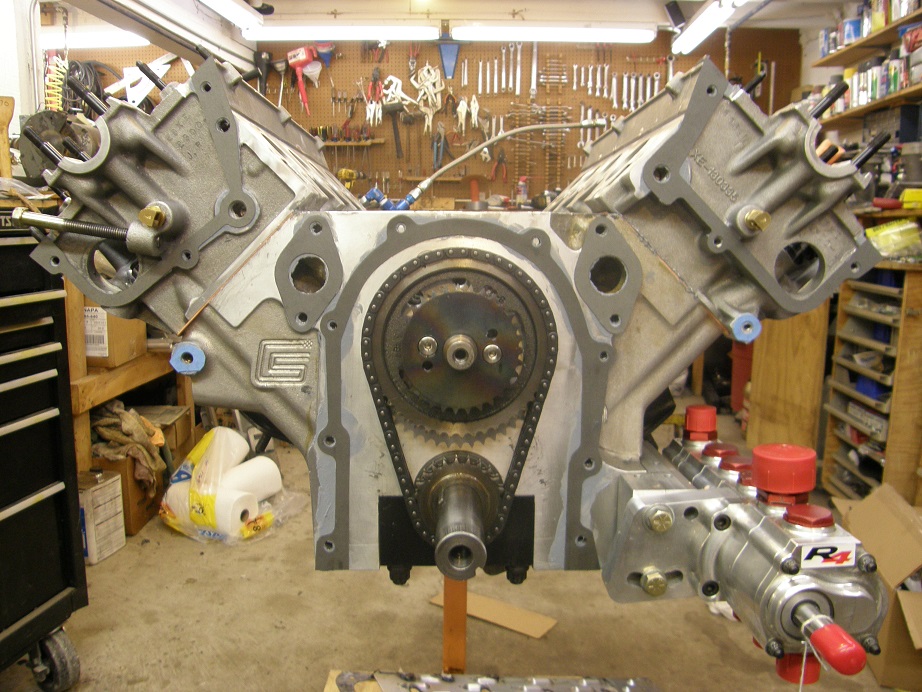
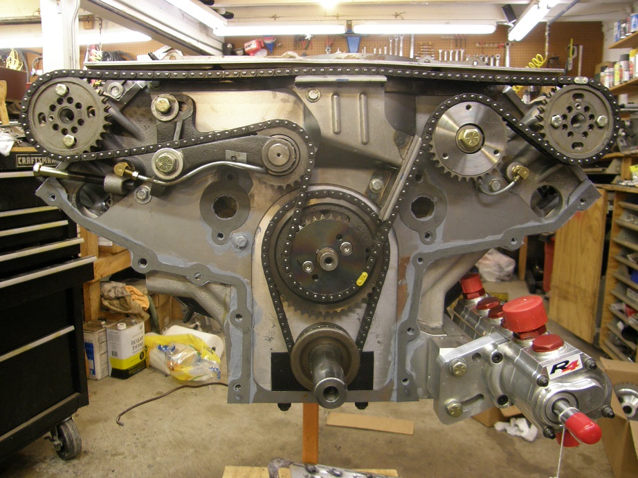
Next I put more sealer on the exposed gaskets to seal to the backing plate, and then installed the plate, working quickly to get all 23 bolts installed.  For most of the spots, rather than using a short bolt, I use a long bolt with a nut on it, and a couple of washers between the nut and the backing plate.  I just tighten the bolts in a few turns and then tighten the nuts to clamp the backing plate to the block and heads.  Here's a picture of the engine with the backing plate installed, and all the temporary fasteners in position:


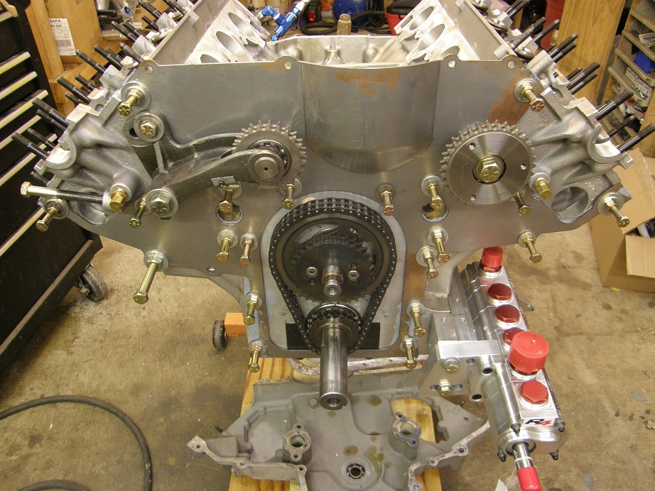
I'm going to let this dry for a couple of days, and then start the fun stuff, which is installing the cams, assembling the chain drive, and installing the front cover.  Prior to the front cover installation I need to drill a hole in it for a cam sensor, because I'm going full sequential EFI on this engine.  Once the front cover is installed I can tighten up the chain and check piston to valve clearance, and then install the last two valvesprings in place of the checker springs on cylinder 1.  With luck I will get all that done next weekend, and then be ready for installing the oil pan, the intake manifold, and the front end parts of the engine...
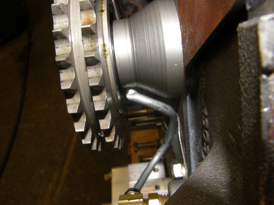


217
The Road to Drag Week 2014 / The Road to Drag Week 2014 - May 4
« on: May 04, 2014, 12:44:41 PM »
This week I put together a detailed schedule of what I have to do to get the engine finished up and on the dyno, and the car back together and running by the end of June.  As usual, it looks do-able, and as usual the plan will probably go out the window as soon as something unexpected goes wrong.  However, I'm going to try to hang with it as much as possible; this year I've just GOT to get to the track a few times before the event.  This week I got the great news that my friend Steve, who went with me at Drag Weeks 2005 and 2006, was able to get his vacation for the week approved, so he is going with me this year for Drag Week #10.  We plan to hit the track together several times before the event.

Back to the engine work, one of the upgrades this year is addition of a dry sump system, with the result that at all times when the engine is running, the pressure in the crankcase is going to be lower than atmospheric.  This means that the seals will have to be in the engine backwards, because part of the way the seal works is to use the higher pressure in the crankcase to force the seal lip against the crankshaft.  With the vacuum from the dry sump in the crankcase, the pressure differential is reversed, so the seal has to be reversed.  So, on Saturday this week I got to work flipping the rear main seal around.  On the Shelby blocks the fit between the caps and the block is really tight, so you have to use a slide hammer to get the caps loose.  Here's a photo of the slide hammer attached to the rear main cap as I'm pulling it out of the block:


After I got the cap off I tried without success to push on the end of the seal that was already installed, but it wouldn't budge.  So, I ended up loosening the remaining four main caps so that I could pry the rear of the crank up just a little bit, and rotate the seal out of place.  Then, I reversed it and stuck it back into the groove.  It took me an hour to get all the caps loose, and 30 seconds to reverse the seal  ::)  I reset and retorqued caps 1-4, and now I just have to install the rear main cap later today (with its seal half reversed also), and then this little job is finished up.  The front seal will be much easier, of course, because the timing cover is already removed from the engine.

During the week this week I had taken the few spare moments that I had and finished welding up the oil pan, to convert it to work with the dry sump system.  This is undoubtably the world's ugliest dry sump pan:


This is actually the third iteration of this oil pan.  I ran this originally in my Galaxie, where it was a rear sump pan to clear the front-steer rack that I have installed in that car.  Then, when I swapped the motor into my Shelby clone, I had to modify the pan extensively, in order to fit around the rear-steer rack setup that is installed in that car.  Both of those installations were wet sumps, so this time I had to cut the oil pan down while still keeping it set up to fit around the rack, and add the fittings and pickups for the dry sump lines.  It was a major pain, and I'm definitely not happy with the appearance of this thing.  Further, I haven't leaked checked it yet and I will still have to do that and weld up any problem areas, so its only going to get uglier.  But if it works, and doesn't leak in the car, I guess I'll be satisfied with it.

After the seal swapping episode yesterday, today I tackled disassembly of the cylinder heads.  As mentioned last week I wanted to get rid of the Ferrea valves and install the Manleys that flowed so much better.  I've been doing my own cylinder head setup on these engines for several years now; here's a picture of the valve spring compressor set up on one of the heads:


The spring compressor is a standard one that has been modified to fit in the tight confines of the SOHC heads.  After getting all the valves removed I also had to remove the valve seals, spring seats, and shims, because the new springs I wanted to use with the new cams for this engine were a little heavier than the Comp 943 springs that these heads were originally set up with, and would require different shims.  I was planning to use the Comp 26099 springs. I had gone to the trouble of sending an SOHC head with one of the new cams to Bill Conley last year, so that he could run it on his spintron machine and check for valvetrain stability.  Bill ran it with both the 943 springs and the 26099 springs, and the 943 springs just couldn't hack it with the new cam.  But the 26099 springs looked good.  I have a set of new 26099 springs here that I purchased for use with another set of SOHC heads that were built by Dove (the 26099 springs fit on the Dove heads), so I grabbed those and started to get set up to install them.  Right away, I discovered a problem.  These heads, which are Coon heads, only have the valve pockets machined for a maximum spring diameter of 1.55", and the 26099 springs are 1.63" in diameter.  So, my hopes for getting the heads completely assembled this weekend have gone out the window. 

I have two options here.  One is to take the heads in to my local shop and get the spring pockets opened up to 1.63".  The other option is to buy a set of springs that will fit the heads, like the Comp 26115 springs, that have about the same specifications for open and closed load as the 26099 springs.  The problem there is that I'll be out $800 to buy springs, retainers, and spring seats.  Also, I have a couple of sets of the 26099 springs, plus extra retainers, and having spare valvetrain parts during Drag Week is a big plus.  So, I think I'm going to see if I can get the heads cut for the 26099 springs quickly; if there is a delay on this, then I'll have to buy the new springs and retainers.

With the heads completely bare I went to the next task, which I have to say required some intestinal fortitude.  Here is a picture:


You kind of hate to drill a big hole in a set of heads that you've got $7500 in between the price of the castings and all the porting work!  But my dry sump setup is a six stage, and it needs a scavenge line connected to the back of each cylinder head.  So, after drilling the hole, I tapped it for a 3/8" pipe thread.  Here's a picture showing the fitting temporarily screwed into place:


After that was done I thoroughly cleaned each head to get rid of all the old sealer and any remaining traces of metal shavings; here they are, ready for a quick trip to the machine shop:


I'll find out Monday if I can get the valve pockets cut in time, or if I need to go to the other set of springs.

Saturday night was my daughter's junior prom, and last night while at the dance she texted me asking for photos of my Shelby clone.  Obviously, she was trying to impress some young man at the dance LOL!.  I dug up some pictures from Drag Week 2011 and sent them to her.  I had forgotten how nice the car looked back then; I will post the pictures below, and come back to this thread for motivational purposes when my enthusiasm for the project starts to flag ;D  
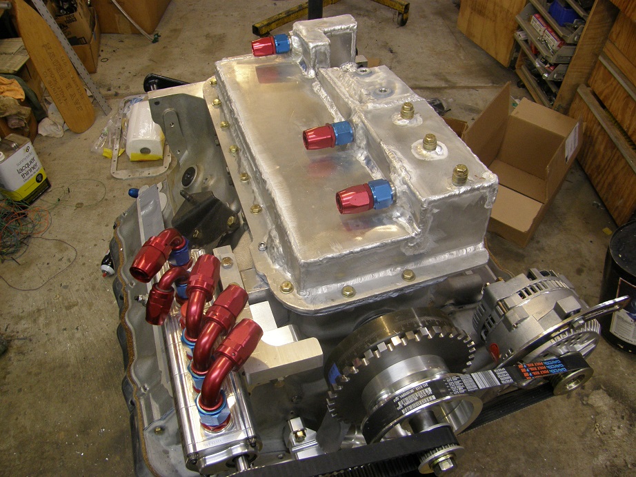
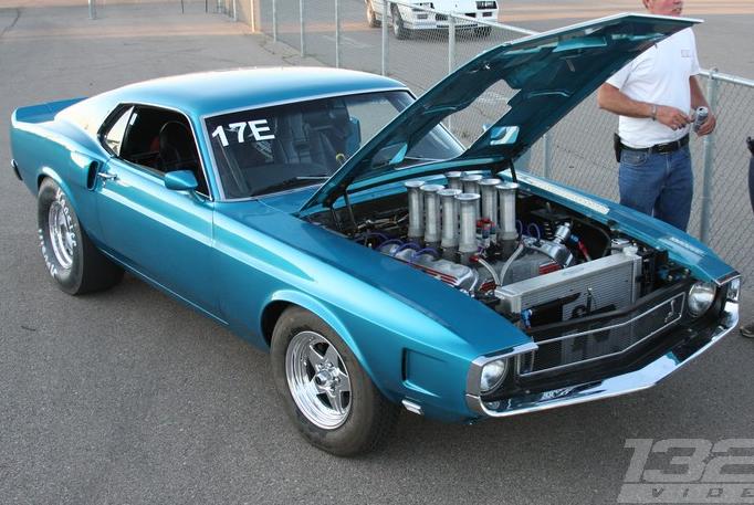
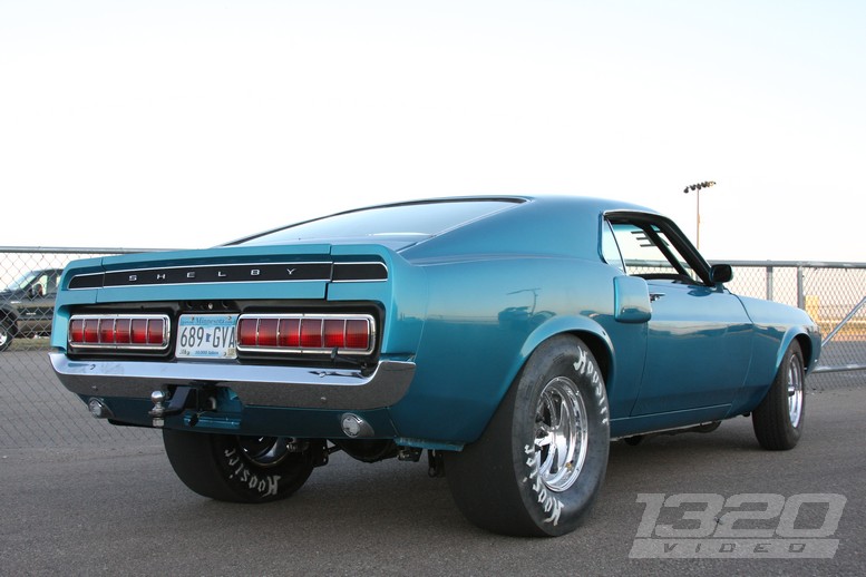
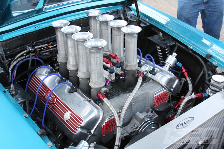
All the pictures below were taken by Kyle Loftis at 1320 Video:


Now, its back to a little custom intake adapter work...


218
The Road to Drag Week 2014 / The Road to Drag Week 2014 - April 27
« on: April 27, 2014, 05:05:54 PM »
Ever since last September I've been thinking about Drag Week 2014.  I came back last year pretty disappointed in my performance, and it was clear in restrospect
that I just hadn't been very prepared for the event.  This was the same situation as 2012, when I tried to bring three cars but didn't make it with any due to
 last minute problems, and 2011, when my Shelby clone was pretty much brand new and I had thrashed like mad just to get it finished before the event.  Last time
I won my class, in 2009, I'd been much better prepared.  I had resolved this year to make a better effort, so that I could at least finish the race.

Watching the message boards and Hot Rods website it was clear that Drag Week had mushroomed in popularity.  Last year all the spots sold out in 8 hours; in
previous years they had never even sold out all the spots.  This took me by surprise last year, and I ended up not getting registered; I had to go down to Bowling
Green with the car and hope somebody cancelled so I could get in.  This year the talk was that even more people wanted to attend than last year, so last fall I
started to get worried about even being able to sign up.  With my intake manifold project going also, this uncertainty had the unanticipated effect of keeping
me from getting too motivated on getting my car done for the event.  I sweated this situation out for most of the winter while the race car sat, but finally
Hot Rod came out with a statement in March that they would give a week's warning on their web site before registration went live.  Again I was concerned because in the
middle of April I was going to be in Europe for 10 days, and didn't know if I would have the time, or the internet access, to get online and register if it happened to be
while I was there.  Fortunately for me, my trip came and went without any news from Hot Rod.  Then a week ago the registration information was posted:  Saturday, April 26,
9:00 AM Pacific time.

Well, with all these people wanting to register I didn't know if I could even get in!  So on Saturday at 9:00 AM Pacific time, there I was hitting the refresh key
over and over again, waiting for the registration link to go live.  As mentioned elsewhere all the spots for DW14 went in 8 minutes, but I was lucky enough to get in.

So, now I have a car that is apart, that needs to go back together and get to the track as soon as possible, so that I can be a little more prepared this year when
the event finally rolls around.  I decided to put together another Road to Drag Week board to chronicle my progress.  The car I want to bring is my '69 Shelby clone,
but if worst comes to worst and I don't get it ready in time, I can bring my Mach 1 instead, which is essentially together, needing only about 10 hours of work to
finish the wiring project I started on it last year.  But I'd really rather bring the other car.  Here's a couple of photos of it in its current state:


Right now I'm working on getting the oil pan for my dry sump setup finished up; once I have that done I have to go through the heads, replacing the Ferrea valves with the Manleys that flow so much better, then get the whole thing put together, and finally put the sheet metal intake that I built for this engine a couple years ago on it.  Then, I have to mount the crank and cam sensors, and get the MS3X EFI system all wired up so I can dyno the engine.  Hopefully the dyno work will go smoothly and I can get that done in a weekend.  I'm targeting the end of May for the engine to be together and dynoed, and ready to go in the car.

Then of course I have to put the car back together, and change the wiring all around to remove the ems-pro EFI system and install the MS3X system in its place.  I also need to replace the rear end gears with a set of pro gears (there are street gears in it now), and get the car running and driving.  Hopefully I can get all that done by the end of June.  If I can keep that schedule I'll have a few weekends to sort the car out at the track, and plenty of time to drive it on the street, before I have to head to the event in September.  My history of keeping schedules is miserable, but I'm going to give it a try.  I guess even if I'm a little late, as long as I get some track time on the car it should be OK.

We will see what happens.  I will try to post a weekly update on my progress - Jay

219
FE Technical Forum / Pictures from the FE Race and Reunion?
« on: April 25, 2014, 09:59:59 PM »
If any of you lucky guys who are attending can post some pictures from the event, I'm sure the rest of us would love to see them.  I sure would...

220
FE Technical Forum / Latham Supercharger Setup for the FE
« on: April 25, 2014, 09:53:05 PM »
A friend of mine had a party tonight and one of his guests brought the Latham supercharger setup for an FE pictured below (Sorry for the poor photo quality, but it was the best I could do with my cell phone camera).  I've only seen one of these one other time, back in the '80s at one of the Ford Performance Club of America shows in Columbus, Ohio.  The one I saw also ran the supercharger with V-belts if I recall correctly, and when it ran it sounded like a jet engine.  I guess that the principal of operation of one of these superchargers is similar to a jet turbine.  This setup had the FE-specific intake, the supercharger, four sidedraft Carter carbs, and the drive setup, which looked like about an 8:1 or 10:1 step-up of the crankshaft speed to the supercharger (just a guess on that; I didn't get a chance to measure the pulley diameters).  The carbs were interesting; apparently these sidedraft Carters were used on the early Corvettes with the 6 cylinder engine and they are very valuable.  A stock distributor won't work with the blower in this position, and I was told the original setups used a right angle distributor with this arrangement.  Anybody know for sure on that, or have any pictures of one of these on a running engine?

The whole setup was polished, and I can't think of a cooler looking induction setup for an FE in an early Ford performance car.  It was really great to see one in person.  I'd sure love to have an engine with one of these on the dyno at some point. 


221
FE Technical Forum / Questionable Engine Builders
« on: April 20, 2014, 09:22:04 AM »
Every once in a while I see something from a "professional" engine builder that is nearly beyond belief.  Yesterday a friend of mine brought over some pieces from an engine that was built by a now-defunct shop called Pop's Performance.  I've heard that these guys were really bad, but still couldn't believe what I saw.  They started with a brand new Pond aluminum block, and decided to bore it to 4.375".  That is way, way over the recommended maximum bore specified by Pond.  The engine went together and according to my friend (who is tasked with fixing this mess), the engine didn't make good power and it smoked like hell.  After teardown it was clear that the steel sleeves in the block had been way overbored.  The sleeves were all pulled out of the block; here are a couple of them:


First thing is, after the overbore those sleeves are paper thin on one edge.  No support left there at all.  Second, they didn't even bore them on center; one side of the sleeve is much thicker than the other, although not thick enough.  At the bottom of the sleeve I could squeeze it out of round with my hand:


The customer paid $25K for this engine.  It still amazes and saddens me that in this day and age some businesses will be this dishonest with their customers.  Buyer beware...


222
Non-FE Discussion Forum / European Fuel Prices
« on: April 20, 2014, 08:47:11 AM »
I just got back from a 10 day business trip to Europe.  I spent most of the time driving around through Switzerland, Austria, Germany, and Denmark.  As a result, I saw plenty of sights like the one shown in the picture below:


This pricing is in Euros per liter.  The exchange rate is currently $1.38 per Euro, and there are about 4 liters per gallon.  Doing the math, at 1.539 Euros per liter for 10% Ethanol fuel, this is a price of $8.49 per gallon!

Glad to be back in the good ol' USA  :D

223
FE Technical Forum / The big score!
« on: March 08, 2014, 12:25:28 PM »
A few months back a local friend of mine contacted me, giving me the number of a guy who lived about an hour away and had a big collection of SOHC parts he wanted to sell.  This gentleman had been collecting these parts since the mid 1970s, with the intention of building an SOHC powered street rod.  He recently decided he was never going to get around to the project, and decided to sell.  He had a lot of nice parts, but I didn't need them, so I made him a low end offer that I knew he wouldn't accept, and left. 

Fast forward to a couple of weeks ago, and he gave me a call.  He'd been trying to sell the parts as a single lot, and hadn't been having any luck.  He had decided to accept my offer, if it was still available.  At the price I had offered him, I just couldn't pass up the deal.  Today I got the parts.  Here are some pictures, and yes, that is a brand new, in the Ford box, 427 sideoiler block:


Two sets of factory SOHC heads, one iron, and one the extremely rare aluminum factory heads.  Those are magnesium valve covers.  There are three timing covers, one 4V intake, one 8V intake, a complete set of factory adjustable rockers, one set of factory cams and another set of cams of unknown origin (maybe Crane?), water pumps, a complete set of pistons, timing chains and gears, pulleys, you name it.  Also thrown in was the complete 406 tripower setup, some valve covers (the FE valve covers are new in the Ford boxes), and FE cam and lifters (also new in the Ford boxes), etc. etc.  Here are some more pictures:


There are enough SOHC specific parts here to make a complete, factory SOHC engine, except for the crank, rods, block (the new block is a normal factory block, not SOHC specific), and factory carb, and I happen to have one of the factory carbs for the 4V setup.  The only downsides are that one of each of the heads has been damaged and repaired, and one timing cover has been damaged and repaired. 

I don't know what I'm going to do with this stuff, but right now it looks pretty cool just sitting on the floor of my shop  :)


224
Member Projects / U13 Bronco
« on: February 09, 2014, 08:58:00 PM »
I talked to a guy name Jim from Dallas today, who was interested in an intake adapter.  He was telling me about a Bronco that I'd never heard of, called a U13.  Apparently these were very rare and hard to find vehicles, but he has several.  One of them he got was kind of a basket case, so he is turning it into a race car.  And, of course, he will install an FE!  Pretty cool.

He sent me the following pictures.  The first one is a U13 Bronco that he restored and sold at Barret Jackson.  The other four pics are of the current project:


225
Warning - Buyer Beware / Question for the members regarding this board
« on: January 29, 2014, 08:53:31 PM »
This complaints board doesn't get a whole lot of topics (thankfully), but as you probably have noticed the recent posts have focused on a couple of well known vendors, DSC and Survival.  My inclination on this is to let these kinds of topics stand, because if I deleted them it would be viewed as dishonest by at least some of the members here.  On the other hand, I have had personal experience with both of these vendors that makes these posts seem a little unfair.  I have purchased a few parts from DSC, and had no problems, and I have purchased a LOT of parts from Survival, again with no difficulties whatsoever.  The responses under these topics lead me to believe that most others here have had the same experiences as I have.

It is a truism that you can't please all the people all the time, and any business is going to have at least a few unhappy customers.  Sometimes these customers are not going to be happy no matter how they are treated.  What do you guys think I should do about this?  Some options:

- Limit the posts to complaints about private parties, and delete any posts about vendors?

- Leave the posts up for a limited amount of time, and then delete them?

- Leave the posts as they are, and let others chime in with experiences counter to the complaint?

I'm open to suggestions.  My original reason for starting this board is to warn people away from dishonest individuals and substandard products, but the complaints about DSC and Survival certainly do not meet that criteria...

Edit:  Also, if you have something to say but would rather not respond publicly, send me a PM.

Pages: 1 ... 13 14 [15] 16 17 ... 25