Dyno weekends tend to be exhilarating and frustrating all at the same time, and this one was surely that! When I wrote my last update I figured I'd be spending all weekend wiring the EFI system onto this engine, and would be lucky to get it running. That all went out the window on Monday when I emailed Scott Clark and told him that I probably wouldn't be ready to run this weekend, because I didn't have the engine wired and I wanted to have it up and running before he drove up with his double throwdown, triple whammy 8 oxygen sensor tuning setup. But in his return email Scott pointed out that he was not tied up on Friday, and if I could take Friday off he would come up and help me wire the engine, and we could get it running and tuned over the weekend.
Well, I had another errand that I had to run on Friday morning anyway, so I had already taken the day off. Scott had to drive up from Omaha to my place, and I figured with both of us working on the wiring we might be able to knock it out by the end of the night on Friday. So we made the arrangements, and I spent some time during the week getting all the mechanical stuff done for getting the engine running on the dyno. On Thursday night I was clipping part of the wiring harness out of my Shelby clone and putting it in place on the engine, and at the end of the night on Thursday, for once it appeared that I had overestimated the time it was going to take to get the project done; it seemed like between the two of us Scott and I could indeed get the wiring done on Friday.
Friday I got back from my morning errand by 11:00 or so and started working on the wiring shortly thereafter. Scott showed up around 2:00 and between the two of us we had it finished up and were ready to start the engine by 6:00 PM. About that time another guy that Scott knows, Mark Dahlquist, also showed up. He drove down from Fargo ND to meet up with Scott and drop something off with him, and he hung around to help out with the engine. I was really lucky to have both of those guys here to help out. Some of you may know that Scott is kind of the EFI tuning guru for a lot of motorsport teams; he tunes for Bischoff and Ray Barton at Engine Masters, and of course those teams always do well. He also tunes for some of the Bonneville teams, and he is actually making his living at this point tuning engines. I hadn't met Mark before this weekend, but he is also an Engine Masters competitor; his first year was last year, and he finished 9th (I think) with a Pontiac engine, with Scott tuning the engine for him. The most recent issue of Popular Hot Rodding has a writeup on Mark's EM engine. Talk about qualified assistance! I'm practically a newb compared to these guys.
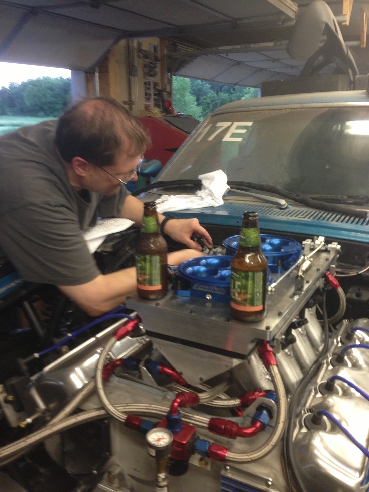
Anyway, after Mark showed up Scott spent some time setting up the Megasquirt MS3X EFI system, and then we tried to start the engine. First time out on this stuff you are always concerned about getting a good signal from the crank sensor. I was using a Ford VR sensor on the crank target wheel, and a Cherry digital sensor for the cam position sensor. After several tries we got the engine started, but I shut it off right away because we hadn't put coolant in the engine yet. When assembling this engine I had been concerned about internal water leaks, so I had decided that the first thing I was going to do was to run the engine on the dyno with a radiator, so that after the water temp came up I could dump in some Moroso ceramic sealer and circulate that through the engine for a while to seal up any seepage that might be present. After we knew the engine would start, I got to work setting up the radiator and the cooling hoses. Mark had the idea to put some hooks in the ceiling and hang the radiator from a couple of tie down straps; that worked out very well, and shortly thereafter I had the cooling hoses attached to the water pump and the thermostat housing, and the electric fans wired up. I filled the engine with distilled water at that point, checking carefully for any leaks, but there weren't any, so that was a good sign.
Next we fired up the engine, but Scott was concerned about the crank signal because the engine wasn't running that well. The MS3X system has a diagnostic mode where you can watch the signal from the crank sensor, after conversion to a digital signal (the Ford VR sensor puts out an analog or sine wave signal). This is just like having an oscilloscope screen on your computer so you can watch the crank and cam signals. This diagnostic mode was showing errors with some of the teeth on the target wheel; the sensor was losing teeth, and so the missing tooth on the wheel was not being detected properly. We messed around with the sensor airgap to try to resolve this problem, and it seemed like it mostly went away, but still would give us some intermittent errors when the engine was running. In any case though, we could get the engine started, and it sounded pretty good. Finally around 10:00 PM we just decided it was getting too late and that we needed to run the engine to get the sealer circulating; I didn't want to leave it overnight with water in it and no sealer, and also I wanted to circulate the sealer and then later drain the coolant out of the engine, per the sealer's instructions. So, we fired it up with a less than ideal crank sensor signal and started warming up the engine. It wouldn't idle much below 1500 RPM at this point, but that was OK for Friday night's purposes. After the engine was warmed I dumped in the bottle of sealer, put the cap on the radiator, turned on the electric fans, and let the engine run. The CVR water pump seemed to keep right up with the cooling system; it did gradually warm over 30 minutes from 180 degrees to 210 degrees, but by that time the sealer was well circulated and we had run the engine twice as long as was recommended by the sealer instructions, so we shut it down and called it a night. Scott and Mark took off, and around midnight I came back out to the shop, drained the water out of the engine, and then went to bed.
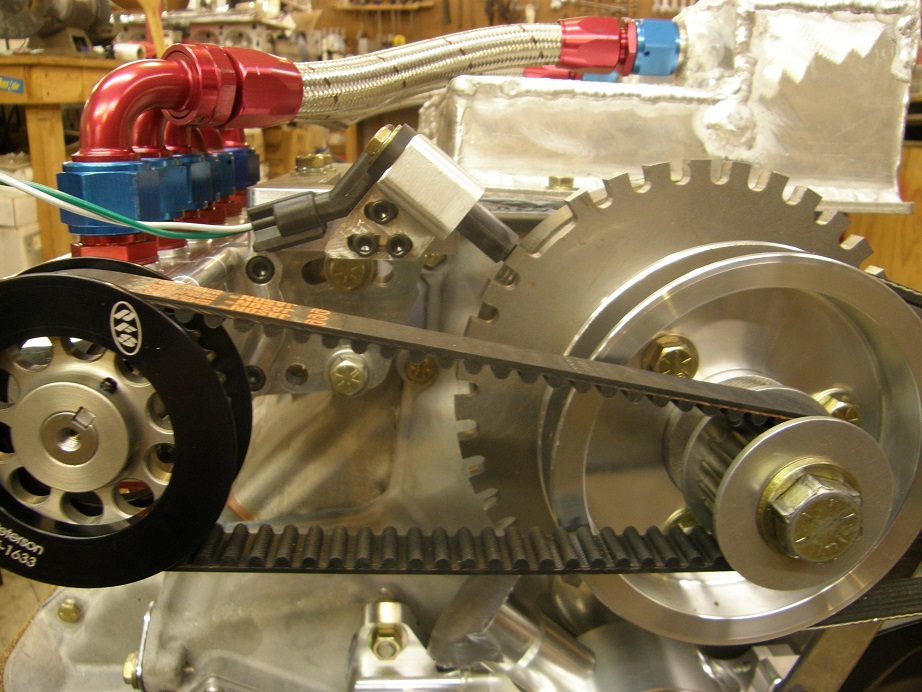
Saturday morning I was up early, taking the radiator off the engine and hooking up the dyno's cooling system. After Scott and Mark arrived back we got to work on the startup procedure for the engine again. We continued to have trouble though with the crank signal. For a while it would work just fine, with no errors, then suddenly we would get bunches of errors all at once, and the engine would sound like crap. One thing we tried was changing the lead on missing tooth of the crankshaft target. My target wheel, like the Ford ones, has a tooth every 10 degrees around the wheel, with one tooth missing to allow the EFI unit to sync up to the wheel, and know where top dead center is. I had the tooth #1, which is the first tooth after the missing tooth, set for around 65 degrees BTDC. My target wheel is drilled for multiple mounting positions, in 20 degree increments, so we tried advancing the target wheel so that tooth 1 was at 45 degrees, and retarding it so that tooth 1 was at 85 degrees, but still couldn't get a good consistent crank signal. This was the same issue that was dogging me at Drag Week in 2011, so we really needed to get this problem solved. Scott began promoting use of another Cherry digital sensor, like the one we were using for the cam sensor, on the crank; he had recently had good luck with those. I did have one spare Cherry sensor, so finally I installed one in place of the Ford VR sensor. There was an immediate improvement in the cranking signal from the sensor, and the engine began starting much more easily. We had it up and running for several minutes at a time while Scott tuned the A/F ratio and logged the sensor diagnostic data. We were still seeing some drop out of the crank signal, though, so Scott thought we should try moving the target wheel again. After I did that, suddenly we had nothing for signal, and the engine wouldn't start. Mark went into the dyno room and wiggled the sensor, and found that it was loose! This was my fault; I had only put the nuts that held the sensor in place finger tight, and they had come loose and the sensor had started to wobble around. I tried to put the sensor back in its original position, but it looked like the sensor body had been dinged by the target wheel, and it just wouldn't work anymore. So, our crank sensor was no longer working.
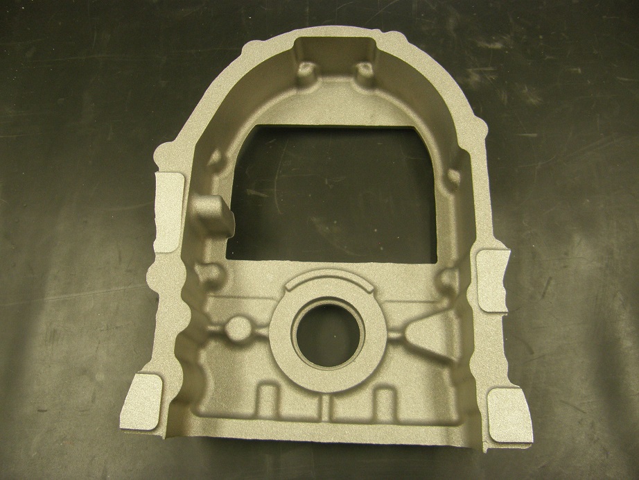
We thought about going back to the Ford VR sensor, but I did have a couple of other digital output sensors made by Hamlin that would also work. Unfortunately the Hamlin sensors wouldn't physically fit in the crank sensor mounting bracket that I had machined for this engine. So, in the end what we decided to do was take the Cherry sensor out of the left valve cover, use that one as the crank sensor, and put one of the Hamlin sensors into the valve cover to act as the cam sensor.
All this screwing around with the sensor took the whole morning and most of the afternoon, but when we got the new sensor configuration set up it seemed to work really well. Finally we were ready to make some dyno pulls. We started with pulls from 3000-5000 RPM, and gradually worked our way up to 5000-7200. The engine sounded really good, but was down just a little bit on power compared to what I was expecting. (By the way, this will be disappointing for some of you guys but I won't be sharing any of the dyno results from this engine just yet. There are Drag Week competitors watching this web site, and I don't want to tip my hand before the event. I will post the dyno results on this blog in September, after Drag Week has started.) While we were doing these pulls Scott was messing around with a software feature in the MS3X called VVT. VVT stands for variable valve timing, and it allows the MS3X to control the variable valve timing actuators found on some modern engines. What he was discovering, though, was that despite the fact that this engine doesn't have VVT actuators, the MS3X can log the position of the cam sensor during a pull. This would allow us to see the cam with the cam sensor on it advancing or retarding during the pull!
Back in 2006, on the second SOHC I ever built, I added proximity sensors and targets to the crank and both cams, and ran multiple experiments over a 4 week period trying to determine exactly how much the cams were moving with engine speed. The datalogging capability I had back then was SLOW, and so I ran the pulls really slow, and tried to get data every 500 RPM or so. It was quite the torture test for the engine, and gave me some surprising results. What I found was that while the right cam retarded with RPM (as everybody always said they did), the left cam actually advanced with RPM. This led to about a 3-4 degree variation in cam timing between the two cams, so ever since this I've been setting up my SOHC engines with the right cam advanced 3-4 degrees compared to the left cam. The two graphs reprinted below summarize all this data:
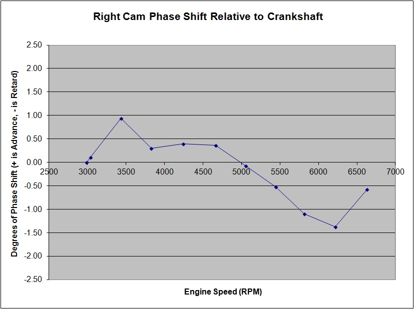

The "calculated" vs. "measured" data in the second chart refers to calculating the difference between the two cam signals when they are compared to the crank signal, and then a directly measured difference between the two cams. The data was taken on different days, so there are some minor differences, but the general trend is the same. Now that we could see this same data logged directly from the EFI system, I was anxious to get some confirming data.
The cam sensor was on the left cam, so we were expecting it to advance. After the next pull, the data seemed to show that the left cam was retarding, and by quite a significant amount! However, there was some question about the data itself; could the direction be wrong? We weren't sure, but in any case we were seeing something like 8 degrees of change in the cam phase. Yikes!
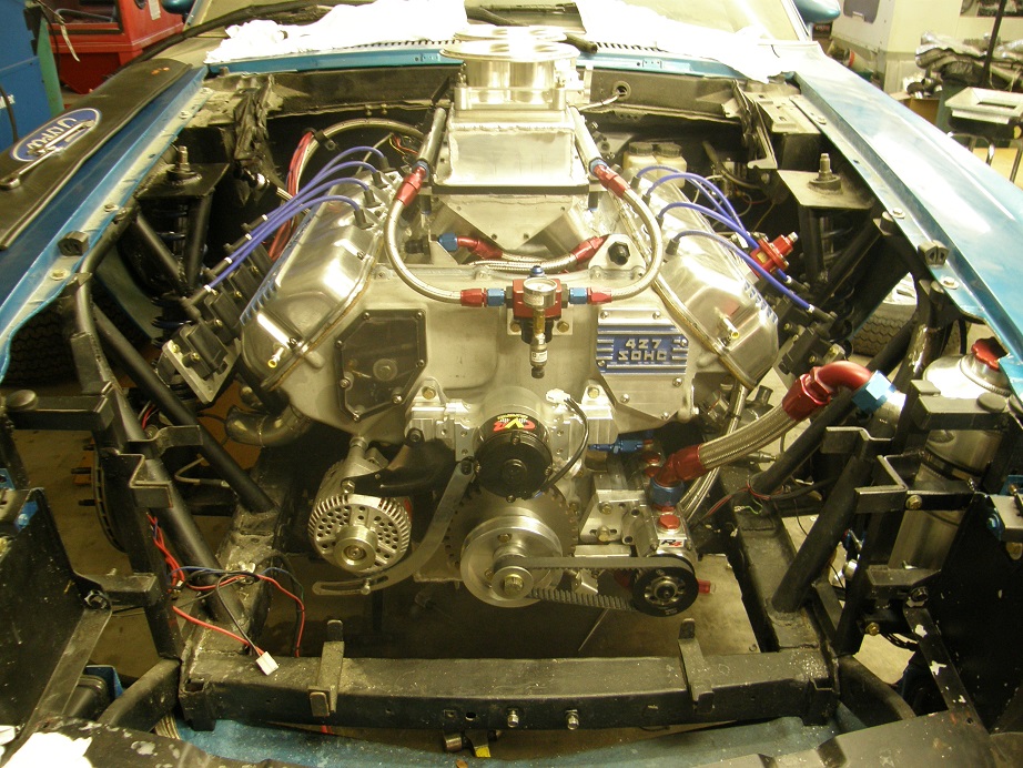
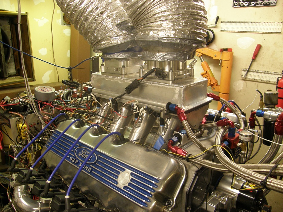
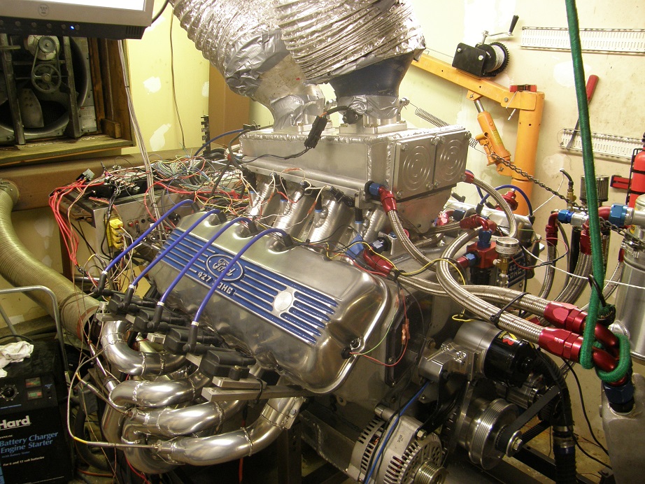
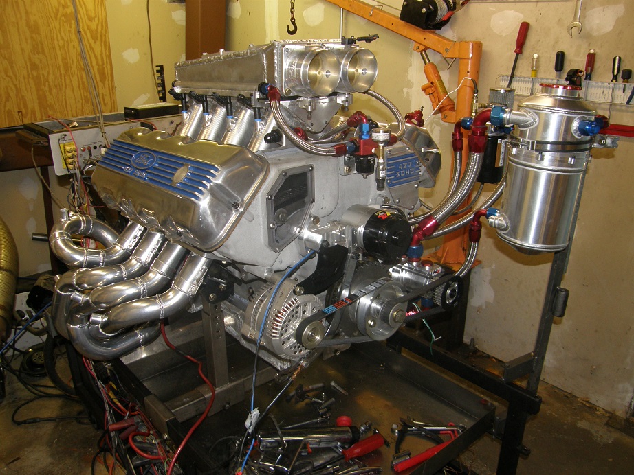
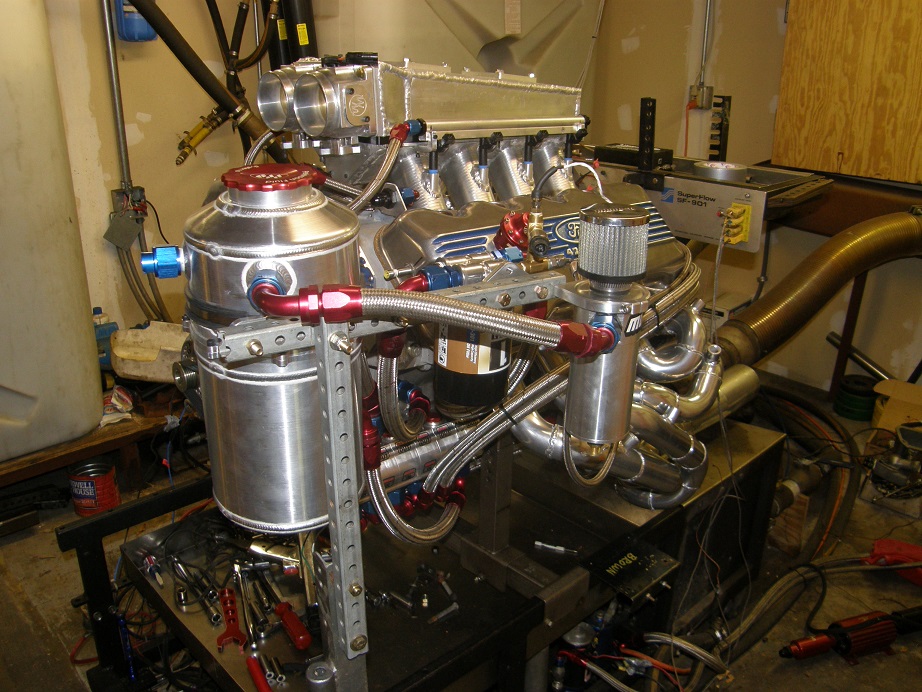
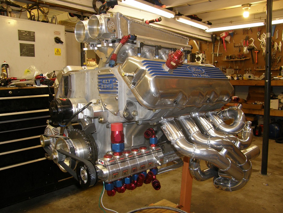
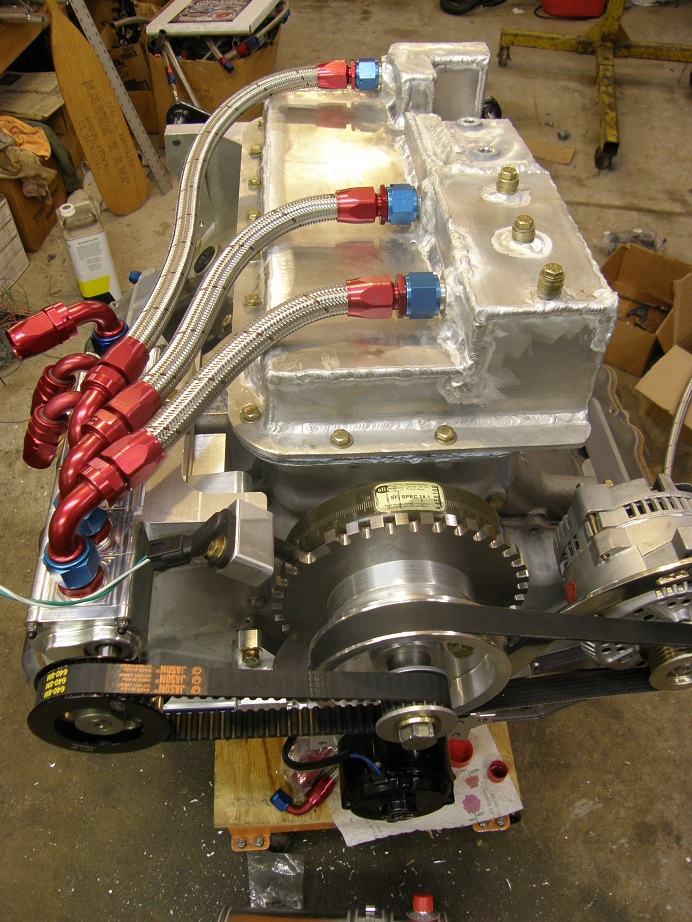
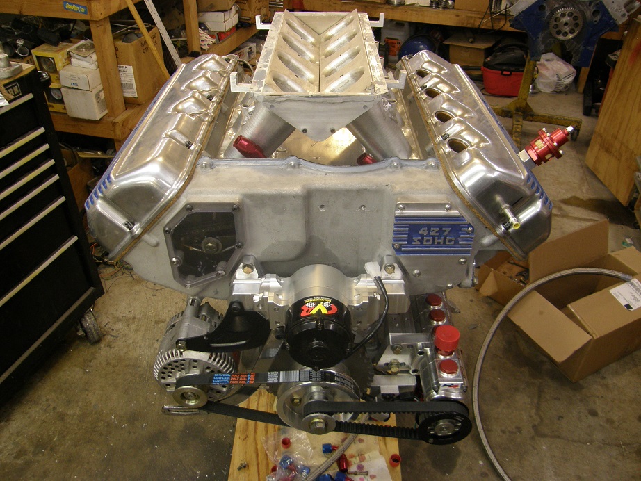
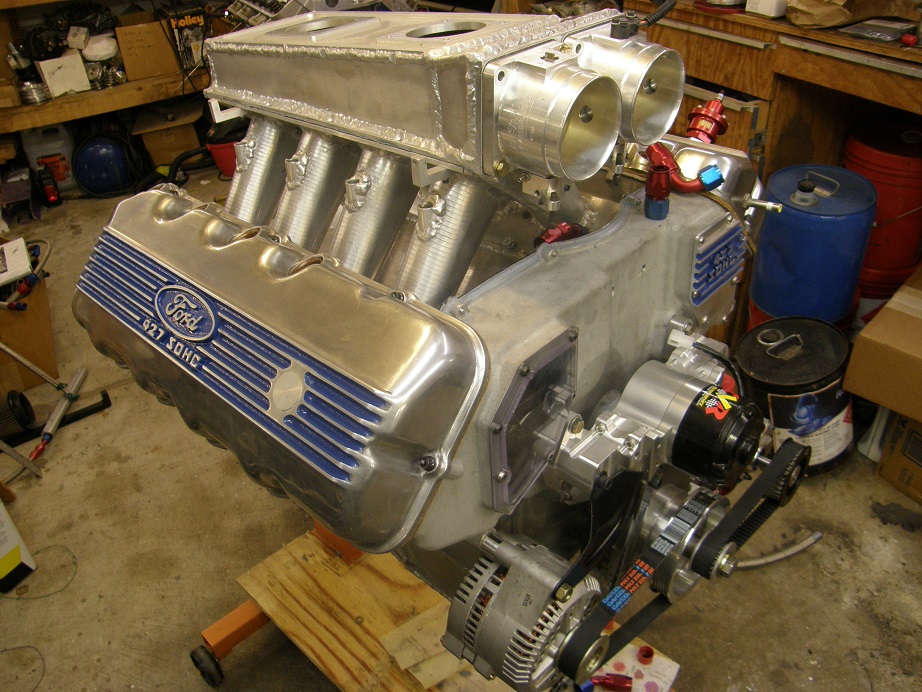
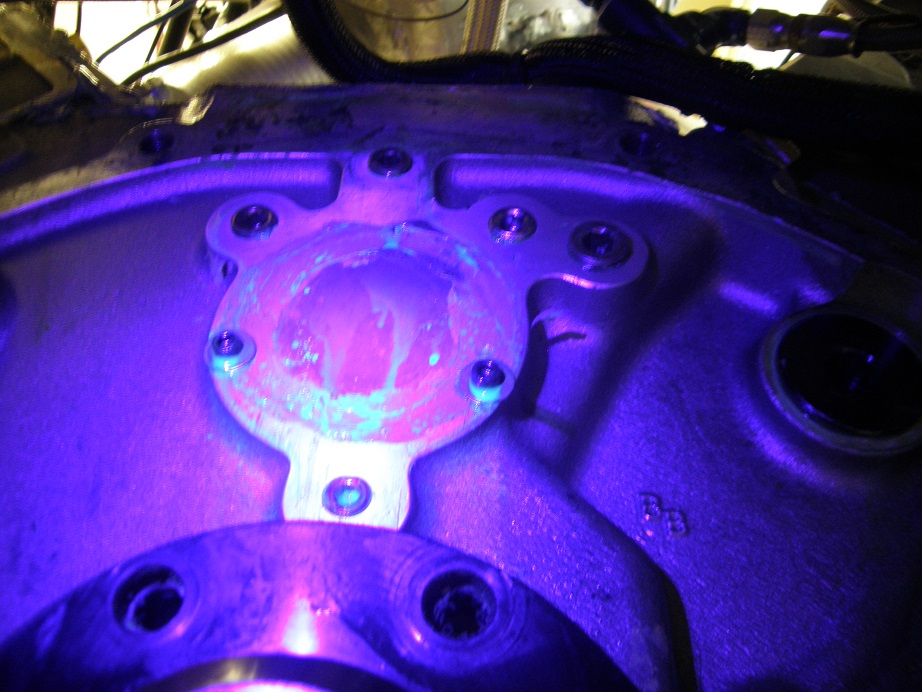
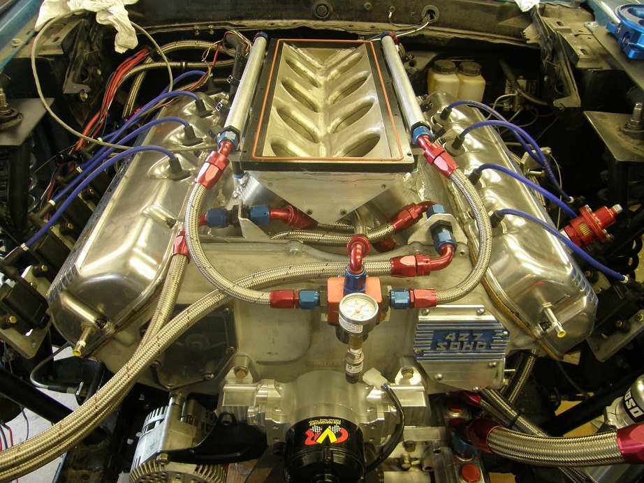
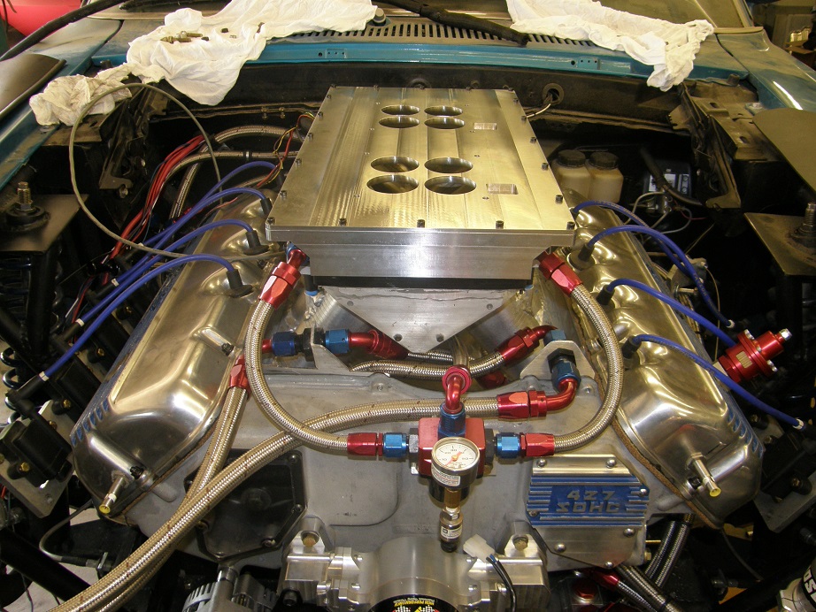
While we were thinking about this, we decided to go ahead and put Scott's 8 O2 sensor setup on the engine. Here's a picture of the engine with this setup installed:

This setup uses the closed loop corrections available in the MS3X to monitor the O2 sensors in each primary pipe, and then hold the injectors open a shorter or longer period of time, to try to hit the targeted A/F ratio in each cylinder. After getting all the O2 sensors installed Scott configured the CAN communications in the software, and we were ready to run. We targeted the A/F at 12.6:1, and ran the pull hoping for a significant power increase. We did see a bump of about 10 HP, but it wasn't a real big improvement. This basically meant that the sheet metal intake I had built for this engine, previously known as "the steaming pile" because of the problems it seemed to give us in 2011, was actually pretty good. In fact, Scott was praising the steaming pile by the end of the day Sunday as one of the better sheet metal intakes he's seen with respect to fuel distribution.
Last time I ran this engine on the dyno, in its 585" form, it had wanted to run a little lean. So we ran another pull, changing the targeted A/F ratio to 13:1, and the engine really picked up, to the tune of about 18 HP. That was good news. We continued to log the cam data, and we continued to see what appeared to be a big retard in the left cam during the pull. It was about the end of the night on Saturday, so we made plans for the next day and called it a night.
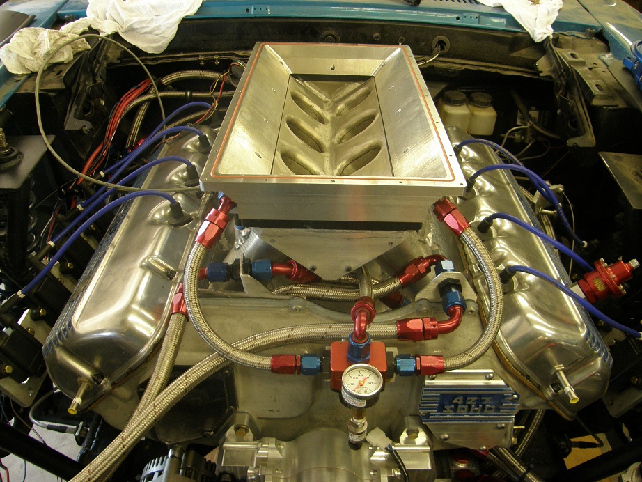
This morning (Sunday), the first thing I did when getting out to the shop was to take my second Hamlin sensor, and install it as an auxiliary cam sensor in the right valve cover. I was certain that the right cam would retard with engine RPM, so if the right and left cams were moving in the same direction, we would have confirmation that both cams were retarding. Thinking about this a little more, I began to suspect that the long, slow pulls I had done on the test engine back in 2006 were not really reflective of what would actually be happening at the track, and that maybe with the rapid logging available using the MS3X, and a normal dyno pull rate of 300 RPM/sec (rather than the 25 or 50 RPM/sec I was using in 2006) might make the cams behave differently. When Scott arrived the first thing we did was run the test to look at the left and right cams together. Sure enough, they were both moving in the same direction, and both retarding a significant amount. Here are four screen shots from the MS3X datalogger that show this effect:
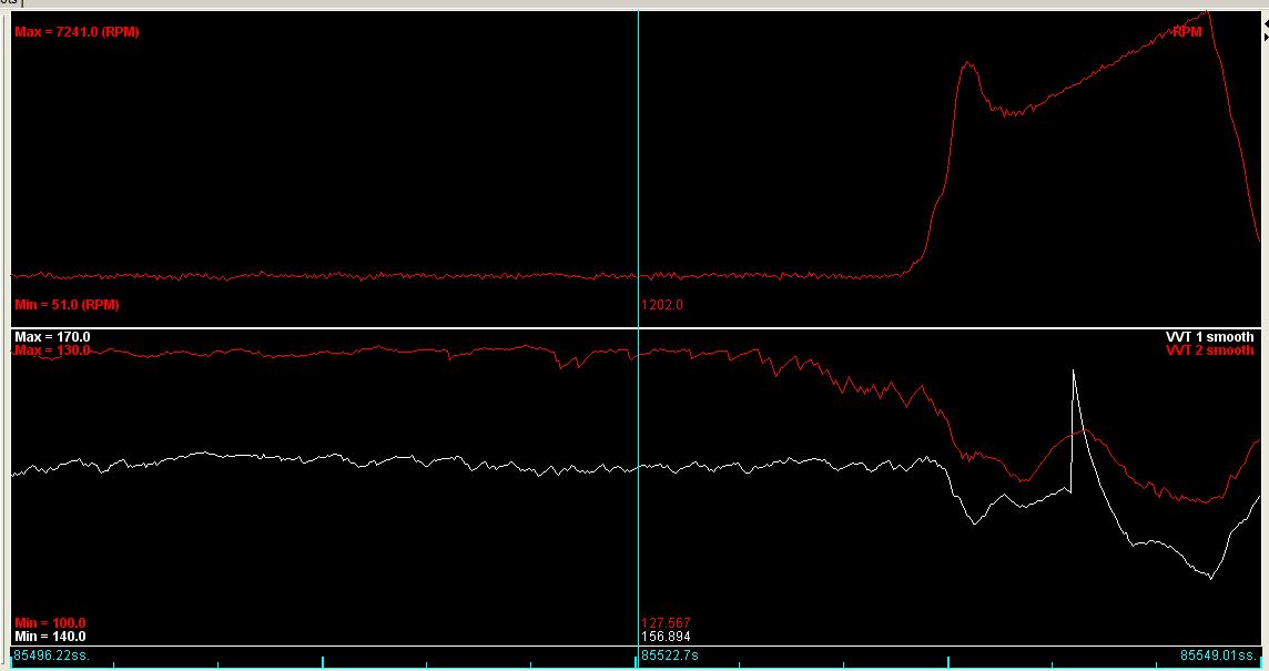
The vertical blue line running through the graph has numbers next to it, and these are the ones we want to pay attention to. The top graph shows engine RPM, which is about 1200 at this point in the log. The bottom graph shows the cam sensor angles. These are phased arbitrarily, so what we are looking for is changes in these numbers, not absolute values. The red line is the right cam sensor, and the white line is the left cam sensor. At this point in the log the right cam is at 127.6 degrees, and the left cam is at 156.9 degrees. Off to the right of the vertical blue line, you can see the engine RPM during the dyno pull. Also, the left cam line goes vertical in the middle of the pull, but that's not real data, that is just a noise spike. Here are the other graphs with the blue line positioned at various points during the pull:
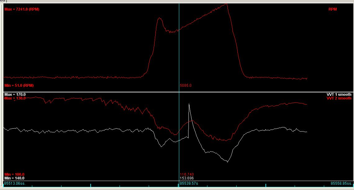
In this graph we are at the start of the pull, 5000 RPM, and the right cam has retarded to 116.7 degrees, while the left cam has retarded to 153.7 degrees. Here's the next graph:
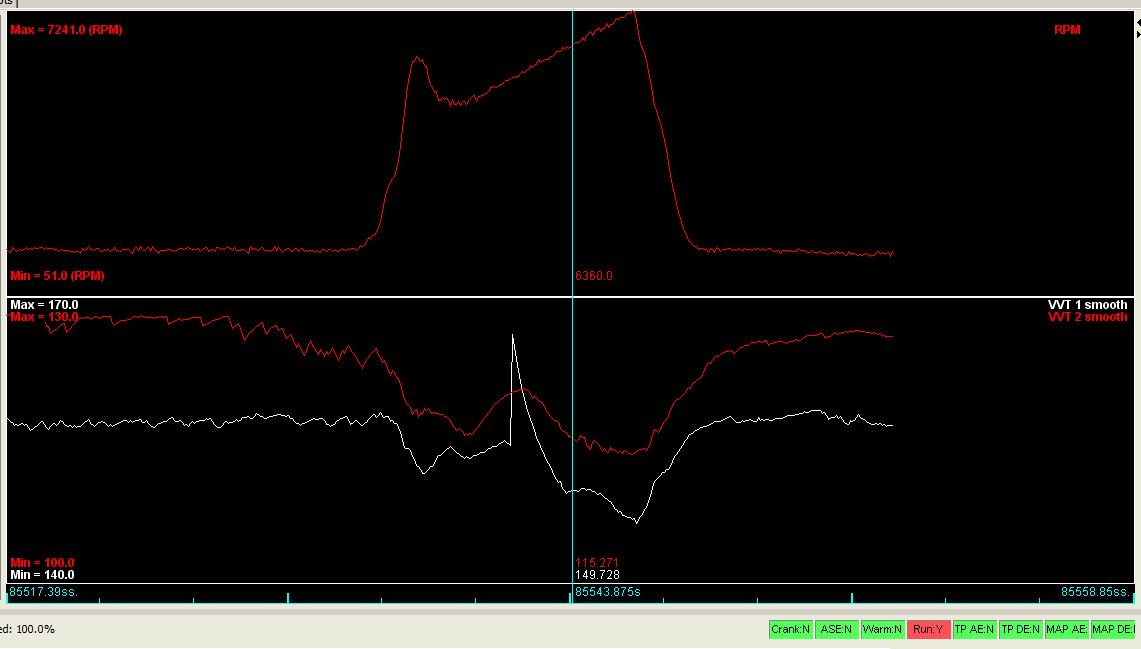
Here we are at 6360 RPM, and the right cam has retarded to 115.3 degees, while the left cam has retarded to 149.7. Here's the next graph:

In this case we are almost at the end of the pull, at 7180 RPM, and the right cam has retarded to 113.7 degrees, while the left cam has retarded to 147.0.
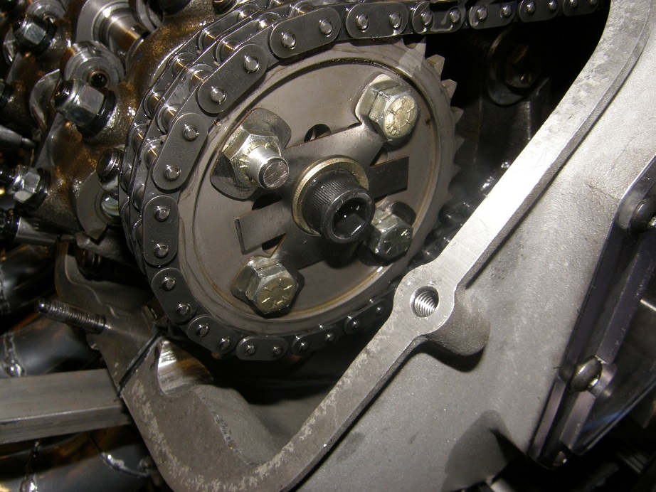
To be honest I'm not really sure I believe these numbers; that is a tremendous amount of chain stretch, and it just seems unreasonable to me. The difference between the right cam at idle (127.6 degrees) and the right cam at 5000 RPM (116.7 degrees) is just not believable. Also, the left cam is retarding more during the pull (6.7 degrees) than the right cam (3.0 degrees). This is in spite of the fact that as the engine spins the length of the chain between the drive sprocket and the left cam is shorter than the length of the chain between the drive sprocket and the right cam, in the direction of engine rotation. If anything, the right cam should be retarding more than the left cam, if indeed they are both retarding as this data seems to suggest. I can see several potential sources of error in this data, including variability in the targets (which are just bolt heads), and frequency response of the Hamlin sensors. Just doing a quick calculation, at 7000 engine RPM the cams are spinning at 3500 RPM. This is 58.33 rotations per second. To discriminate 0.1 degrees of accuracy the update frequency of the sensors must be 1/(58.33 * 3600), or about 210 KHz, which is pretty fast for a magnetic sensor. Even to discriminate 1.0 degrees the frequency response still has to be 21 KHz. I need to do some research on the sensors to see if they are up to the drill here.
In any case more happened on Sunday than I have reported so far; I will update this post tomorrow with more information on Sunday's tests - Jay


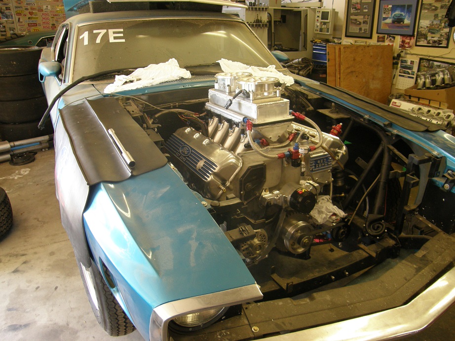
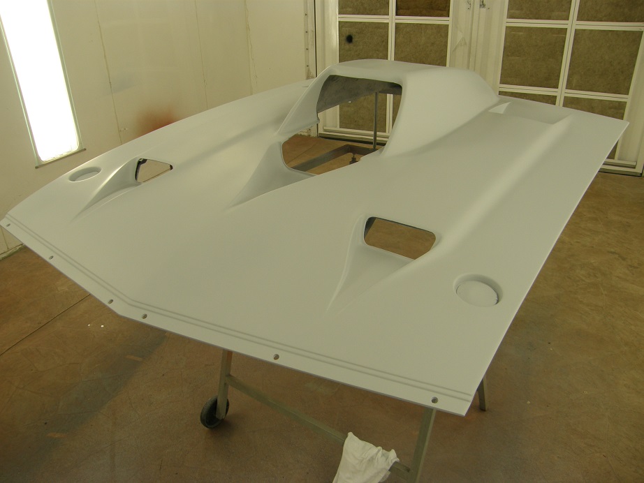
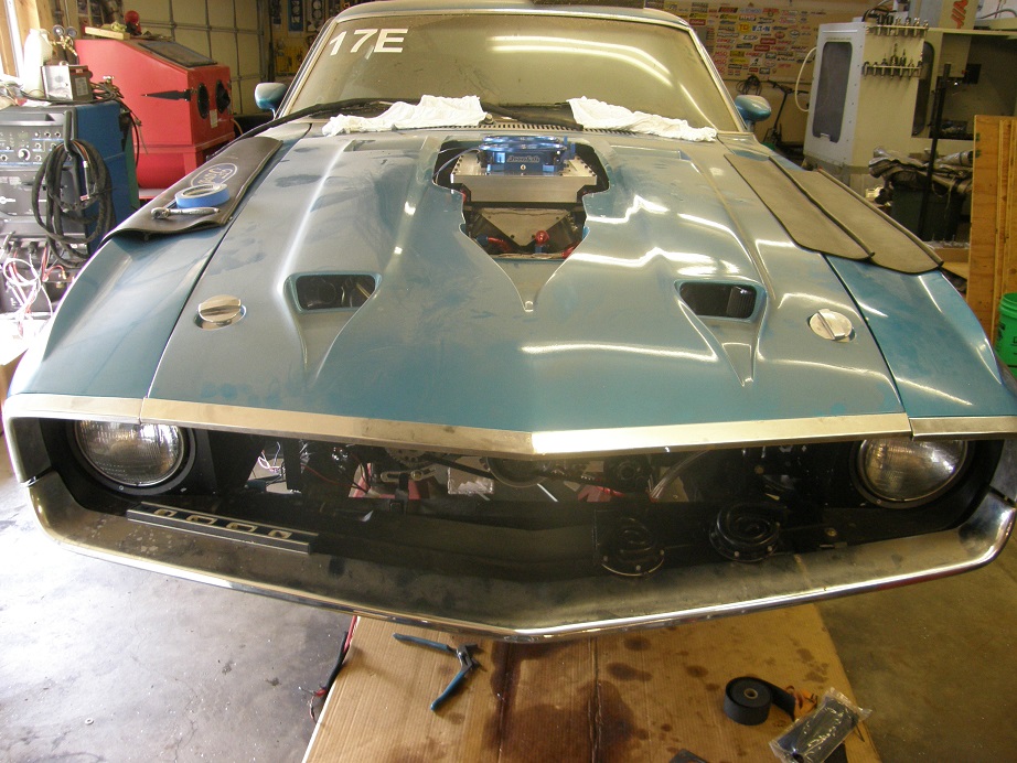
 I will have to either trim the underside of the hood or revamp the throttle linkage; I haven't decided which yet.
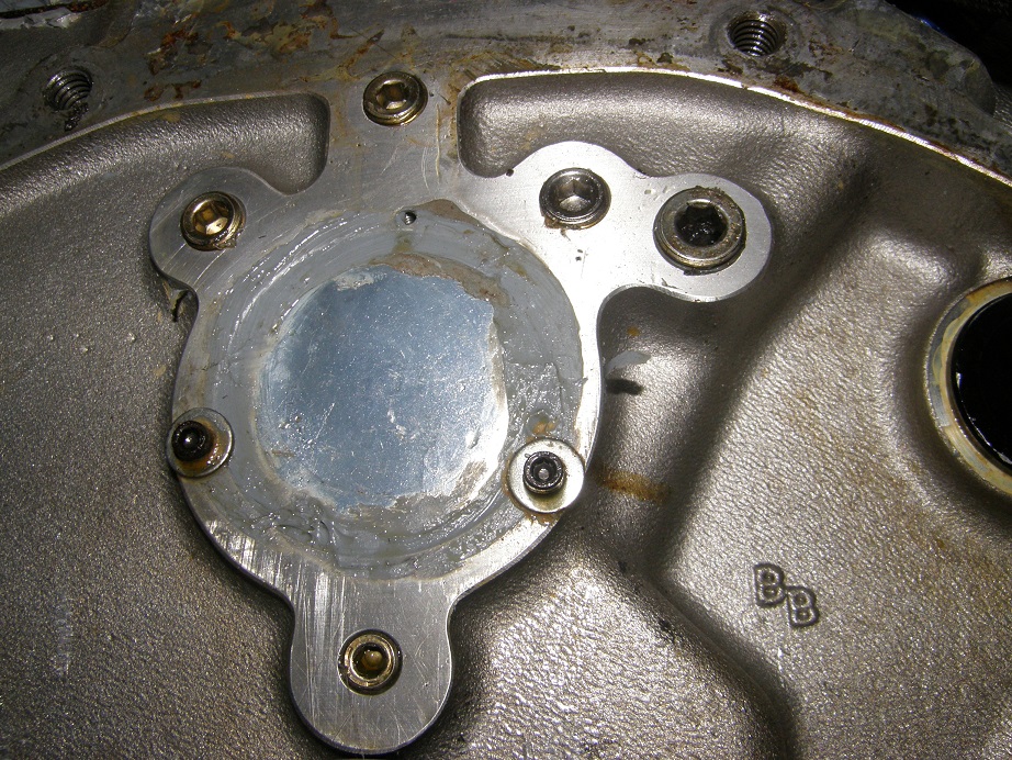


 In six months I'll read this post and be able to think objectively about it, but tonight all I can do is think of various four letter words...
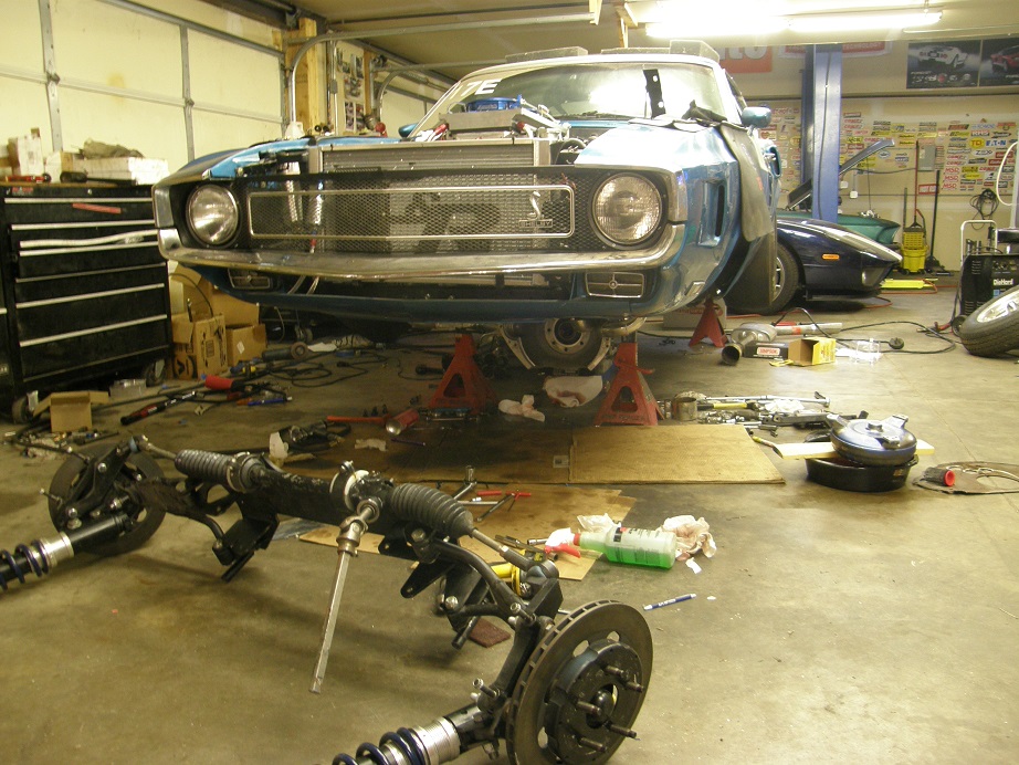
 Anyway, I got most of the way done with the wiring on Saturday night and finished the MS3X wiring up by about noon on Sunday. After a family commitment I was back out in the shop by 3:00; I still had to install the wiring for the O2 sensor controller and a new relay and wiring for the electric water pump. Once finished with that I turned on the power, and happily there was no smoke. After checking out some of the systems everything seemed to be working well except for the Aeromotive fuel pump. It had flipped on once when I was messing with the wiring, and that was it. Finally I gave up on that for a while, and finished up under the car, which involved filling the differential with oil, draining the old transmission fluid, installing the pipes and mufflers, and then installing the rear tires in preparation for breaking in the rear end gears. After that was all done it was around 6:00 PM, and I decided to take the fuel pump and filter arrangement of the dyno and plug it into the car. Once I did this the fuel system started working fine. Filled her up with trans fluid and put water in the radiator, and crossed my fingers as I turned the key. The engine spun over with no trouble, but wouldn't start. I broke down and hooked the computer up to the EFI system, and realized at once when the display came up that I had not recalibrated the throttle position sensor. I did that, and tried again, and this time the car fired right up. Next I wired in the electric fan control, and set up the software to turn the fans on at 180 degrees, and started the engine again. As it warmed up the idle came up higher and higher, and I still have to address that issue. The Accufab throttle bodies have the throttle stop screws loctited in place, and there is no additional screw to set the throttle openings, so I had to try to do that with the linkage. That of course is not the ideal solution, and I'm going to have to work on that in the coming week to find a solution. But after adjusting the throttle linkage a little more I got the engine to settle into a 1500 RPM idle (?), and warmed it up. Everything looked fine, so after it cooled a little I took the following video, where I started up the engine again and put the car in first gear to break in the new rear end gears. The video is not the greatest quality but you will get the idea. You will also see that there is a lot of cleanup and finish work left to do on the car:
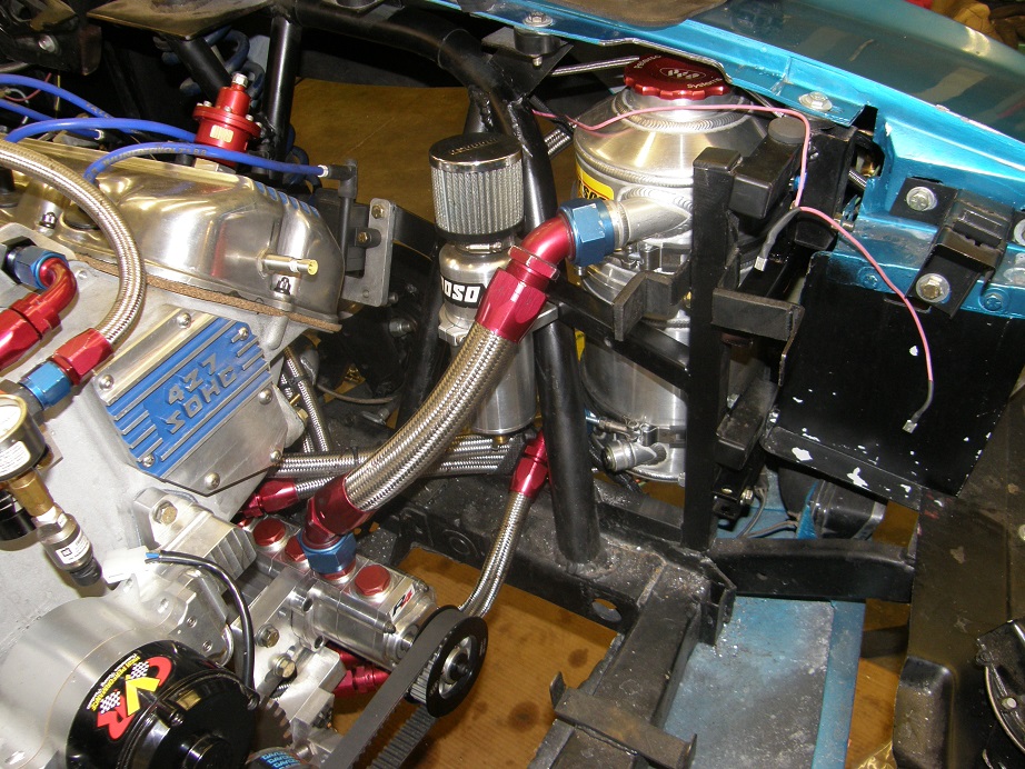

 The aluminum dealer told me I could pick up the material on Friday.