Show Posts

This section allows you to view all posts made by this member. Note that you can only see posts made in areas you currently have access to.


Topics - jayb

Pages: 1 ... 10 11 [12] 13 14 ... 25
166
This board is for posting information on the track results you have for your FE powered vehicle.  I have put a suggested format below, and put a couple of example vehicles on the board to start with.  You can copy the format from this sticky, and paste it into your post, and then fill in the information.  If you don't have all the info (very few people will), don't sweat it, just fill in what you have.  If you have put the engine information into the FE Dyno Results board, please link to it here.  Also please post a picture or two of the car at the track if you have them.  Comments always welcome.  Hopefully this board will turn into a useful repository of drag strip performance.

**********************************************************************************************************

Performance Summary:
      1/4 mile ET:               1/4 mile MPH:
      1/8 mile ET:               1/8 mile MPH:
      60 foot time:
      Track:
      Weather Conditions:

Vehicle Use:
(For example, occasional strip use, street/strip with regular strip use, or strip only)

Vehicle Specifications:

Model Year:

Model:

Style:

Engine Details (link to post in Dyno Results board if available:

Transmission:

Torque converter details (if automatic):

Clutch details (if manual):

Driveshaft:

U-joints:

Rear end type:

Differential type:

Gear Ratio:

Axles:

Front tires:

Front wheels:

Rear tires:

Rear wheels:

Front suspension information:

Rear suspension information:

Ready-to-race vehicle weight, including driver:

167
FE Engine Dyno Results / 511" FE used in Drag Week 2005
« on: May 06, 2015, 08:24:05 AM »
Performance Summary:
      Cubic Inches:    511                  Dyno brand:  SuperFlow 901
      Power Adder:    None           Where dynoed:  R&R Performance
      Peak Horsepower:  706
      Peak Torque:   636

Horsepower and Torque Curves:

Note on the graph below:  This shows the dyno results before and after a spring change, from Comp 919 springs to Comp 943 springs.  The 919 springs were the ones recommended by Comp.  Moral of the story - the recommended valve springs from the manufacturer may not work, if you are not running a small block Chevrolet  ;)


Engine Specifications:
  Block brand, material, finished bore size, other notes:
Shelby aluminum block, 4.375" bore     

  Crankshaft brand, cast or forged, stroke, journal size:
Scat billet 4.25" stroke crank, 2.200" rod journals (BBC size)
     
   Connecting Rods brand, material, center to center distance, end sizes, bolts:
Crower billet 6.800" center to center BBC Rods, .990 pin

   Piston brand, material (caster, hypereutectic or forged), dish/dome volume, static CR:
Diamond custom forged 11.75:1 pistons with tool steel pins and double spiro-locks

  Main Bearings, Rod Bearings, Cam Bearings brand and size:
Federal Mogul main bearings, standard, Clevite 77 rod bearings, standard

   Piston rings brand, size, other notes:
Total Seal conventional, file fit rings (not gapless), plasma moly top ring, 1/16 - 1/16 - 3/16

   Oil Pump, pickup, and drive:
Precision Oil Pumps high volume oil pump with the spacer added to the relief valve spring (70-80 psi hot oil pressure), and the 5/16" hex shaft drive

   Oil pan, windage tray, oil filter adapter:
Cobra aluminum oil pan, Canton pickup, Ford windage tray, Ford large passage oil filter adapter

   Camshaft brand, type (hyd/solid, flat tappet or roller), lift and duration (adv and @.050")
Comp Cams custom solid roller cam, Xtreme Energy street roller series, Lobe # 4878 on the intake, # 4879 on the exhaust; adv duration 304/310, duration @ .050" is 266/272, lift is .700"/.710", lobe separation angle is 110 degrees

   Lifters brand, type:
Comp Cams mechanical roller lifters with oiling to the needle bearings

  Timing chain and timing cover:
Rollmaster timing chain set (from Precision Oil Pumps), roller thrust bearing, Shelby timing cover

  Cylinder heads brand, material, port and chamber information:
Edelbrock heads, 2.25"/1.75" SS valves, 11/32" stems, heads ported and milled to 68cc chambers, rocker stud helicoils replaced with EZ Locks for strength, oil return holes chamfered and drilled out, the head bolt hole where the oil flows to the head also drilled out for clearance between the stud and the hole to allow the oil to flow, oil to rockers restricted with .070" orifice

   Cylinder head flow in cfm at inches of lift (28" H2O pressure drop):
      Intake               Exhaust
      .100      80           .100     62
      .200     169          .200    118
      .300     233          .300    166
      .400     280          .400    203
      .500     308          .500    236
      .600     329          .600    252
      .700     343          .700    261
      .800     351          .800    267

  Flow bench used, location:
SuperFlow SF600 bench, R&R Performance

   Intake valve brand, head size, stem size:
Manley 2.25", 11/32 stem

   Exhaust valve brand, head size, stem size:
Manley 1.75", 11/32 stem
   
   Valve springs brand, part number, specs:
Comp 943, 240# on the seat, 600# open

   Retainers and locks brand, part number, specs:
Comp Cams titanium retainers, spring seats, and 10 degree locks

   Rocker arm brand, type (adjustable or non-adj), material, ratio
Erson roller rocker assembly

   Rocker shafts and stands, brand, material:
Erson roller rocker assembly

   Pushrods brand, type, length:
Smith Brothers 3/8" pushrods, 9.200" OAL

  Valve covers, brand, type:
Factory Ford CJ valve covers, polished

   Distributor brand, advance curve information:
MSD billet aluminum FE distributor, 18 degrees advance in the distributor, in by 3400 RPM

   Harmonic balancer brand:
ATI 7 pound SFI certified harmonic balancer

   Water pump brand, type (mechanical or electric):
Edelbrock aluminum water pump, mechanical

   Intake manifold brand, material, porting information:
Edelbrock Victor intake, heavily ported with re-sleeved pushrod holes, top milled at an angle so that the carb is at the same angle as the stock intake (for use with the shaker), front breather hole bored, extra milling and slotting on the intake port face done for better oil drainback

   Carburetor(s) brand, type
Holley 1150 cfm Dominator carb, stock jets

  Exhaust manifolds or headers brand, type:
Hooker 2 1/8" primary adjustable race headers, modified for ground clearance in car (no longer equal length primaries)

168
Performance Summary:
      Cubic Inches:   492            Dyno brand:  SuperFlow 901
      Power Adder:   No            Where dynoed:  FE Power LLC
      Peak Horsepower:  662.0
      Peak Torque:  623.7

Horsepower and Torque Curves:


Engine Specifications:
   Block brand, material, finished bore size, other notes:
Ford 427 sideoiler block, 1968, cast iron, 4.293 (0.060" over), cracks welded up on deck and in main cap bolt holes, thin cylinders
   
   Crankshaft brand, cast or forged, stroke, journal size:
Scat 4.25" cast iron stroker crank, BBC rod journals

   Connecting Rods brand, material, center to center distance, end sizes, bolts:
Scat 6.700" center to center H-Beam BBC connecting rods, .990" BBC pins, 2.200" rod journal size 2.200", Scat rod bolts

   Piston brand, material (caster, hypereutectic or forged), dish/dome volume, static CR:
Custom forged Diamond pistons and pins, 16cc dish, static compression ratio 11.3:1

   Main Bearings, Rod Bearings, Cam Bearings brand and size:
Federal Mogul 125M main bearings, Federal Mogul Z87200CH rod bearings

   Piston rings brand, size, other notes:
Total Seal 1/16 - 1/16 - 3/16 p/n CR7190-65 plasma moly

  Oil Pump, pickup, and drive:
Precision Oil Pumps blueprinted high volume, 5/16" drive

   Oil pan, windage tray, oil filter adapter:
Milodon 7 quart p/n 31130 pan, Moroso p/n 22940 windage tray, Ford stock late model, high flow filter adapter

   Camshaft brand, type (hyd/solid, flat tappet or roller), lift and duration (adv and @.050")
Comp Cams custom roller, intake lobe 4878, exhaust lobe 4879
- Lift .700 intake / .711 exhaust
- Advertised duration 304 intake / 310 exhaust
- Duration at .050" lobe lift 266 intake / 272 exhaust
- Lobe separation angle 110
- Installed 4 degrees advanced, ICL=106 ATDC

  Lifters brand, type:
Crower solid roller with HIPPO pin oiling feature, p/n 62216H-16

   Timing chain and timing cover:
Rollmaster Indexable Tru-Roller timing set, Shelby timing cover

   Cylinder heads brand, material, port and chamber information:
Edelbrock Aluminum 60059 bare castings
- Guides installed for 11/32" stem valves
- Max effort porting job
- 72cc combustion chambers
- .070" restrictors in head oiling passage

   Cylinder head flow in cfm at inches of lift (28" H2O pressure drop):
      Intake               Exhaust
      .100   80              .100    62
      .200   169            .200    118
      .300   233            .300    166
      .400   280            .400    203
      .500   308            .500    236
      .600   329            .600    252
      .700   343            .700    261
      .800               .800

   Flow bench used, location:
Superflow SF-600, R&R Performance

   Intake valve brand, head size, stem size:
Manley stainless steel 2.250" head, 11/32" stem

   Exhaust valve brand, head size, stem size:
Manley stainless steel 1.750" head, 11/32" stem
 
  Valve springs brand, part number, specs:
Comp Cams p/n 943, 240# on seat, 650# full open

  Retainers and locks brand, part number, specs:
Comp Cams titanium retainers, 10 degree, p/n 731-16, Comp Cams machined steel locks, p/n 611-16

  Rocker arm brand, type (adjustable or non-adj), material, ratio
Erson rocker assembly, adjustable, aluminum with roller bearings, 1.76:1

  Rocker shafts and stands, brand, material:
Erson rocker assembly

   Pushrods brand, type, length:
Smith Brothers ball and cup, .375" diameter, 9.200" overall length

  Valve covers, brand, type:
Cobra Lemans aluminum valve covers from Summit Racing

   Distributor brand, advance curve information:
MSD electronic distributor, p/n 8594
- Recurved for 20 degrees total centrifugal advance
- All advance in by 3000 RPM

   Harmonic balancer brand:
ATI steel p/n 918310, SFI approved

   Water pump brand, type (mechanical or electric):
Edelbrock aluminum p/n 8805, mechanical

  Intake manifold brand, material, porting information:
PSE intake adapter, port matched to the heads, with Weiand tunnel Ram

   Carburetor(s) brand, type
2 Holley 660 Center Squirter carbs

   Exhaust manifolds or headers brand, type:
Hooker adjustable race headers, 2 1/8" primaries, p/n 6375HKR

169
FE Engine Dyno Results / FE Dyno Results and Engine Information
« on: May 05, 2015, 02:45:12 PM »
This board is for posting information on the dyno results you have for your FE engine.  I have put a suggested format below, and put a couple of example engines on the board to start with.  You can copy the format from this sticky, and paste it into your post, and then fill in the information.  If you don't have all the info (very few people will), don't sweat it, just fill in what you have.  If you have a photo of the engine, either on or off the dyno, please post that also.  Comments always welcome.  Hopefully this board will turn into a useful repository of FE engine data.

**********************************************************************************************************

Performance Summary:
      Cubic Inches:               Dyno brand:
      Power Adder:               Where dynoed:
      Peak Horsepower:
      Peak Torque:

Horsepower and Torque Curves:


Engine Specifications:
   Block brand, material, finished bore size, other notes:
      
   Crankshaft brand, cast or forged, stroke, journal size:
      
   Connecting Rods brand, material, center to center distance, end sizes, bolts:

   Piston brand, material (caster, hypereutectic or forged), dish/dome volume, static CR:

   Main Bearings, Rod Bearings, Cam Bearings brand and size:

   Piston rings brand, size, other notes:

   Oil Pump, pickup, and drive:

   Oil pan, windage tray, oil filter adapter:

   Camshaft brand, type (hyd/solid, flat tappet or roller), lift and duration (adv and @.050")

   Lifters brand, type:

   Timing chain and timing cover:

   Cylinder heads brand, material, port and chamber information:

   Cylinder head flow in cfm at inches of lift (28" H2O pressure drop):
      Intake               Exhaust
      .100               .100
      .200               .200
      .300               .300
      .400               .400
      .500               .500
      .600               .600
      .700               .700
      .800               .800

   Flow bench used, location:

   Intake valve brand, head size, stem size:

   Exhaust valve brand, head size, stem size:
   
   Valve springs brand, part number, specs:

   Retainers and locks brand, part number, specs:

   Rocker arm brand, type (adjustable or non-adj), material, ratio

   Rocker shafts and stands, brand, material:

   Pushrods brand, type, length:

   Valve covers, brand, type:

   Distributor brand, advance curve information:

   Harmonic balancer brand:

   Water pump brand, type (mechanical or electric):

   Intake manifold brand, material, porting information:

   Carburetor(s) brand, type

   Exhaust manifolds or headers brand, type:


170
FE Technical Forum / Dyno Results and ET Results Stickies?
« on: April 30, 2015, 10:56:16 AM »
I was on the FE Forum a little earlier today, and saw a suggestion for a sticky on that board that kept a list of cars and ETs run with FE engines.  It will never happen over there, but I could easily do one here.  I'm a little reluctant to post sticky topics, because they tend to multiply and take up the first several slots of the message board, but I guess adding two, one for each of these topics, wouldn't be too bad.  What do you guys think, should I do this?

172
FE Technical Forum / TFS EFI Manifolds for the intake adapter
« on: April 13, 2015, 07:51:34 PM »
Joe Craine got me all excited today when he sent me a bunch of pictures of a couple of Trick Flow Specialties EFI manifolds sitting on top of his intake adapter.  I think this would be an awesome setup, both from an appearance and performance standpoint, and would give anybody an easy entry into an EFI system.  I've posted some of the pictures that Joe sent below, with some explanatory notes. 

The photos below shows the front of the TFS intake marked for cutting, to fit the intake adapter, and then the cut version sitting in place. 


Here's the back of the intake, which doesn't appear to need any trimming at all:


Here's a picture of the runners, with the top of the intake removed; pretty nice shot to the ports:


Here's a picture of the manifold with one of the tops in place; this is the normal street top, with some additional runner length built in:


Here's the bottom half of the race style top in the next picture, which gives shorter runners and a straighter shot to lower manifold, and then both halves installed in the following picture, with the other top sitting off to the side:


The remaining pictures show the manifold options mounted on an engine, along with some measurements from the top rail of the block. 


Joe tells me that you can buy ready made fuel rails for these manifolds, and of course you can bolt on the correct size throttle body.  Add injectors and an EFI box, and you have a nearly complete EFI system.  I'm impressed...

173
FE Technical Forum / 427 Build for '67 Galaxie
« on: April 11, 2015, 07:58:23 AM »
I got the email below from a guy who wants to build a 427 for a 67 Galaxie.  I'm going to encourage him to join the forum, but for now I thought I'd post his questions here and let him see some opinions, mine included - Jay

Hello, I'm a Ford Fe fan. I built a mild 390 because I couldn't afford to any mods to my 66 Ford truck and knew an Fe block would drop right in. I did that about 10 years ago and she's been been doing ever since, knock on wood. Been a fan of the on demand torque ever since. My next project looks to be a 2 door 67 Ford Galaxie. I want to build a 427 for it. I searched around found that it's very popular to stroke them out. But, that's not what I want to do. I'm asking for some recommendations on a few things, please. I've a few questions. First, let me start with my goal in mind for the engine build/car usage. I want the car to be a fun weekend toy that'll be dependable, sound good, and have good driveability and possibly make some short road trips and not be too wild or extreme for a toy. Neighborhood of 450 hp is what I'm shooting for. Maybe a trip to the drag strip will happen. It'll have power steering, a/c, and have a 4 speed toploader with 3:73 gears in the rear. I was looking at the compression about 10:1 to just run pump gas. MSD 6AL ignition with an MSD street billet distributor. I think I'll contact Cam Research for a custom ground to match my preference, and 750ish carb. I want to stay close to stock dimensions as close a possible, just a little more power than factory rated. I found that the 4.25 bore is real common with the choice of pistons available. I'm fine with that because that doesn't stray very far from what I want. I just don't want the 4.25 stroke with the 6.700 inch rod to make it a 482 C.I.D. I've heard that the 482 is actually easier on the cylinder walls because the rod angularity isn't as harsh as the 427. Scat makes a complete and balanced 427 rotating assy. I'm also aware that the cam profile will play a big part. But, I can specify to keep that not too aggressive. My questions are:
 
1. Is that true about the cylinder wall pressure?
 
2. I would like to use Edelbrock (more in my price range) heads and don't intend to change the valve sizes to a bigger size. Jegs part number: 350-60079. Will leaving them alone and not porting them keep it tame enough for my preference? Or, will porting them be a better option on the 427?
 
3. If a 482 is a better option because of the cylinder wall pressure, then will leaving the heads as is be best to not get too wild?

174
FE Technical Forum / Prototype Adjustable timing chain set
« on: March 15, 2015, 10:28:16 PM »
The pictures below are the top gear of a new adjustable timing chain set, being developed by Survival Motorsports.  At the PRI show Barry and I hounded Cloyes about doing something like this for the FE (Cloyes makes these already for other engines), in light of the availability of my two piece timing cover.  But Cloyes has been kind of moving slow, so Barry has been taking matters into his own hands.  Just to give them the basic idea and a prototype product, he has taken two of the top gears from one of the Cloyes premium sets, and machined them to make a single, adjustable top gear.  This is really going to be a cool product:


There is a +/- 10 degree range of adjustment on this gear, and it will come with the premium roller chain, making it a top end setup.  I'm not privy to all the arrangements Barry has with Cloyes, but my guess is that if they don't make this available soon, Barry will probably manufacture them himself. 

I can't wait to try one of these out on the next engine...

175
Since the previous post on this topic ( http://fepower.net/simplemachinesforum/index.php?topic=2402.0  ), I've been doing a lot of research on sheet metal style intakes.  Based on the poll in the previous thread, it appeared that this type of intake was of the highest interest, and without a good alternative available for the FE (except for my intake adapter + the 351C tunnel ram), I thought it would be best to pursue this manifold option first.

My original plan had been to do a design that could be cast in aluminum to minimize cost for the manifold.  However, a couple things changed my mind about that.  First, after digging pretty deep into sheet metal intake design, it became clear that one design would definitely not fit all.  I suppose that's why the sheet metal intake companies like Hogan are in business; depending on your RPM range and the duration of your camshaft, the ideal intake will vary quite a bit in runner length, plenum volume, runner taper, etc.  Tooling up a casting was going to be expensive, and I couldn't really afford to tool up several of them to meet a variety of different requirements.  Second, working with the foundries has been very frustrating in terms of delivery time.  I'm a pretty small fish to these companys, not part of the customer base that keeps them in business, and I've had to tolerate some significant delays in delivery of my parts, because I don't get a lot of priority. This has led to delays in making my intake adapters available, which is frustrating for me, and also for the people on the list to receive them.

So, I got to thinking - What if I just machined the manifold from billet?  It would be more expensive that way, but there would be no big tooling costs to bear, and no minimum production run required to justify the tooling expense.  Plus I could do several variations of the manifold by just changing the design and machining different parts out of billet.  And I wouldn't be subject to any foundry delays, because billet aluminum in the sizes I was looking at is readily available locally.

One thing that helped move me along in this direction was availability of some parts from Holley that could be adapted to this project.  Holley makes an intake manifold for the LS engine with several different upper plenum types available.  The manifold base contains the lower part of the plenum, and they offer several upper plenums, to mount carbs or throttle bodies depending on the application.  Here are some pictures of what Holley makes available.  First, a picture of the manifold base:


Next, here are three of the upper plenums that are available.  There is also a fourth upper plenum available that is blank, and can be machined for a custom application:


Finally, they make this spacer available, allowing you to increase plenum volume by adding spacers between the manifold base and the upper plenums:


The upper plenums and spacers seal to the manifold base with a big O-ring, kind of like I seal the center plate of my intake adapter to the adapter itself.  So, you can bolt together whatever plenum you want, and change plenum volume for your application by adding spacers.

I got going in January working with Solidworks, and after going through a book full of tutorials I started to design the parts for this project.  I've completed a carbureted and fuel injected version of the first manifold so far.  The runner length is designed to tune at 6800 RPM using the third harmonic, with a power band from 6400 to 7300.  Here's a couple screen captures of the manifold from the Solidworks design file:


All 8 runners are machined individually using this approach.  There are four distinct runners, duplicated on  both sides of the manifold.  They bolt to the lower plenum, using O-rings for sealing.  The lower plenum is designed to accept the upper plenums available from Holley.  The runners also have O-ring grooves in the bottom, to seal to the intake adapter:


Notice that on the inboard sides and tops of the runners, there is a lot of room between the O-ring groove and the machined port.  This is to allow for some porting if desired.  Usually when you increase the size of the FE port, you make it wider on the inboard side to straighten it, and raise it at the top for a better shot at the valve.  The runners are designed to allow porting in this direction, and there is extra meat in the runners all the way to the top for this.

The screen shot below shows the manifold from the front.  You can see that the runners come out of the intake adapter at a bit of an angle. 


The reason for this is that if they came straight out, the runner length would be shorter, and the RPM that this manifold would tune at would go up quite a bit.  To make this a smooth intake tract, I have designed the ports in the intake adapter to swoop upward a little bit, allowing a smooth transition to the stock FE port.

Here's the same manifold, but with runners that include a boss for a fuel injector:


One downside to the fuel injector version of this design is that you have to start with a larger chunk of billet aluminum to machine it.  I can get the standard runners fit into a 3" X 4" cross section, but after adding the fuel injector boss I have to go to a 4" X 4" billet, which is quite a bit more expensive.  So, the EFI versions will be more expensive than the carbureted version of this intake manifold.

Of course I didn't start from scratch with this design, I had to make it fit on the intake adapter first.  When I first got going on the intake adapter project, I had no experience with Solidworks, so I had another guy do the design for me.  It took forever and cost a bunch, and then the pattern shop had to redo it before it was acceptable for generating the tooling, but finally I got a model that worked.  I took this model, removed the FE to 351C ports, and put in some different porting to fit this manifold, then designed the runners and lower plenum from there.  After I got done with that I drew up one version of the Holley plenum top, plus an MSD distributor and a couple of Holley 4150 carbs.  The carbs are not very accurate, except for placement of the throttle bores and mounting holes, but I wanted to get an idea of what the whole induction system would look like.  Here's a few screen shots:


In the last shot, you can see the vertical bolt holes in the front of the runners.  There is a matching hole on the opposite side of each runner, so that two bolts hold each runner in position on the intake adapter.  The other four holes in the bottom of each runner are only used to hold the runner during the machining operations. I wanted to use a vertical bolt to hold the manifold to the intake adapter, because the O-rings will stand a little proud of the mating surface, and trying to put a bolt in at an angle might be problematic.  Using the vertical bolts will allow the manifold to pull straight down onto the intake adapter, and compress the O-rings evenly.

Next I decided to do an EFI version, so I did models of the fuel rails, fuel injectors, and fuel rail brackets.  I put the front facing upper plenum on this one; here's a screen shot:


I don't think this one will fit under the hood, but I'm planning another version that uses shorter runners (and no upward curve in the intake adapter) to tune to the fourth harmonic at 6800 RPM, rather than the third harmonic.  As I understand it, the fourth harmonic will not yield the same high torque as the third harmonic does, but the tuning range is a little wider, maybe 1400 RPM instead of around 1000 RPM.  The objective here would be to get the overall height low enough so that it would fit under a stock hood. 

I'm also looking at doing a version with shorter runners that tunes at the third harmonic, around 8000 RPM.  Maybe the Super Stock guys would like that one.

Finally, I'm also thinking of a version that would bolt onto the existing 13001 intake adapters, with the 351C 4V ports.  The adapter would have to be drilled and tapped for the vertical mounting holes to mount the intake manifold, and this version would not get rid of the angle in the #1, #4, #5, and #8 ports that you get from adapting the FE to a Cleveland intake, but I think it would work as well or better than the Weiand tunnel ram.  And it would look cooler  ;D

When designing these parts I had to figure out how I was going to fixture them and machine them, and without going into any detail, I think I have that figured out.  I should be able to machine all four runners for one side at the same time, using two different setups on my fourth axis CNC machine table.  Keeping the number of setups down lowers the time I have to spend working on the parts, and so reduces the costs.

Speaking of costs, the billet aluminum required for the carbureted version of the intake is around $480.  Add in the cost of the O-rings and the hardware and you are pretty close to $500.  I think I can machine them for another $500, so selling price would be about $1000.  But you have to consider that you will need an intake adapter ($549), plus an upper plenum ($160), and Holley doesn't give the plenum spacers away either ($110).  For the EFI version you would have more material cost, adding probably $125 to the price.  Plus I would probably offer machined fuel rails and fuel rail brackets for another couple hundred bucks, to make the whole package easier to install.

So, my question, and the reason for the post, is this:  Is this too expensive to be attractive?  It would certainly be a lot cheaper than a Hogan manifold, but its still not cheap.  I appreciate any responses to this post, especially if you might be interested in one of these setups, if/when I make them available.  Thanks, Jay

176
FE Technical Forum / 390 Stroker on the Dyno
« on: March 01, 2015, 11:25:28 AM »
Over the past year I've been helping some friends of mine with a father-son FE project.  We finally got it on the dyno this weekend, with pretty good results.  It was a typical dyno session, with unanticipated problems that had to be solved, disappointing results at first, and then happiness all around when we finally got the engine working right.  Its been a while since I posted one of these blow-by-blow accounts, and there's always something to learn from this stuff, so I thought I would detail it all here.

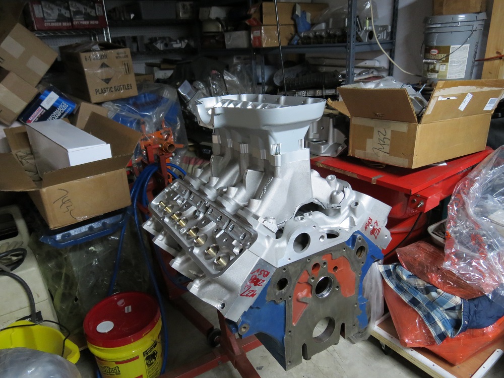
First, here are some specifications on the engine.  It is based on a 0.060" over 391 truck block, and has one of the standard 4.25" stroker kits installed, for 451 cubic inches.  The kit uses a Scat crank and rods, and forged pistons whose manufacturer I don't know.  Compression ratio is 11:1, and we wanted the engine to run on pump gas, so a fairly large cam was selected.  We picked a Comp solid roller, with lobes from their High Energy Street Roller series, #4220 on the intake and #4221 on the exhaust.  Lift and duration on the intake is 255@.050" with 0.650" lift, and 262@.050" with 0.650" lift on the exhaust.  Advertised duration is 300/308, and the cam is ground with a 112 lobe separation angle, and degreed at 108.  We chose Comp 943 springs to use with this cam.  Also, a Harlan Sharp roller rocker setup was used, with their rockers shafts, stands, and solid spacers.

The heads are the normal Edelbrock 428CJ heads, and they are essentially stock; no significant porting work was done, and although there is no flow data available for them, I'd be surprised if they flowed more than 270 cfm on the intake.  They use the stock Cobra Jet sized valves.  The heads are definitely a bottleneck in this combination, and if there had been more money available for the build I think it would have been well spent on a street/strip porting job, to get the intake flow up to 300+cfm.  But that can always be done later...

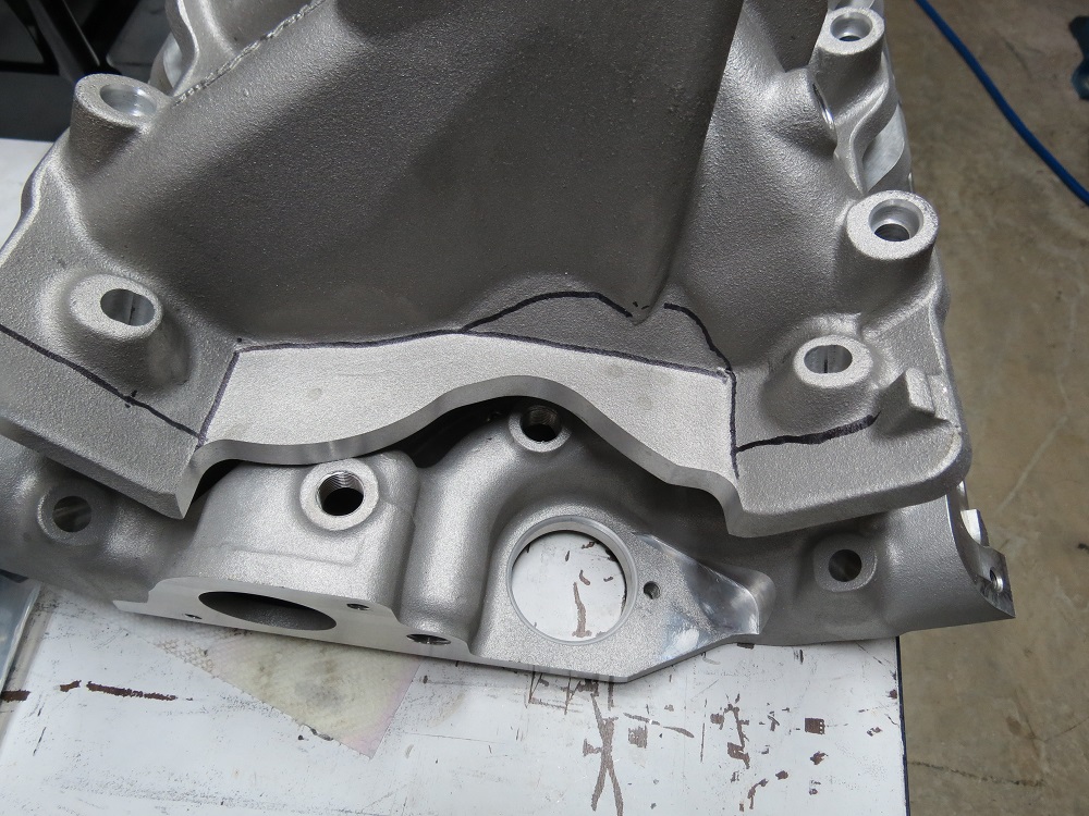
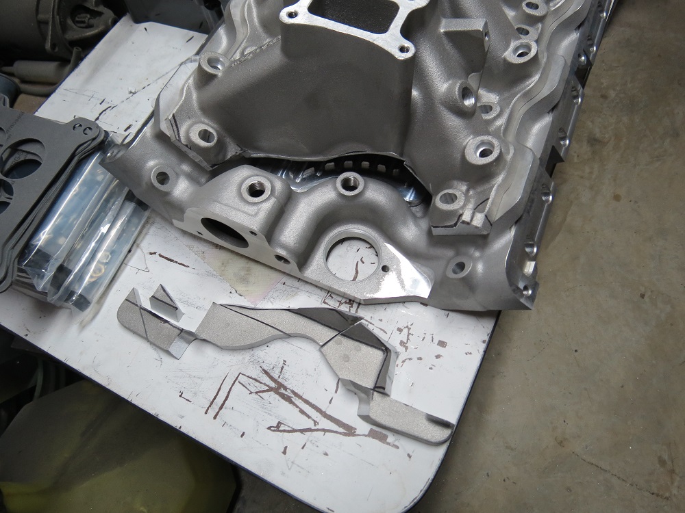
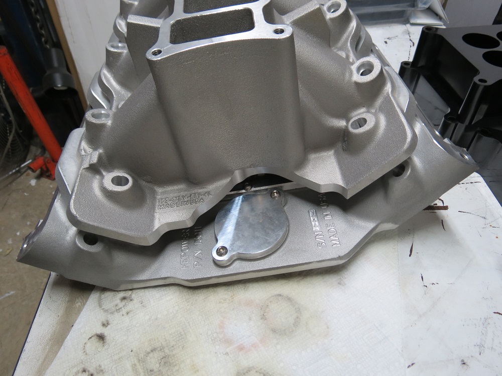
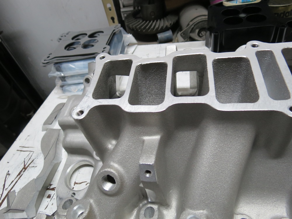
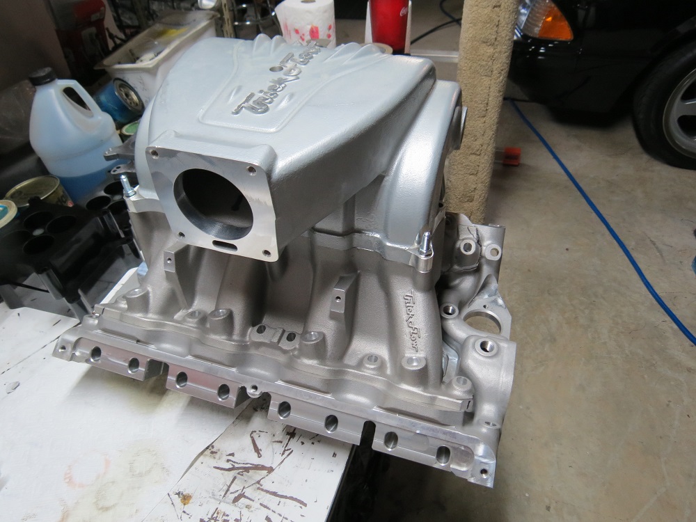
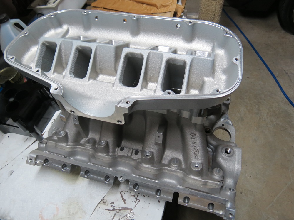
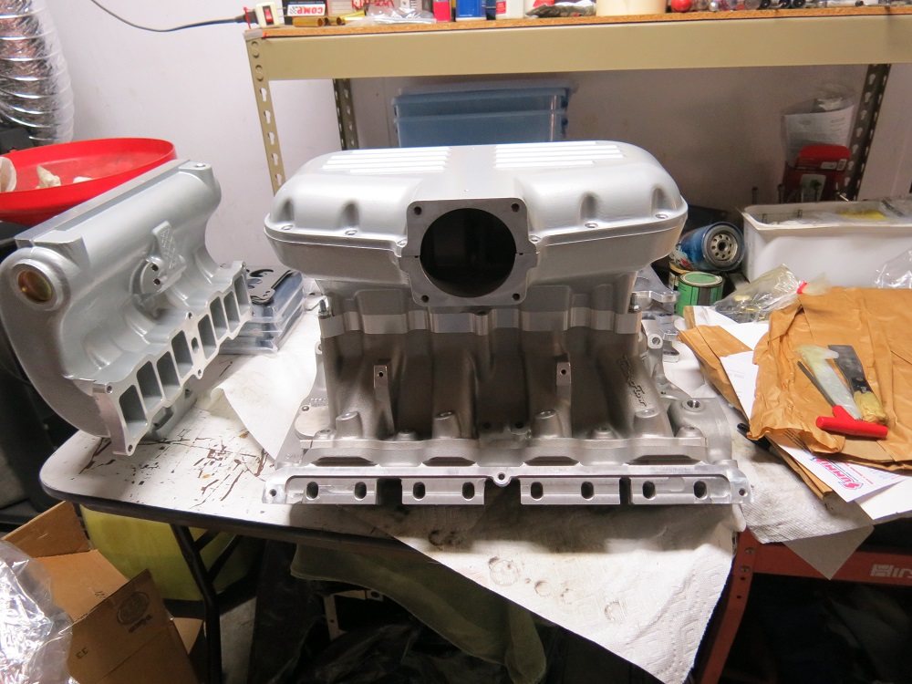
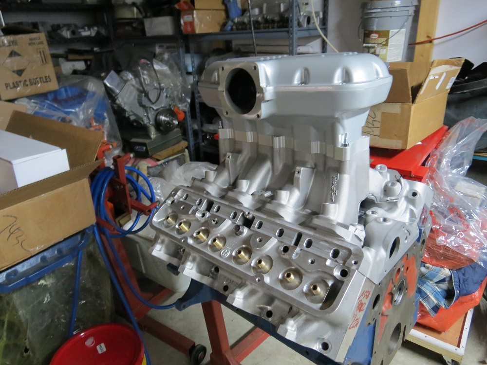
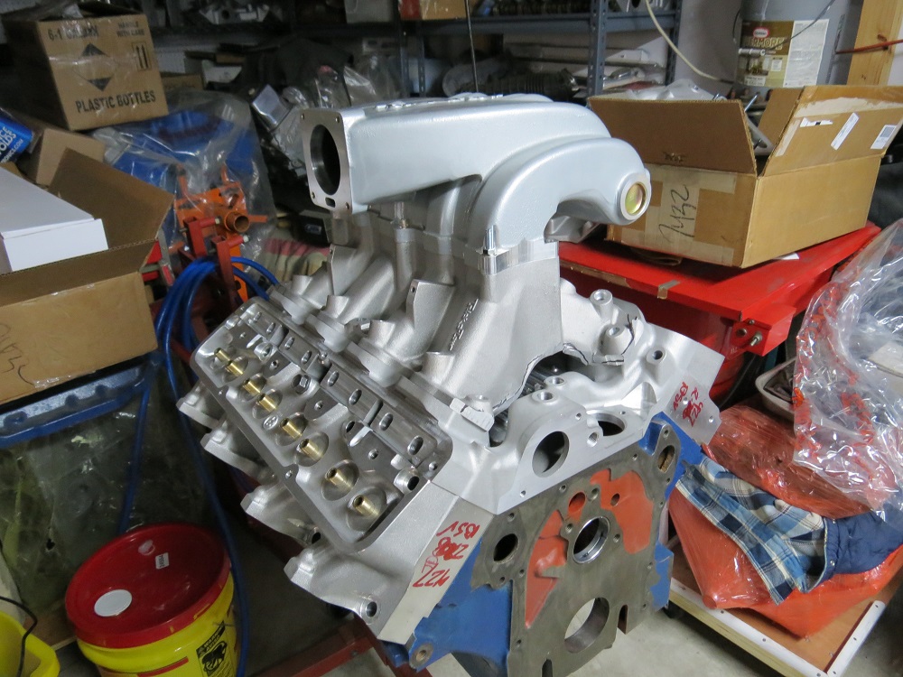
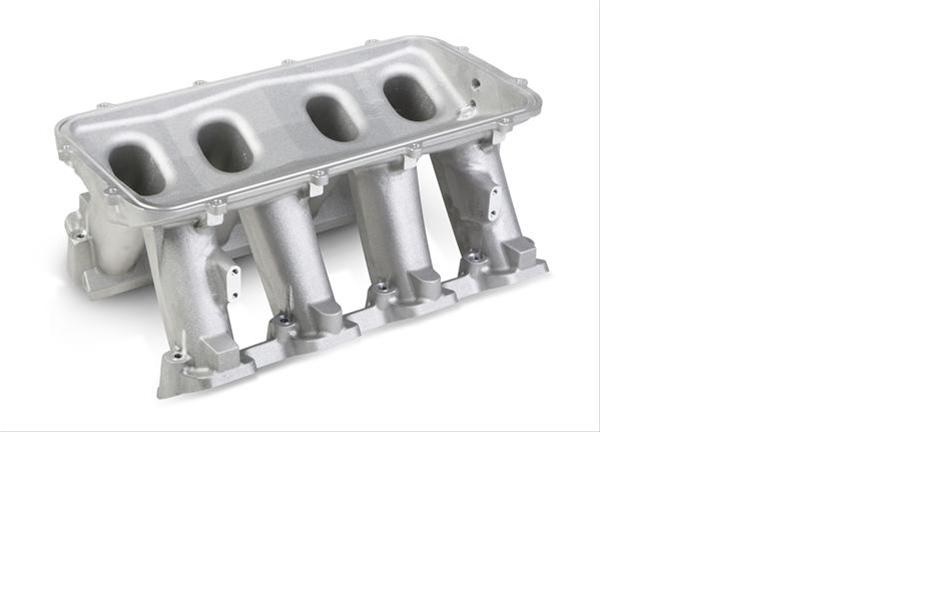
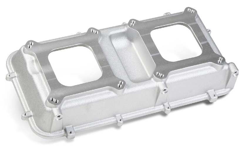
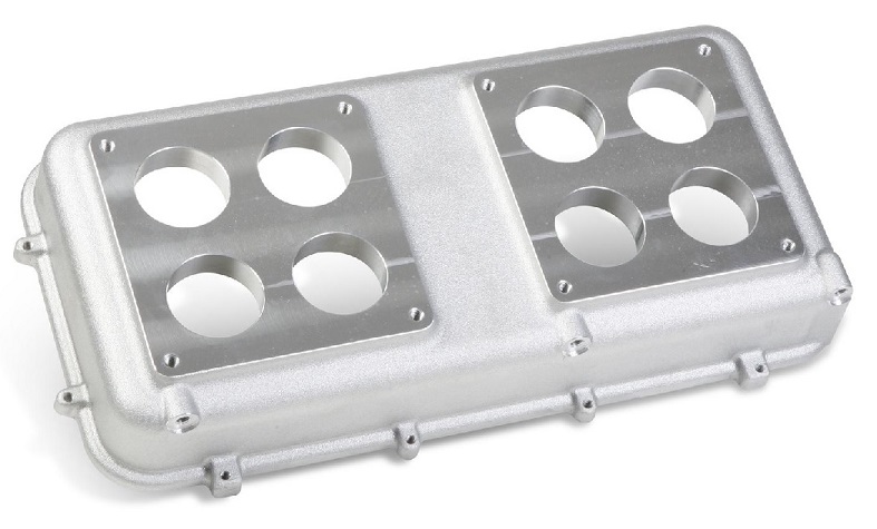
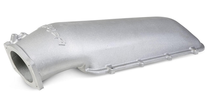
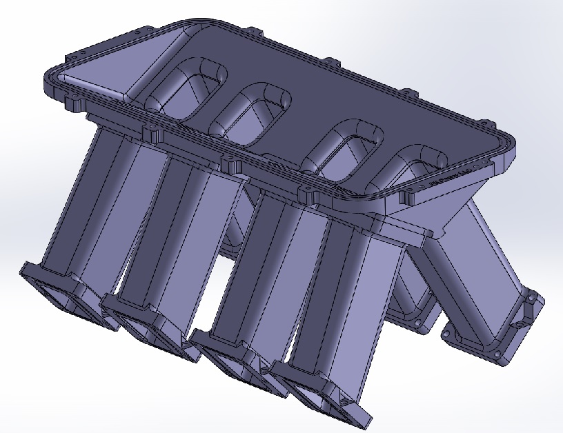
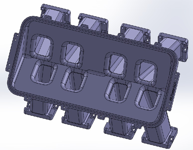
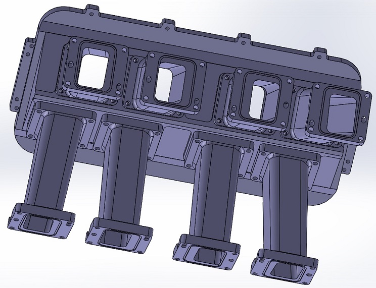
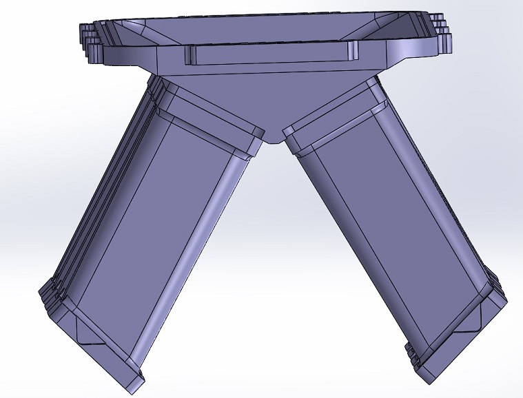
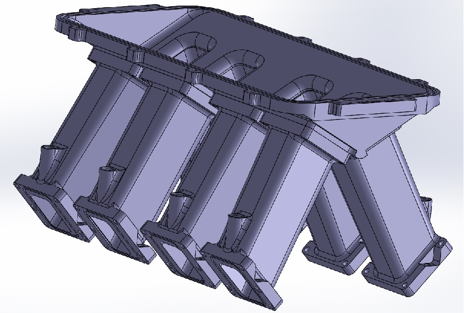
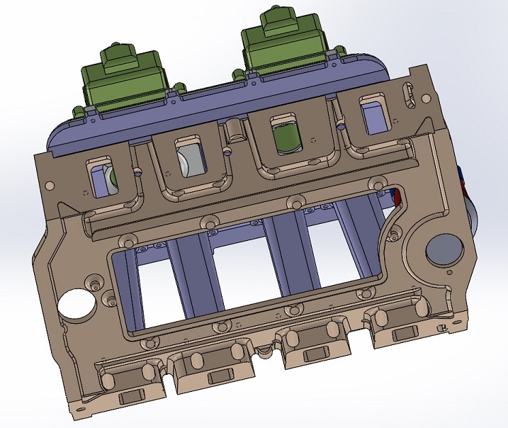
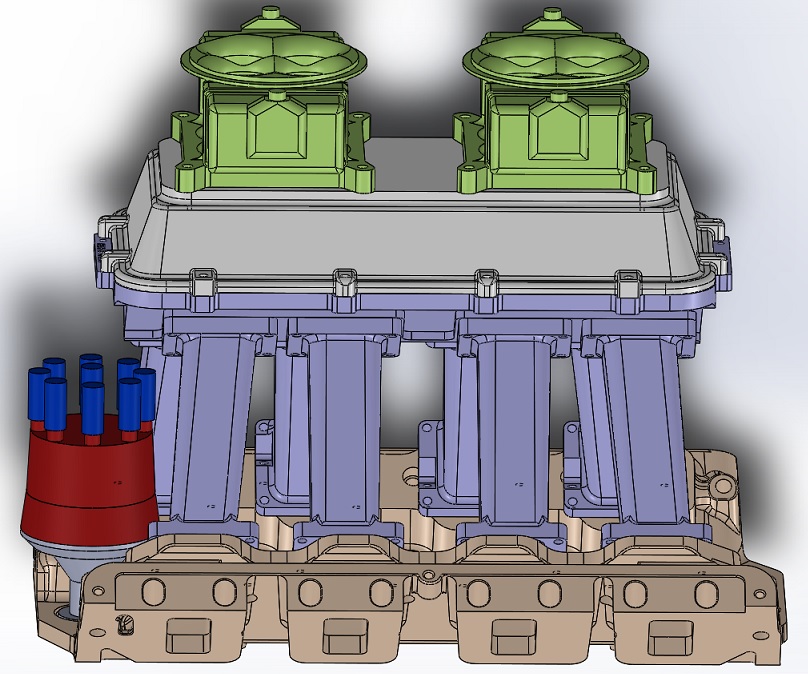
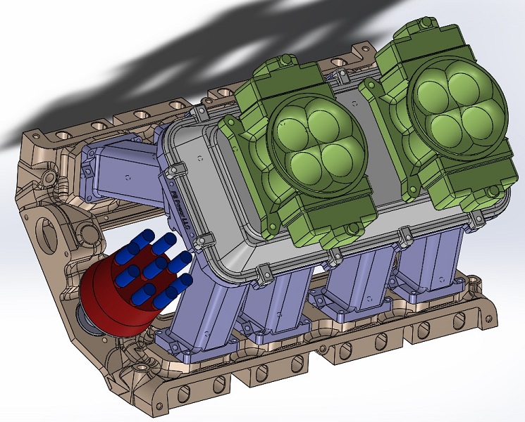
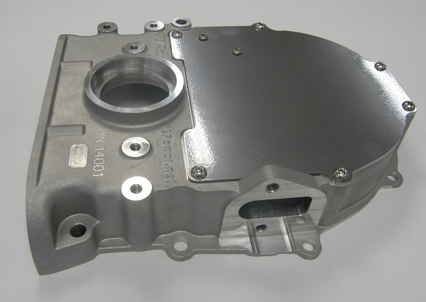
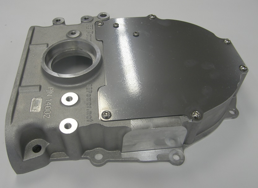
This engine uses one of my intake adapters (#002), and a Weiand tunnel ram for induction.  For carbs, the guys selected 450 cfm Holleys.  I haven't had great luck with those carbs, so I was a little skeptical on this choice, but they got a good deal on them used, and then had them revamped with a Quick Fuel metering plate in the back, that allows jet changes in the secondaries.  So those were the carbs we used.

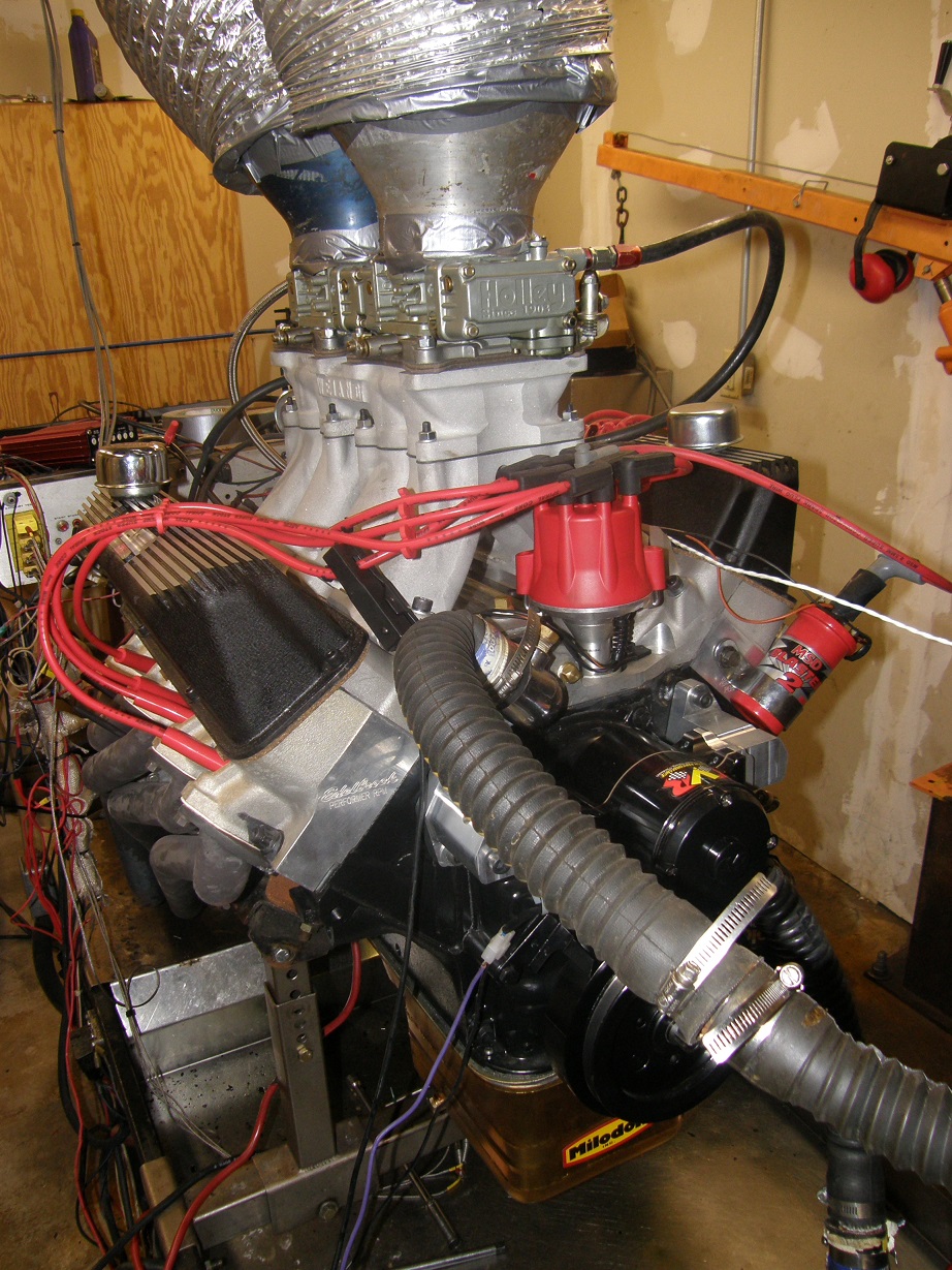
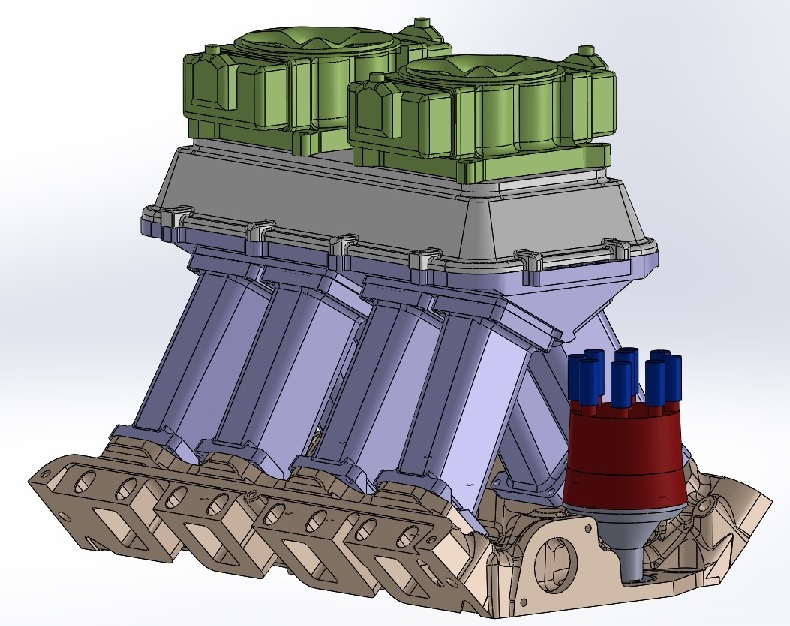
The engine was finished off with a set of my adapters and a CVR electric water pump, a Milodon 7 quart oil pan, and an MSD distributor.  We ran Hooker street headers on the dyno, with the normal 1 3/4" primaries.  We got the engine set up on the dyno in a couple hours on Friday night.  Here's a picture of it at the end of the day on Saturday, after we swapped on a different pair of carbs:


Saturday morning we were ready to go at 9:00 AM.  We filled the engine with water, and, good news, there were no leaks.  The same could not be said for the fuel, unfortunately; the back bowl on the rear carb started shooting fuel out of the vent when the pump was turned on.  I removed the bowl, and the plastic baffle that goes around the needle and seat assembly on these side hung float bowls was just laying in the bowl, not positioned correctly.  It was preventing the float from coming up and compressing the needle against the seat.  Apparently the local carb "expert", who had gone through these carbs, had not assembled this correctly.  Fortunately it was an easy fix, and after re-assembling the rear bowl the leak was gone.

The engine fired right up when we cranked it, and we set the timing as it warmed up, and varied the load somewhat with the dyno in order to help break in the engine and seat the rings.  Since the cam was a roller, there was no need for a cam break-in period, so after running the engine for 10 minutes or so, we shut it off and pulled the valve covers to lash the valves.  They were all a little loose, because they had been set at the specs with the engine cold.  With aluminum heads, as the engine gets hot the heads expand, increasing the distance between the lifters and the rocker arms, and thereby increasing valve lash. 

After getting the lash set to the specs, we started the engine back up and ran a cruise test, just to load the engine in the lower RPM range and see if everything sounded and looked OK.  Looking at the cruise test data everything looked pretty good, but there was a disconnect between the dyno's A/F reading and the reading from my wideband O2 sensor; the O2 sensor looked pretty good, but the dyno reading looked lean.  I wasn't sure which one to believe at this point, so we decided to run the first dyno pull and look again.  We ran the pull from 3000 to 4500 RPM to be conservative.  Here's the first dyno sheet:


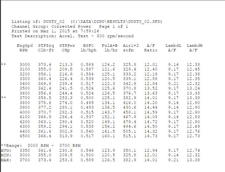
Obviously the horsepower and torque numbers were very disappointing.  On the sheet, the left side O2 sensor (LambdL) was not hooked up.  The right side O2 sensor was reading in the mid to high 12s, which is just what you wanted to see, but the dyno's A/F numbers looked lean.  The engine sounded OK, but not real strong.  We decided to double check the timing, and run another pull; the timing was still set at 33 total, and the second pull looked pretty much the same as the first.

Based on the power numbers I was beginning to suspect fuel as the culprit, but we decided to do one more pull and advance the timing a little as a test.  On the dyno we were running 110 octane race fuel, which allows you to advance the timing quite a bit past the optimum level and not hurt the engine, so we went to about 38 degrees this time.  One thing that we had been noticing about setting the timing was that the distributor was really hard to turn; it was a real fight to get it to move, and then once it did, it didn't move smoothly, so it took us several tries to get the timing where we wanted it.  Back in the pull, we actually lost power with the timing change, so it was time to start looking at the jets in the carbs.

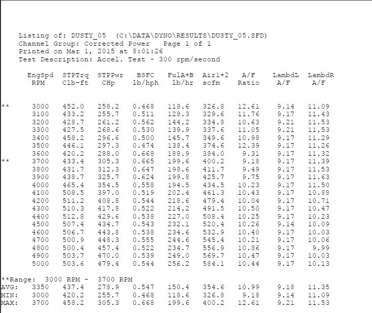
Of course with two carbs its a pain to do the jet changes, but we got started on that and after disassembling the first carb on the primary side, we found it had #59 jets.  This just seemed way too small to me.  I decided to overkill on the jet sizing just to see what the dyno results looked like, so in one carb we replaced the #59 jets with #68s, and in the other we went to #70s (I only had two of the #68 jets in my box).  After re-assembling the engine we started it, and then reset the timing back to the original 33 degrees total, again struggling with the distributor to get the timing set correctly.  We ran the pull, and the engine sounded soggy at the low end but better after 4000 RPM.  The horsepower and torque numbers were a dramatic improvement, as shown in the sheet below:


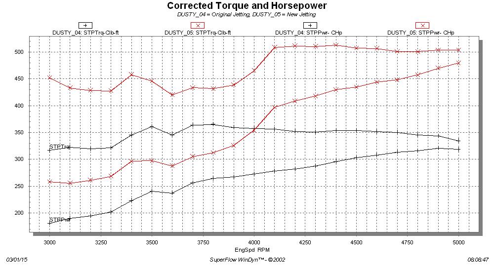
Here's a graph of horsepower and torque, before and after the jet change.  Still looking pretty ragged, but a big improvement:


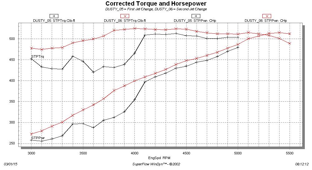
That was a little more like it!  But now, according to the dyno A/F numbers, we were running way too rich.  We decided to do another jet change, and this time we looked at the secondary side as well as the primary side.  The secondaries of the carbs had been fitted with #67 jets.  I decided to ignore the power valves in the carbs and square jet them to make it easier, and work with the selection of jets I had on hand.  So, we put #64 jets in the primaries of both carbs, and #65 jets in the secondaries.  This picked the power up substantially again on the next dyno pull, and we were now pretty close to the optimum 12.5:1 to 13.0:1 A/F range.  Here's a comparison chart of the pull with the new jetting, and the previous pull that was pretty rich:


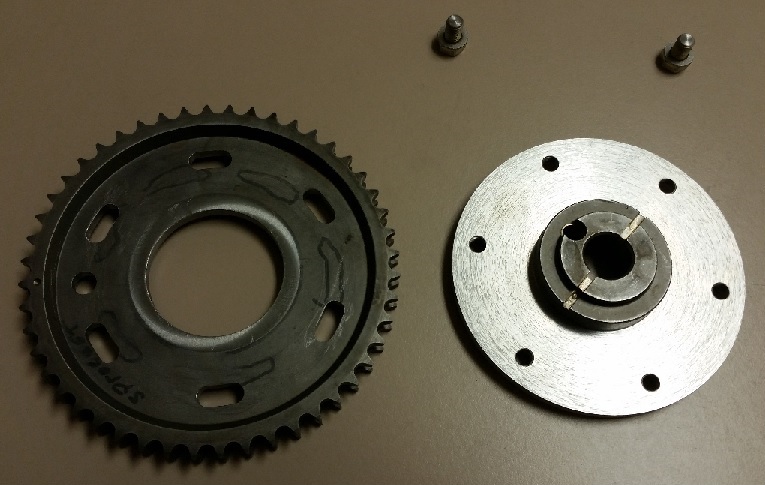
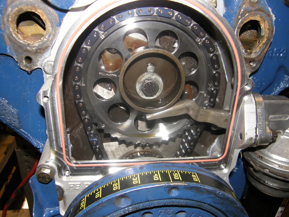
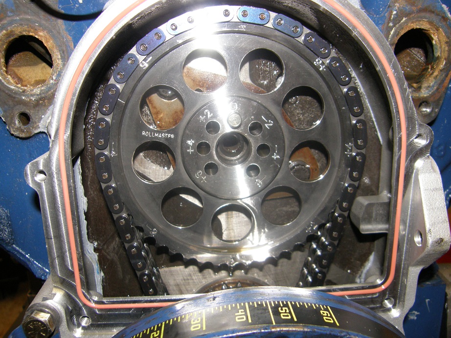
The power levels were finally starting to look like they should.  We decided to do one more test of the timing, and again began struggling with turning the distributor.  I couldn't help but think that it shouldn't be acting like this; it seemed like the body of the distributor was too large for the hole in the block, to allow it to easily turn.  Then I started thinking about the distributor gear itself, and thought to ask whether they had replaced the stock cast iron gear that comes on the MSD distributors with a steel gear, to match the billet steel cam.  The question was met with an "Oops!".  They had forgotten to do that.  Well, now the distributor had to come out, and I was worried that we'd find that the stock cast iron gear had been all torn up, and that there would be a bunch of shavings from that now in the engine.

The distributor was really tight and had to be pried out with a pry bar, but we were all relieved to see that the gear did not appear to be significantly damaged.  You could just barely feel the start of a wear line on the gear.  It wouldn't have lasted long, but fortunately the amount of material that had worn off was really small, so I don't think it caused the engine any problems.  On the barrel of the MSD distributor you could see wear marks, where the body of the distributor was in tight contact with the block, so that was the reason why the distributor turned so hard.  I plucked an MSD distributor with a steel gear out of my vast archive of FE parts ( ;D), and installed that one in the engine.  My distributor turned easily in the block, so the distributor that the guys have will need to be sanded down a little with an emery cloth before it is reinstalled (after a new steel gear is put on the shaft).  That should solve all the problems.  Hindsight being 20/20, its a good thing that distributor was tight; otherwise I would have never asked about the gear on the distributor, and it would have worn itself away eventually, potentially damaging the engine.

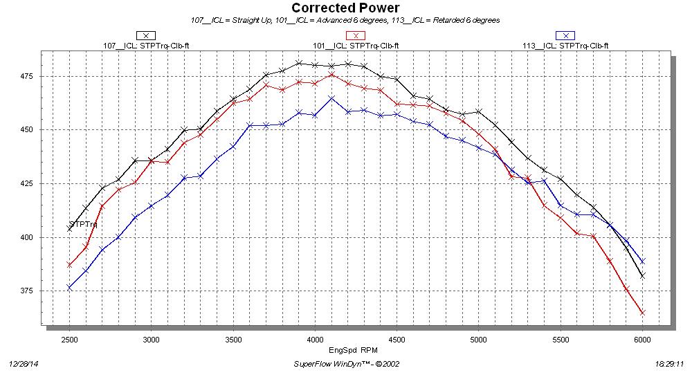
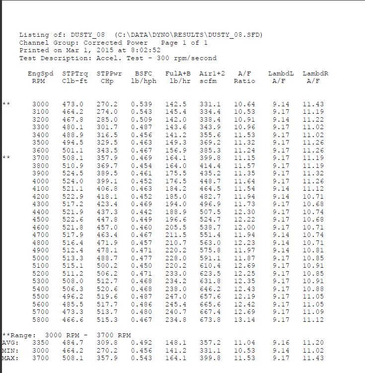
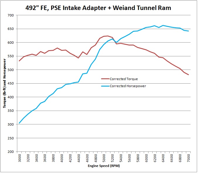
After all that screwing around, we advanced the distributor from 33 to 35 degrees, and got virtually no change in power from the engine on the next pull.  We ran one more, to a little higher engine speed; here is the data and a graph of the final pull, with the 450 Holley carbs:


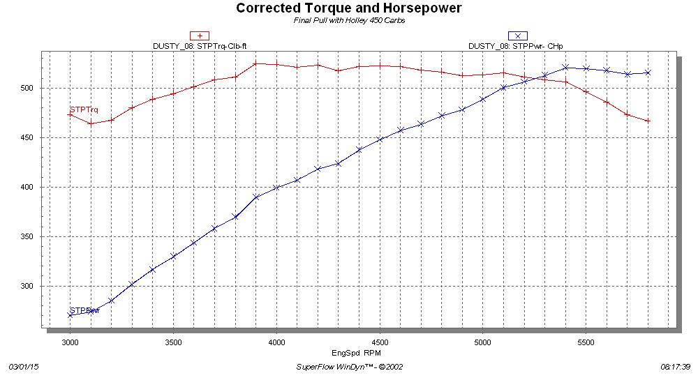
I thought that 520 horsepower and 525 foot pounds of torque wasn't bad, given the heads.  And the torque curve was nice and flat, and close to 500 foot pounds even at 3000 RPM.  This engine is going to be mated up with an automatic and 3500 stall converter, which should be just about perfect for it.  But with that cam I was kind of surprised that the horsepower seemed to be peaking in the 5500 RPM range; I'd figured it would be more like 6000 RPM. 

By now it was just after noon, and I'd been telling the guys all day that I thought the engine would make more power with a pair of 660 center squirter Holleys, and I just happened to have a pair of those.  So, given that we had a little more time to run the engine, we decided to swap on my carbs.  Those carbs are jetted for a lower horsepower engine (my 428CJ, which is around 460 horsepower), but we decided just to bolt them on and run them, and see what happened. 

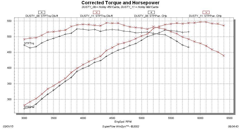
To say that the engine liked the bigger carbs would be an understatment.  According to the dyno A/F reading we are running a little lean with these carbs, pretty much as expected, but the engine still picked way up.  Also, it seemed to want to run higher in the RPM range than before.  We ran a few more pulls, up to 6400 RPM on the last one, and now the engine looked like it was peaking at 6000 RPM, as expected.  Here's the dyno sheet, and a comparison graph between the 450 and 660 carbs.


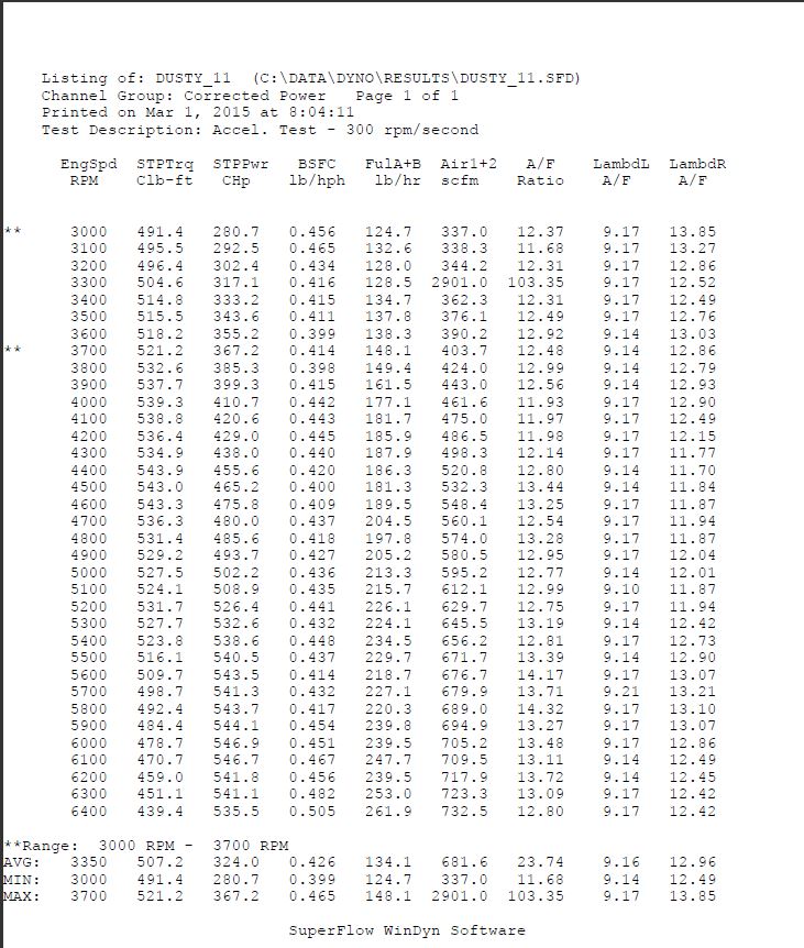
I think that 547 horsepower and 544 foot pounds are really, really impressive numbers given the stock Edelbrock heads.  A street/strip porting job on the heads, getting the intake flow up to 300 cfm, would make this an easy 600 HP engine.  Even as is, its a great hot street engine.  It idled on the dyno between 900 and 1000 RPM with a nice lope, and seemed to have really good throttle response, especially with the 660 carbs.  Can't wait to see it in its new home, a '64 Galaxie...


177
Non-FE Discussion Forum / Super Bowl, who do you like in today's game?
« on: February 01, 2015, 12:46:55 PM »
I would really like to see New England stomp Seattle, but I'm afraid that's not going to happen.  I'm taking Seattle by 7.  What do you think?

178
Non-FE Discussion Forum / Petition to change the NHRA seat belt rule
« on: January 20, 2015, 12:57:16 PM »
Somebody posted this on the FE Forum, and I thought it was worth re-posting here.  Anybody who has taken a perfectly good set of seat belts out of their race car just to conform to the NHRA's 2 year limit on seat belt use can understand the reason for this petition.  The petition is to change the 2 year limit to a 5 year limit.  Go to the link below and add your voice to this issue; I did.  Thanks, Jay

http://www.thepetitionsite.com/147/460/273/make-drag-racing-seat-belts-certification-good-for-5-years-nhra/


179
Vendor Classifieds / FE Timing Covers
« on: January 18, 2015, 01:48:07 PM »
FE Timing Covers

To purchase an FE Power Timing Cover, please go to the link on the main page: 

http://www.fepower.net/Products/fetc.html


- Features:

     - Removable front cover with an O-ring seal, allowing removal of the top timing gear and camshaft through the cover, or changing the cam timing if an adjustable top cam gear is used.

     - Extended bolt bosses for the bottom two bolts, allowing the front corner oil pan bolts to be tapped through more material.  This eliminates the stripped threads commonly found in factory FE timing covers.

     - Additional mounting bosses on the front of the cover around the crankshaft opening, for attaching brackets or mounting additional parts, such as a crank sensor.

     - Provisions to use the stock FE front seal, or alternatively a 351C front seal.  Using the 351C front seal allows the seal to be changed without removing the timing cover, and also allows the use of available 351C double lip seals, for use on engines with vacuum pumps or dry sumps.  (Using the 351C front seal requires the sealing surface of the stock FE crank sleeve to be machined towards the front of the engine).

     - Front cover plate is powder coated in a shiny silver color; black or dark blue powder coated covers are available by special request, at no extra cost.


- Options:  There are two part numbers of the timing covers available; see the description and photos below.

     Part #14001 includes the mechanical fuel pump mount.

     Part #14002 is machined flat with no hole for the mechanical fuel pump. (Note:  FE Power is currently out of stock on the #14002 covers.  They are expected back in stock in early 2017)

Pictures below are of the #14001 timing cover:


Pictures below are of the #14002 timing cover:


Thank-you for your interest in these timing covers!

180
FE Technical Forum / Effect of Cam Timing Changes on Torque and Horsepower
« on: December 28, 2014, 10:28:28 PM »
I've been threatening to run this test for a month, but keep getting sidetracked.  Finally got around to it today.  The dyno mule is my trusty 428 Cobra Jet, now fitted with one of my prototype timing covers, and a Rollmaster timing chain which I've modified to allow cam timing changes at the top gear.  See the FE Timing Cover topic in the Member Projects section for more information on this.

The cam in this engine is a Comp 294S solid grind for the FE.  Lobe separation angle for this cam is 110 degrees, and I installed it 3 degrees advanced, at 107 for the intake centerline.  The conventional wisdom of cam timing is that advancing the cam improves low and midrange performance at the expense of the top end, while retarding the cam improves the top end at the expense of the low end and midrange.  The idea behind this test is to check this out.  Most of the time the "conventional wisdom" can be suspect, so I wanted to see if it held true on this engine, while also taking the opportunity to check out the utility of my timing cover and timing gear setup.

Because of limited time, I decided to just test the cam timing at the straight up position, and also advanced and retarded 6 degrees.  So, In addition to 107, I was going to check the cam timing at 101 and 113 for the intake centerline.

After running the engine for about 20 minutes to warm it up, I ran the first pull as a baseline, and then took a good look at the timing cover to see how it was faring.  I was happy to see that there didn't appear to be any leaks around the removable cover plate, so apparently the O-ring was doing its job.  I had also fitted this timing cover with the 351C front seal, and machined a longer sealing surface on the crank spacer.  This also appeared to be working well, as there was no evidence of any front seal leakage.

Next I turned the engine over by hand to TDC on the #1 firing stroke, and took apart the front of the engine to get at the cam timing adjustments.  Of course this was a lot easier on the dyno than it would be in the car, but even on the dyno I was surprised at how easy it was.  I was using my electric water pump adapters and the CVR pump, and these use O-rings to seal to the engine block, so after draining the water from the dyno's cooling tower I just pulled the four water pump bolts to remove the pump, while the water from the engine drained into a pan below.  No gaskets to mess around with, which was nice.  Next I loosened the one timing cover bolt that holds one end of the timing pointer, and removed the 10-32 screw in the removable timing cover plate holding the other one, and the timing pointer swiveled out of the way.  Then I pulled the six bolts holding the removable plate onto the timing cover, and off it came.  Here's how it looked at this point:


Next I removed the fuel pump and the fuel pump eccentric and cam bolt, to expose the timing holes in the cam gear:


At this point a couple of things became clear.  First, with the oil slinger in place on the crankshaft, you can't see which one of the crank gear teeth is marked, and looking around the harmonic balancer at the crank teeth it can be a little tricky to determine which one is pointing straight up.  You need to be able to see this because when you change the cam timing with this gear you have to rotate the whole cam gear to a new position, and the right tooth has to be pointing down at the crank gear tooth that is pointing straight up.  Next time, I will add a dot of paint on the crank gear tooth so that it is more obvious.

The next thing that became clear was how nice it would be to have one of those Cloyes adjustable top cam gears, like the ones they make for other engines.  Barry R is working on getting Cloyes to do one for the FE, and it would be so much easier to leave the top cam gear in place and just adjust the gear.  But as it is with this setup the top gear has to come off and get rotated to a new position to change the cam timing.

I had learned on the engine stand that the pin that goes in the cam either has to come off with the gear, or come out first; if the gear is pulled forward and the pin stays in the cam, there is not enough slack in the chain to get the gear off.  I put a vise grip on the pin and tried to pull it out, but it was stuck in place, of course  ::)  
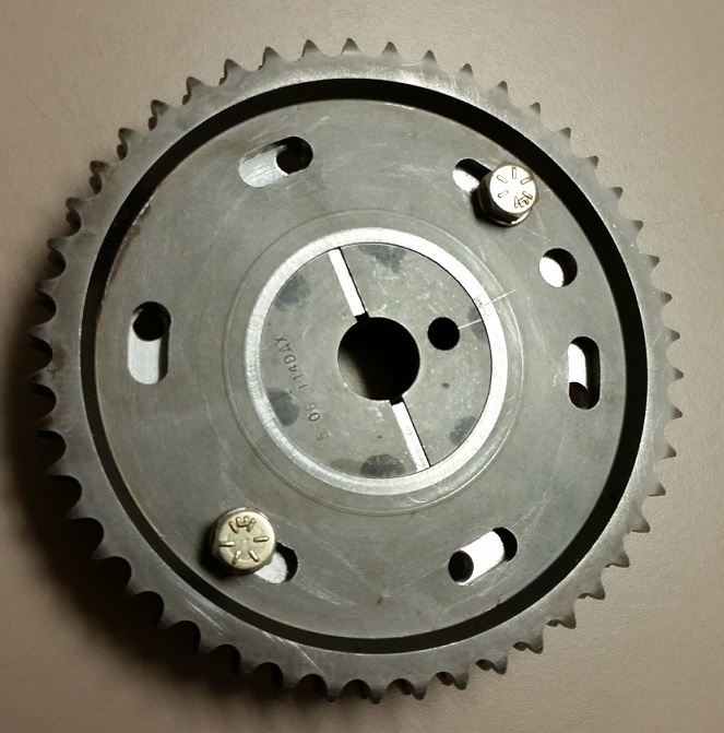
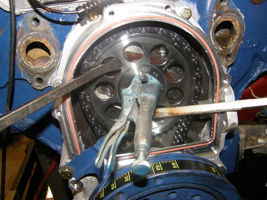
I left the vise grip in place in order to make sure that the pin came out with the gear, and managed to pry the gear loose with a couple of screwdrivers, as shown below:


This really didn't take too long, but it would have been nice to just loosen the six bolts on the Cloyes gear and rotate the crank to get the cam timing that was required.  Maybe they'll have that gear available in a few months...

After the gear came off the stub of the cam the pin can be pulled out, and the gear drops down into the timing cover as shown below:


At this point the chain is not engaged to the crank sprocket, and you can rotate the upper gear to whatever position you want.  I rotated it around to +6 degrees and pushed the cam sprocket back onto the cam, after making sure that the tooth marked +6 was pointed straight down.  Looking through the pin hole in the cam sprocket I could see that the crank was going to have to be rotated somewhat in order for the pin to line up, so still gripping the pin with the vise grips I pushed it into the hole and then rotated the crank with a wrench while pushing on the pin.  After what I assume was six degrees, the pin slipped into place in the cam. 

I torqued the cam bolt to 60 foot pounds to make sure the gear stayed in place.  Re-assembly was pretty quick; the whole process from start to finish took about 45 minutes.  I warmed the engine back up and ran two back to back dyno pulls to make sure the results were consistent.  Then, I repeated the process, retarding the cam by 6 degrees.  But when I ran the dyno pulls this time, I got nearly identical results as with the cam advanced 6 degrees.  I couldn't believe that this was accurate, so I figured I must have screwed up somehow.  I pulled the right valve cover and put the dial indicator on the #1 intake valve to check the cam timing.  It came in at an intake centerline of 98 degrees!

After a couple minutes I figured this out.  There are 24 teeth on the crank gear.  Therefore each tooth is worth 15 degrees.  I had put the cam gear back one tooth off on the crank gear.  This advanced the cam 15 degrees, but the cam pin hole I'd used was 6 degrees retarded.  Advanced 15 less 6 degrees retard means an advance of 9 degrees; 107 was straight up, and 9 degrees advanced was 98 degrees. 

I repeated the whole process again to get the cam timing right for the next test.  This time, when I grabbed the pin in the cam gear it cam right out, and I was able to pull the cam gear off the nose of the cam easily.  After re-setting the cam gear, I double checked the cam timing to make sure I had 113 for the ICL, then re-assembled the engine.

After warm up and two more back to back pulls, this time with more believable results, I ran through the whole process one more time to put the cam timing back where it had been initially.  Again this time the pin pulled out easily and the cam gear came off with me just pulling on it.  This time I changed the cam timing in 25 minutes.  I got the same results with the cam timing in the original position as I had at the beginning of the afternoon, so right now I feel pretty confident in the results.

And the results are as follows:  Advancing the cam cost a small amount of power all across the RPM range, but especially at the top end.  Retarding the cam cost a LOT of power at the low end and midrange, but at 5800 RPM the 113 ICL started making more power.  This part, at least, is more or less in line with expectations.

Dyno charts are below, with torque and horsepower on the same chart, and then also shown on separate charts.  This engine has standard 390 rods with ARP bolts, so I don't want to run it past 6000 RPM, but I'm sure that the retarded cam would have looked better over 6000 RPM based on these results.  I don't understand why the advanced cam didn't make more power down low, and maybe if I had advanced it less than 6 degrees it would have.  But just based on the data I have, this engine doesn't quite behave in the conventional fashion.


Bottom line for me is that the timing cover can be used to change cam timing, and it seems to work on the engine just fine.  Its not even that tough LOL!  But you'll need dyno or track data to determine if you've moved in the right direction with the cam timing, because at least with this engine, it didn't quite follow the conventional wisdom...

Pages: 1 ... 10 11 [12] 13 14 ... 25