Show Posts

This section allows you to view all posts made by this member. Note that you can only see posts made in areas you currently have access to.


Topics - jayb

Pages: 1 ... 7 8 [9] 10 11 ... 25
121
This is going to be a "living" post, because I don't have time to write it all now.  Sorry I haven't been giving my usual updates, but I arrived at Drag Week this year sick, and it has taken me a few days to recover.  Right now I am running second in class behind Brad Dyer's Nova, which has a new motor and pretty much has me covered at this point.  My car is not 60 footing like it should, down about half a tenth from last year.  Pretty sure that the switch to 4.11 gears, from 4.29s, was a mistake.  The engine is running strong but is leaking some oil from up in the dry sump tank and oil filter area; going to try to get that resolved today.  I will try to do a play by play a little later and add it to this post; lowlights include the drive from National Trail to Norwalk, which was brutal and confusing, and we didn't get in until 1:30 AM Tuesday, and registration, where we were in line waiting to get checked in for over 8 hours.  Highlights were getting back in touch with old friends and watching the cars go down the track.

Updated 9/14/16:

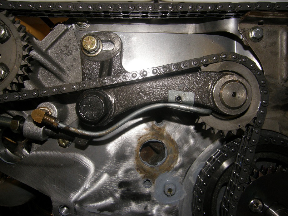
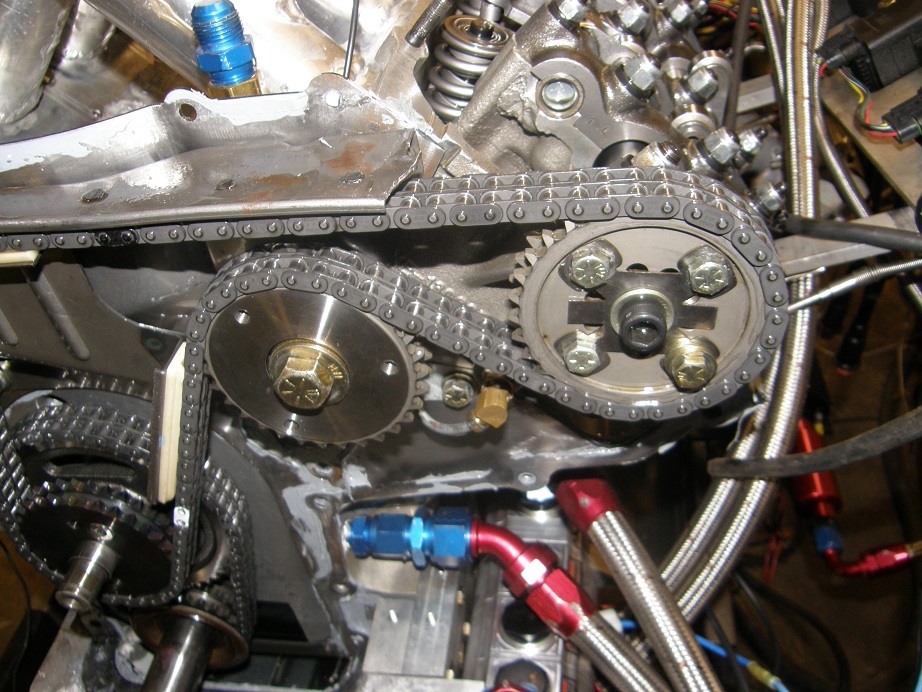
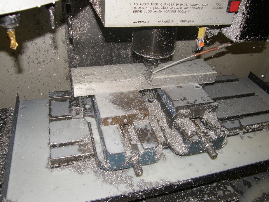
Friday I had the day off to get packed and ready for the trip to Columbus.  My plan was to fix a minor electrical issue,  take the car off for a car wash, then get back home, pull the valve covers, lash the valves, check the timing chain tension, pull the mufflers and bolt on the slicks, and then start packing.  I figured I could get this all done by noon.  Steve was coming over to help me out about 1:00 he said; I got going at 7:30 figuring I had plenty of time.  Solving the electrical problem was easy, and the car drove fine back and forth to the car wash.  Around 9:30 I pulled it back into the garage and started on the valves.  Pulled the valve covers and started to rotate the engine around to #1 when I noticed - Crap! - one of my rocker arm rollers didn't look right.  Sure enough, it was rough on the edge, with a matching rough spot on the cam.  It was the #6 intake rocker.

Well, this of course added some time to my plan.  I was immediately concerned that I could be seeing the start of multiple rocker arm failures.  These rockers were not new, having already gone through one Drag Week plus another 800 or so street miles.  I had lost the #5 exhaust rocker at Drag Week 2015 and I had been hoping that one was a fluke, but of course a second failure put that theory to rest.  There was nothing to do but change the rocker, so I set to work doing that.  I had planned to bring a complete spare set with me to Drag Week anyway.

Steve arrived early, while I was still finishing up, but by 1:00 the engine was buttoned back up and I was ready to start packing.  I have a three page list of items to bring with, all of which have to be found (not necessarily easy!), packed in the right box, and set outside of the shop to be loaded into the trailer.  It took Steve and I until almost 6:00 to get everything collected and organized.  Next we decided to put the car on the trailer, and then back the truck and trailer up to the shop for loading.  Steve and I had already loaded the small Drag Week trailer into the back of the pickup.  I started the car and pulled it around, and drove it up on the trailer.  We got it strapped down, and only then did we notice the stream of transmission fluid that the car had been leaking all the way up the trailer.  We certainly couldn't leave it like that, so back off the trailer it came, and into the shop.  We jacked it up in the air to look for the leak.  The first thing I did was to open the drain on the overflow can at the bottom of the transmission.  Enough fluid came out that it looked like it had been full; maybe it had overfilled the overflow can and was come out of that?  We started the engine  up and left the drain open while the car was running, and a steady drizzle came out of the overflow for a couple minutes, then gradually stopped.  I'd never touched the fluid level after changing from the Gear Vendors overdrive to a standard tailshaft, so our guess was that for whatever reason, the transmission needed less fluid without the overdrive attached.  We closed up the overflow and figured that we'd watch the problem.  However, while the car had been up in the air running, I had found another problem.  My water pump was leaking, between the electric motor and the pump body.  Not much, just a drop every 3-4 seconds, but enough to be a concern.  By this time it was nearly 8:00, and I wasn't going to change water pumps at that point, plus we already had the spare pump in the spares box.  So, we took the car off the jacks and loaded it onto the trailer again.  We had been hoping to leave by 6:00, but by the time we got everything loaded and were ready to leave it was 9:30.

We had been getting updates on Joel's GTX all day, and by the time we left Joel and Jeff had still not gotten the engine fired.  Steve and I drove for two hours and then called it a night, staying at a Wisconsin hotel.  By the time we got to the hotel, I had a fairly bad sore throat.  I hardly slept a wink all night.

Saturday we were up early, and I was still feeling lousy, but popping Advils and sitting in the air conditioned truck for the trip to Columbus wasn't so bad.  We arrived around 7:00 PM to a packed hotel parking lot, as usual, and ended up parking the truck and trailer on the grass.  We spent a little time talking to some old friends, who stood well clear of me as soon as they heard me speak LOL!  I could hardly talk with the sore throat.  I went to bed early on Saturday night, hoping to feel better in the morning.

Sunday morning my sore throat was gone but this summer cold I had picked up had moved into my head, so I still felt pretty lousy.  I had decided during the trip down that I didn't want to go through Drag Week tech with the water pump leaking, so at 8:00 AM Sunday I was out in front of the car on the trailer, working on getting the water pump changed.  That took an hour or so, and after Steve and I had breakfast we headed to the track for the long wait in the registration line.  We arrived at about 10:00, unloaded the car, and went to the back of the line.  Every half hour or so, the cars moved up five or six places; the pace was positively glacial.  We spent the time between moving the car chatting with new and old friends, and I was happy to see Doug Smith again after 11-12 years, and meet his son and wife at the track.  Joel and Jeff arrived just after we did, having driven all night in Joel's convertible GTX.  They had thrown in the towel on the race GTX at 3:00 AM Saturday morning, when the engine fired but did not deliver the expected oil pressure, so they pulled Joel's stock Hemi GTX convertible out of the garage, and headed off Saturday morning in that. 

Eventually while we were in the registration line Keith Turk, the race director, came by and said that the NHRA tech inspectors at National Trail were being very meticulous and checking everything; this was slowing down the registration process, and Keith said there was nothing he could do.  We ended up sitting in the registration line for 8-1/2 hours, until we finally got through around 7:00.  It was hot and uncomfortable, and one of those parts of Drag Week that isn't any fun at all, but we finally made it through.  Sitting out getting sunburned for 8 hours didn't make me feel any better either, but at the end of the night Steve, Kevin, Joel, Jeff and I snuck into a Red Lobster right before they closed and had a nice dinner.  We went to bed that night around midnight, and again I was hoping to feel better in the morning.

Monday, Drag Week Day 1 (updated 9/16):

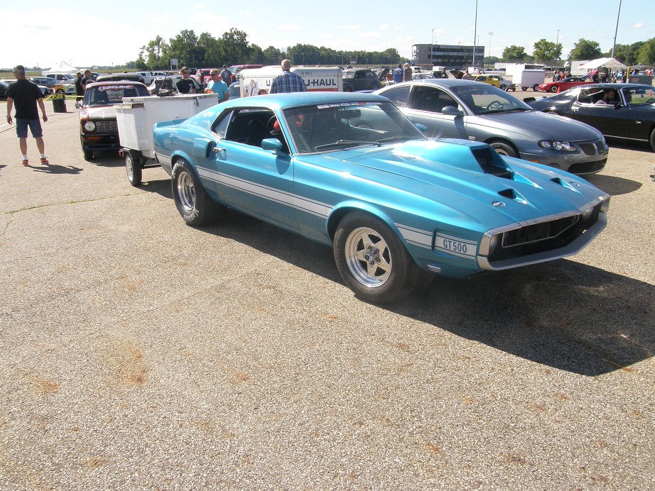
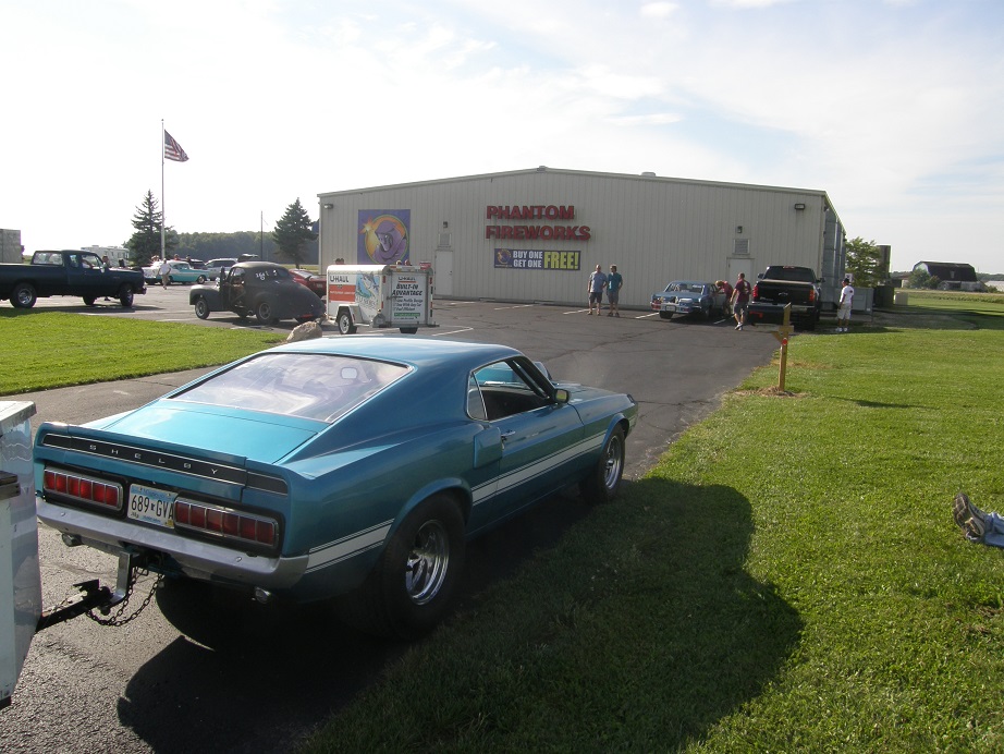
Again, sorry for the late updates but this has been a very busy week.  Before going onto Monday, here is a picture of the car in the registration line at National Trail, from last Sunday:


Monday morning we got into the track and got unloaded.  The drivers meeting started at 8:30 and had the usual information, including 346 cars at this year's event!  Of course, they had 400 registered, and a bunch of cars that were not registered showed up and got in since the event wasn't full.  I'm thinking Hot Rod collected over $130K from the racers to orchestrate this event.  Sure has grown into a big thing.

After the driver's meeting Steve and I finished getting the car ready to race and got into the staging lanes.  We waited there for at least an hour and a half; there were multiple problems on the track, including oildowns and at least one crash, but finally I got to the line in the left lane.  I was really looking forward to the results of this pass; the car was 100 pounds lighter than it was before, and picked up a little horsepower over last year, and with the change to 4.11 gears I figured it would pick up a tenth.  On the launch and going down the track, it felt pretty much the same as last year, and sure enough, the time slip showed an 8.94 at 150.7 MPH.  The ET was nearly identical to what I had been running last year, but the MPH was up by a couple.  However, the really disappointing thing was the 60 foot time.  Last year I'd been running very consistently in the 1.29 area, with a fast time of 1.28.  On this pass, the 60 foot was 1.336, significantly slower than last year.

Jeff had taken a video of the car from the side on the launch, and as we watched it in slow motion the car hooked for about 10 feet, and then as soon as the front suspension topped out, it started to spin.  We decided to try some chassis adjustments to address this issue, so I stiffened up the front shock setting a few clicks to keep the front end from topping out as hard, and also tried another pound of air in the tires, because they looked like they were being crushed pretty good by the launch.

We had to wait until the open session to get back out on the track.  One thing I've noticed this year at Drag Week is with all the cars running, and most of the classes faster than before, there are more stoppages to the action, so waiting in the staging lanes is longer.  As a result, there is not the time to make multiple passes like there has been in the past.  By the time I got back up to the starting line again, it was 3:00 PM.  Again Jeff recorded the car from the side on the launch, and the changes seemed to have made no effect on the traction; the car was doing the same thing.  This time I ran an 8.966 @ 150.63 MPH, with a 1.34 60 foot.  In the past I've always run slow at National Trail, and I chalked the traction problems up to that.  Hoping to run better at Norwalk, we got the car back into street trim, packed up, and headed out of the gate for the drive at 4:30.

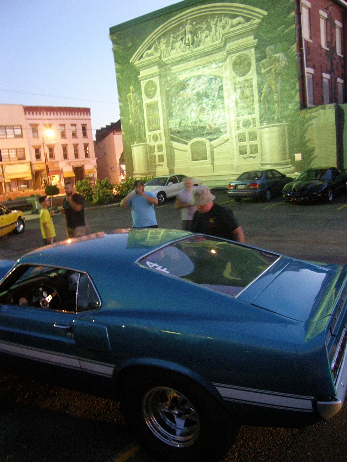
At the driver's meeting they had warned us about this route.  Using normal roads, Norwalk is only about 80 miles from National Trail, but our route instructions took us way out of the way, to cover about 250 miles.  I would say that before we were done on Monday, we covered more like 300.  The instructions were terrible.  We took several wrong turns trying to follow the directions.  One direction even led us down to a road that was closed!  Another example was the instruction to go two tenths of a mile and turn right on some road, when in fact you actually had to go over ten miles before you found the right road.  My co-pilot Steve does not have a smart phone, and it was difficult for me to use mine while I was trying to drive the car, plus it wasn't long before we were trying to find our way in the dark.  Short story, it was a big mess, and everybody was complaining about the directions the next day.  Nevertheless, we finally made it through the route and into our hotel at around 1:30 AM Tuesday morning.  Here are a couple of photos showing the checkpoints on the route:


Tuesday morning we left the hotel around 7:30 for the track.  I had been concerned that the car wouldn't start on Tuesday morning, because at the end of the drive last night the voltage gauge had been dropping a little low, below 13V, and also because when I came outside on Tuesday morning one of the Aussies pitted at the same hotel had mentioned to me that he had shut my door that morning.  Apparently in my tired stupor at 1:30 AM I had not completed closed it, and the dome light had been on all night.  Despite these fears, the car fired right up; the starter issues I had last year have not been repeated this year.  We found our way to the track and got the car ready to race; my 8.94 was second best to Brad Dyer's 8.90 on Monday, so I was currently running a close second in class.  I was pretty sure that I would run better at Norwalk than I had a National Trail, and was hoping that my 60 foot time would come back into line to get me into the 8.70s, which had been a goal for the year.

Once again we had to wait quite a while in the staging lanes, and while we were up there Larry Kortkamp came by.  It was great to see Larry again (who runs the 64 wagon Battlestar Galactic in his race series), and we spent some time catching up.  Larry commented that last time we met up at Drag Week in 2009, he had been able to drive his 64 blown Galaxie right into the pits and park next to us, but that the event has gotten so big that all the spectators were confined to a separate area for parking now.  Looking around in the staging lines, six lanes filled with the class cars, it sure drove the point home.

Finally I made it to the line, and made the pass.  The car didn't feel like it left any harder, but it ran its normal straight as an arrow pass.  The time slip was very, very disappointing to me, at 9.01 and 150.6.  Sixty foot time again was at 1.34.  It was clear that the car had slowed down significantly from last year in the 60 foot department, despite the weight loss.  It was equally clear to me at that point that the switch from 4.29 to 4.11 gears was the culprit.  I was only running 7400 or so through the traps this year, which was what I had wanted to accomplish with the gear change, but I had left a bunch of time on the starting line as a result. 

Brad Dyer's Nova came up and made a great pass, an 8.64, and at that point it was clear that there was no way I was going to be able to hang with him this year.  As a result, I elected not to make a second pass, and set about packing up for the road trip.  Given the brutal drive the previous night, I wanted to get out of the track as soon as possible anyway, and try to get the drive finished during the daylight.

Before we left one of the Hot Rod guys came up and did a nice interview with me about the car and the engine, not sure where that ended up, if anywhere.  Finally we got on the road just after noon.  This time, Jeff drove with me, and Steve drove with Joel.  We had cleared the trunk monkey swap with Keith Turk, the race director, on registration day, so we could have a little variety for the drives.

The route on Tuesday was 100 times easier than the one on Monday.  We were on our way up to Martin but our hotel was in Kalamazoo, a good 25 miles from the track.  The worst part of the drive was the waiting to get onto one of the interstate exits we were supposed to take.  We waited, idling, for at least 20-25 minutes, in the hot afternoon sun.  Water temp on the car creeped up to 210, and without any anti-freeze and only a 6-8 pound cap, I was worried about boiling over.  But finally we made it onto the freeway and got going down the road.  Hindsight being 20/20, I think this extended period of idling caused me some problems on Wednesday.

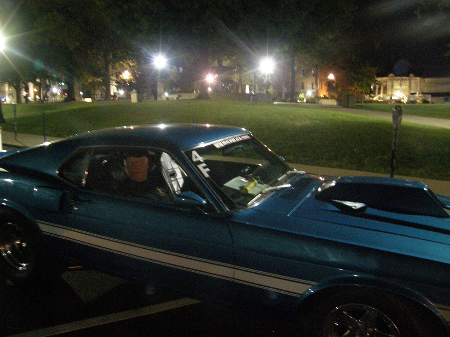
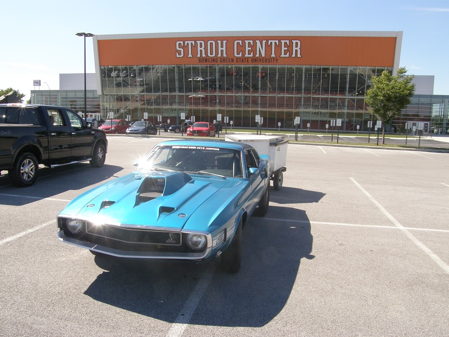
We made it into the hotel around 9:00 PM on Tuesday night.  Here's some pictures at the checkpoints along the way:


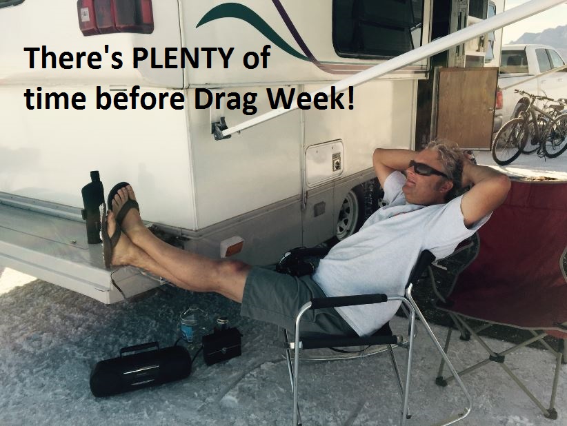
We had decided to get together for dinner, but when Joel pulled in with the GTX, he didn't have his driver's side power window working.  He decided he had to take the door panel off and fiddle around to get it working.  All the rest of us were starving, and just couldn't wait around any longer to help Joel, so Jeff, Steve and I headed across the parking lot to a local restaurant, and Kevin followed shortly thereafter.  I was looking forward to having Joel join us, because I had a present for him.  Joel had interrupted his preparations for Drag Week in August in order to go to Bonneville, and in the end it cost him, because he ran out of time to get his red GTX ready.  I had this photoshopped picture of him relaxing at Bonneville framed and ready to give to him on Tuesday night:


By 11:30 Joel hadn't yet shown up, and I was still feeling pretty lousy from my cold, but while sitting on the stool at the table suddenly I got a bad cramp in my leg.  I stood up to straighten it out, and started to feel lightheaded, so I sat down again.  A moment later I passed out, head down on the table.

There is still some disagreement about what was being said while I was unconscious, but from what I can gather, if I was dead there was going to be an argument about who got to keep the race car LOL!  Fortunately the guys shook me awake pretty quick so I got to keep the car myself ;D  I figured for me to pass out, I must still be sicker than I thought.  I still felt pretty shaky when Joel arrived a few minutes later.  I gave him is framed picture, and then got back to the hotel and crashed.  I'll put Wednesday's report in a separate post - Jay

122
The Road to Drag Week 2016 / Drag Week 2016, Quick Update September 10
« on: September 10, 2016, 10:14:01 PM »
Things have not gone according to plan for me and Steve, or Joel and Jeff, or Kevin.  At least Steve and I are at the hotel now, but we have some work on the car to do in the morning before heading to the track.  Joel/Jeff and Kevin are still not here, probably arriving in the morning.  Nothing is easy, because its Drag Week  ::)  I'll try to post a detailed update tomorrow night - Jay

123
The Road to Drag Week 2016 / The Road to Drag Week 2016 - September 5
« on: September 05, 2016, 09:37:06 PM »
Just a quick update tonight, really no time to write all the stuff that has happened down.  But in any case the car is together, the engine runs, I've broken in the rear end gears on the jackstands, and I'm pretty close to a test drive.  Which is good, because I need to drive it to my friend BradFORD's shop for an alignment later this week.  Minor problems I'm still addressing include a small water leak, the electric fans coming on when they are not supposed to, a couple of oil drips from the dry sump fittings, etc.  Should be able to finish up all the last items tomorrow, test drive Wednesday, front end alignment Thursday, and on the trailer for Drag Week on Friday.  Talk about cutting it close...

Special thanks to my friend Jeff (JericoGTX) for his help on the fiberglass bumpers this weekend.  Jeff took over that project when I just didn't have the time to get it done, did all the bodywork, tried a chrome wrap (that didn't work), and then finish sanded and painted the bumpers.  We were going to try the spray on chrome stuff, but there wasn't time, so that will have to wait for sometime after Drag Week.

124
Sorry I haven't been keeping up on this blog.  I like to provide an update once a week, for myself if nobody else,
because it is always interesting to go back and re-read this stuff to familiarize myself with whatever problems
this year's Drag Week thrash uncovered.  A good learning experience, if nothing else.  Anyway, after a pretty
brutal three weeks since the last update, I am now about one week behind where I wanted to be, and it is clear
that I am not going to be able to make a trip to the track next weekend.  But unless some serious problems
come up over the next two weeks, I think I will be making it to the event with the Shelby clone again
this year.

As of August 8 I had the sheet metal intake pretty much done, and the cylinder heads were finally in my
possession, so I was planning to start the engine assembly.  But before I did that I really wanted to finish
the wiring in the car for the new EFI system.  I figured that this might take me a couple evenings, because
a lot of it was already done.  Of course, I should know better than this by now.  By the time I got done,
I had burned every evening that week, and didn't get finished until Saturday about noon.  But, the good news
was that I was able to completely remove the EFI system wiring from the car, in one big harness, so that
it could be easily transported over to the dyno for hookup on the engine.  Here's a picture of the wiring
harness on the floor, after I removed it from the car.


Doesn't look like much, but it took a long time to put together.  The area around the car looked like a disaster LOL!


On Saturday afternoon the 13th I finally got going on assembling the cylinder heads.  First thing was to check
clearance around each valve at the pistons.  My last set of "no-name" cylinder heads had one chamber that for
some reason was shifted off center from the standard bore spacing, and had caused some piston to valve issues
on cylinder #4.  I assembled both heads with the valves and checker springs on all valves, installed them on
the engine with clay on all the pistons, then brought each piston to TDC and compressed the valves into the
clay.  Thankfully, the valves were all centered properly in the valve reliefs.

I was using new springs and spring seats, so I had to check the installed height on every valve and then assemble
them with the new valves in the heads.  This took me most of the rest of the day Saturday, but by Saturday night
I had both heads assembled.

Sunday I had limited time, because at 6:00 PM we were planning to go off on a brief family vacation.  But I did
manage to get both heads installed, and also the timing cover backing plate installed, before we left.  I had
taken the whole next week off, but was only going to be gone through Wednesday, so I had a four day weekend
coming up after the vacation.  I figured I could get the rest of the engine together on Thursday and Friday,
be on the dyno on Saturday and finish all the tuning on Sunday, then pull the engine off the dyno and get it
in the car on Sunday night.

Naturally, this didn't quite happen as planned.  It took me all day Thursday, all day Friday, and most of the day
Saturday to get the engine completely put together.  I had to spend some time machining a new part for the dry
sump drive, then I tried to rebuild my ATI harmonic balancer, but failed (couldn't get the shells apart to
replace the O-rings), had some trouble getting the cams degreed correctly, etc. etc. etc.  As usual, seemed like
one thing after another.  My friends Steve and Kurt were over to help on Saturday, but couldn't do too much until
I had the engine finished.  Finally on Saturday evening, with their help, I got the engine mounted on the dyno.  I
worked late on saturday night starting the hookup.

Sunday morning I got going early but again it took me most of the day to finish the hookup on the dyno.  I had to
install a different fuel pump than the one on the dyno for use with the EFI system, get the coils taken out of
the car and installed on the dyno so they could be hooked up, set up the whole dry sump system, etc. etc.  Its
always a lot of screwing around getting this engine running on the dyno, and after three solid 14 hour days on
it I was moving kind of slow by Sunday.  My friends JC and Royce came over that afternoon to give me a hand,
and JC was so horrified by the condition of the area around the car that he cleaned it up for me LOL!  Anyway,
by 6:00 PM or so on Sunday, we were finally ready to run.  But all I had time for was a warm-up run; after the
warm-up I wanted to do a bunch of checks, like lashing the valves and checking the chain tension, and by the time
I was done with that, it would be too late to run any dyno pulls.  In any case, though, after some struggles with
the starter, I was glad to see that the engine started right up and seemed to run fine.  It sounded good, oil
pressure was good, it was cooling normally, etc.  After the 20 minute warm-up run, JC and Royce took off, and I
started taking the valve covers off for checking the lash and the chain tension.  This is when the real trouble
started.

On the right side of the engine there is a chain tensioner arm for the SOHC secondary timing chain (the long one).   
Here is a picture of this tensioner:


There is a large, 9/16" bolt that goes into the cylinder head, that this chain tensioner pivots on.  There is
a smaller, 7/16" bolt that is accessible from the right valve cover, that contacts a part of the tensioner;
you screw in this bolt to tighten the chain.  Then, there is another 7/16" bolt, above the large bolt, that screws
into the head and locks the chain tensioner in place, once the chain is correctly tensioned.  When I had
put the engine together on the stand, I had torqued the large bolt to 60 foot-pounds, and the smaller locking
bolt to 35 foot-pounds, which are the normal torque measurements I use for these two bolts.  The adjuster
bolt that is accessible through the valve cover isn't torqued, because it is only used to tension the chain.  After
re-tensioning the chain on the dyno, I went to torque the large bolt to 60 foot pounds.  And - it stripped.

Crap!  Now I had to figure out how to heli-coil that hole, with the engine all together.  I always worry about
the chain tensioner bolts, because they seem to be prone to stripping.  I had already heli-coiled the one on
the left head, that holds the fuel pump gear with another 9/16" bolt, because it had stripped at one point. 
I wasn't going to try to address that on Sunday night; I gave up and figured I'd hit that problem on Monday
after work.

Monday evening I tackled the problem.  It turned out that I needed to remove the right cam sprocket and free up
the chain before I could move the tensioner arm out of the way, to get access to drill the hole in the
head.  I tried to remove the tensioner arm out of the inspection cover but couldn't get it out there; I
ended up tying it up out of the way with some tie wraps, up near the right cam.  Then I cleaned off the
area around the bolt hole, taped it up, and taped paper in place to keep all the drill shavings from
going into the motor.  Finally, I was able to drill and tap the hole.  I kept stopping to vacuum out the chips,
being fully paranoid about having a bunch of those metal shavings in the engine.  But by the end of the
night Monday, I had the hole heli-coiled and was ready to re-assemble the engine. 

It took me three hours on Tuesday night to get the engine back together.  I had to re-time the cams, to make
sure that nothing had moved after I had take the chain and sprocket off the right cam.  But at the end of
the night the engine was ready to run again.

I could have run on the dyno Wednesday and Thursday nights, but after looking at the EFI logs from the warm-up
on Sunday, I wanted to check and confirm several things.  Also, for some reason, I had a bad feeling about the
engine.  I figured I was just nervous, but something was telling me that there were more problems ahead.  So,
I temporized by using Wednesday and Thursday nights to do a detailed evaluation of all the EFI system settings.
 I went through every screen, and most of the manual, checking to make sure that I had all the settings correct. 
I found a couple of areas where I made changes, but nothing really significant.

Friday night I had run out of excuses and started the engine.  Warm-up went fine.  First pull was from 3000 to
5000 RPM, and everything seemed fine except that the engine was running a little lean.  I added fuel in the VE
table and ran another pull from 4000 to 5500.  Again everything seemed fine, but the engine was still lean. 
I made another VE table change and ran a pull from 4500 to 6000 RPM.  This time, I heard some noises coming
from the engine, which were especially pronounced as the engine decelerated from the dyno pull.  The engine
made 895 HP at 6000 RPM, which was in the ballpark of where it should be, but something wasn't right.  Sounded
kind of like valvetrain.

I let the engine cool for a few minutes and then pulled the valve covers.  On first glance the right side valvetrain
looked fine, but when I pulled the left side valve cover, a piece of the upper chain guide was laying in
there, broken clean off!  Then, I noticed that the timing chain was really, really loose on the right side.  I
moved the crank a little, and it was clear that the chain was intact, but extremely loose.  I pulled the right
side inspection cover, and the problem became clear.  The tensioner arm had come loose.  It appeared that the
7/16" locking bolt had come loose, the 7/16" bolt used to adjust the tension had backed out, and now there was no
tension on the timing chain.  I suspected that the chain had balled up as it went into the upper chain guide,
and broken off part of the guide.  Here's a picture of the broken chain guide:


I was baffled by this result; how could this have happened??  When I had re-assembled the engine on Tuesday,
I had torqued the 7/16" locking bolt to the usual 35 foot-pounds.  I went in there again with the torque wrench
to tighten the bolt, and - sure enough - the threads were now stripped.  Crap!

Without good control of the cams, I was now worried that there had been piston to valve contact.  I decided that
I'd better do a leakdown check.  I rotated the engine to TDC and checked leakdown on #1 and #6.  No problem there.
I went another 90 degrees, and checked #5.  Again no problem.  But, when I checked #3, the first problem I found
was that the intake rocker had seized on the shaft.  Probably bent from piston to valve contact, I figured.  When I
got the rocker out of the way, I checked and I had 55% leakdown on that cylinder.  Crap, bent valves.  I also
checked #4, and had 60% leakdown there.  The engine was wounded.

How to recover from this?  One problem was valves; I had four spare intakes and four spare exhausts.  Maybe I had
enough, but it was Friday night and if I was going to use them, they would have to be cut.  Also, due to the
cracked rod on #5, I wanted to use 0.050" head gaskets, and I didn't have any.  Lead time on those is 1-2 weeks;
no way I could wait that long, then get the engine back together in time for Drag Week.  I couldn't see any way that
I could get the engine back together in time.

I left the shop, went into the house and drank a couple beers.  I had a little work to do on my Mach 1 to get it
Drag Week ready, and I figured I could start on that Saturday morning, but I'll confess I wasn't too enthusiastic
about the prospect.  I had spent a lot of time working on the Shelby clone, and I really wanted to bring that
one back.  After a couple beers I opened up the datalogs from the three dyno pulls I ran, because I wanted to see
the cam sensor data.  I have a timing sensor on both cams; only one of them is used for the EFI system, but they are useful
for showing how much the cams retard at high engine speeds.  Here is the datalog from the first dyno pull; the right
cam is shown in white, and the left cam in red, in the lower left graph.  Notice how stable the traces are while the engine is running:


Now, here is the datalog from the last dyno pull.  Quite a difference on the right cam:


I went to bed pretty depressed on Friday night.  But at 3:00 AM, I woke up with an epiphany -  it
hit me that the left cam timing had been very stable in all three of the dyno pulls.  Maybe the left head was
unscathed.  I drifted back to sleep thinking that I should check leakdown on #7 and #8 in the morning.

Saturday morning I went back out to the shop and did just that, and was heartened to see that #7 and #8 both had
very low leakdown numbers.  So any damage was likely confined to the right cylinder head, where the cam timing had
gone crazy.  Another piece of good news was that I did have a 0.042" copper head gasket on the shelf.  So, I could run
the 0.042" head gasket on the right side, just like last year, because I'd never had a problem with the rods on that
side of the engine.

Last thing was that my machinist friend Bryan, who did the head work, is also going to Drag week this year and
I figured he'd be at the shop on Saturday, working on his car.  I decided to roll the dice and make a mad scramble to repair
the engine.  My friend Kurt volunteered to track down Bryan, and bring my valves up to him to get cut on Saturday
morning.  I started tearing down the engine.  By noon on Saturday Kurt had come by to pick up the spare valves,
and I had the front cover off and the left head off, and was disassembling the head.  Here's a picture of the
pistons after the head came off.  It appeared that all four intake valves, and two exhaust valves, had made
contact with the pistons.  The intake contact was especially severe:


After taking all the valves out of the head, I chucked them into my lathe with a dial indicator to measure the runout. 
I was surprised at how small it was; all the exhausts were within 0.003" of flat, and the worst intake was only 0.007"
out.  I could have probably run with them the way they were!  But, I had it apart now so I was going to replace them. 
Next, I addressed the stripped 7/16" locking bolt hole in the head.  With the head off the engine it was easy to put
a heli-coil in the stripped hole.  After I installed the heli-coil, I tightened the bolt and - the heli-coil pulled
right out!  Sheesh, what next!

When Kurt made it back with the valves I showed him the problem, and he thought he had a solution.  He went back home
while I installed the new valves in the head with no major issue.  Kurt came back with a steel insert, 9/16-20 on the
outside and 7/16-14 on the inside.  He also brought the required drill and tap to install it.  We re-drilled the hole
again, threaded it for the insert, and installed it with a coat of JB weld on the threads.  It looked like a reasonable
repair, but I didn't want to test it until the JB Weld had set up.

Steve showed up about then, and Kurt and Steve set to work scraping gaskets in preparation for re-assembly of the engine,
while I worked on getting the right head installed (could have never got this all done without the help from Steve
and Kurt).  Installing the head is a couple hour job, and very tedious, with the copper head gaskets, but I finally got
that done around 7:00.  After that was done Steve and I installed the intake manifold; this was after Steve had cut new
gaskets from some blank gasket material, because I had used my last intake gaskets when the engine had been assembled
last weekend.  We were all done with that about 9:00, and Steve and Kurt took off, while I went into the house for
a break.  I was back out to the shop at 10:30, and got the backing plate for the timing cover installed, so that the
sealer had a chance to dry overnight.  I finally crashed at midnight, feeling like I had a shot to get the engine back
together in time for Drag Week after all. 

Sunday morning I was out the shop again by 8:00 AM.  As usual, putting the rest of the engine together took longer than
expected for a variety of reasons.  One was that when I started assembling the rocker arms and shafts, I noticed a tranfer
of the bronze bushing onto the shaft in nearly all rocker arm positions.  Well, I've seen that before, and that means
there is not enough clearance between the rocker shaft and the rocker.  That was probably the reason why the #3 intake rocker
was seized on the shaft.  As a result I decided to switch to the rockers I used last year, which had worked fine on these
shafts.  But it took extra time to check and install those.  I figured I'd be running the engine by 2:00 or 3:00 when I
started Sunday morning, but it ended up taking until 7:00 before it was ready to fire.  The last thing I did before
buttoning everything back up was torque the bolts on the tensioner arm through the front cover inspection hole.  Thankfully,
both bolts torqued to spec with no problem.  Hopefully they will stay that way.

For some reason, I was much more confident about the engine this time.  Warm-up went fine, and I decided to skip the valve
lash check and chain tension check, and just run a couple of pulls because it was getting close to 8:00.  The first pull
was a duplicate of the last one, but was down about 20 HP at 875.  However, A/F was way, way lean, over 15:1.  This made
sense to me, because the right cam had been flopping around last time and obviously not allowing as much air in the
engine.  I decided to overkill the A/F, so I cranked the fuel up in the VE table by 10%, and ran again.  The engine was
still lean, measuring 13.5 to 14.0 A/F, but horsepower was up by 60 at 6000 RPM, to 935!  This was a little better than
last year's engine already, even running as lean as it was.  At that point on Sunday, I called it a night.

Tonight I finished the dyno testing.  Had some unanticipated problems with the starter, again (!), but finally got the engine tuned
and the pulls in.  To be honest, I'm not real happy with the results, but at least I made the big number.  The engine peaked at
1005 HP at 6800 RPM.  It looked pretty much like last year's dyno results, with 10-15 HP on top of all the numbers, from 6000
to 7400 RPM.  I was hoping for maybe 1030 HP, and a shift in the RPM peak up because of the shorter intake runners, but that
didn't happen.  Pretty sure I'm cam limited at this point, so I might have to go to a different custom cam next time around.  Here's a
shot of the engine on the dyno and the screen where peak horsepower occurred:


For anybody who keeps track of this stuff, correction factor on the dyno tonight was 6.3%.  Temperature 80 degrees, barometric pressure 29.15, humidity 54%.

In two weeks I will be on Drag Week, barring any further unforeseen delays.  The engine is coming off the dyno this week and will
go back in the car probably Wednesday night, and hopefully the car will be running and driving on Sunday.  Just enough time to get
the front end aligned and get packed for the event.  I'll try to post another update on Labor Day - Jay


125
The Road to Drag Week 2016 / 30 Days to Drag Week...
« on: August 12, 2016, 01:52:17 PM »
And look what's on Hot Rod's web site  ;D ;D ;D ;D

http://www.hotrod.com/articles/30-days-drag-week-trailer-ready/

126
The Road to Drag Week 2016 / The Road to Drag Week 2016 - August 8, 2016
« on: August 08, 2016, 11:47:47 PM »
More progress this past week, but I'm still behind schedule.  I've been trying like mad to get the engine ready to go for a dyno session on the 20th and 21st, but I'm not sure if I'll make it.  If I do, there is some chance that I can make one trip to the track, over the Labor Day weekend, to get a test run or two in before Drag Week.  If not, then I'll go in cold again, like last year.  I guess last year didn't work out too badly though...

FINALLY on Thursday last week I got my cylinder heads.  Flow numbers for last year's heads vs. this year's are shown in the chart below:


The exhaust was basically the same as last year, but the intake flow is up significantly at the higher lift levels.  I'm not sure what this will mean in terms of horsepower, because there is not a uniform increase at all lifts, just from 0.500" up, but I've got to believe that it will pick up at least 20-30 HP over last year.  We will see on the dyno.

During the week last week I took care of a bunch of odds and ends that needed to get finished, and then starting on Friday I went full bore on the sheet metal intake.  I was going to start working on the heads this weekend too, but I got so wrapped up in the intake that I focused all my efforts on that, with the result that it is now nearly complete; it only needs machining on the flange surfaces to fit down on the heads so the ports line up, and I need to have the heads on the engine for a test fit before I can determine how much to cut, so right now I've gone as far as I can on the intake.  Here are some pictures I took along the way.

After getting both the plenum plates welded to their respective runners, I pushed the two plates together and did a little grinding to get them to fit together.  Here is one of my test fits:


Here's a picture of the port plates bolted onto my jig.  This is the fourth sheet metal intake I've built on this jig; I'm glad I took the time to make it, it has really come in handy over the years:


After putting the plenum plates and runners into position, I welded the runners to the port plates.  This is kind of a trial fit process, where you tack one runner into position, then use clamps or bungie cords or some method to move another runner into position, tack that one in place, etc. etc.  After a bunch of screwing around all the runners were lined up and tacked in position, so I finished welding the seams.  My welding still sucks, but it will get the job done.  When I was done with that I welded the bottom plate onto the intake, leaving the ends a little long so that I could trim them to fit the engine later:


Next I removed the intake from the jig and stuck the partially completed manifold on my smaller CNC machine to cut the holes for the fuel injector bungs:


I also machined each injector bung so that it would conform properly to the inside of the runner, to minimize grinding and port work that would come later.  Then, I welded the bungs into position on the runners, tacking them first with the fuel rail and some old injectors in place.  After that was finished up, I fabricated some brackets to hold the fuel rails in place and welded them onto the intake, so that the fuel rails would bolt on solidly.  Here's a picture of the manifold with the fuel rails and injectors installed:


I got done with all that about midnight on Saturday.  I was out at the shop again early Sunday morning, working on the plenum.  Here's a couple of pictures of the plenum in progress, with all the sheet metal and the top rail tacked in place in the second photo:


It took me most of the afternoon to get all the plenum seams welded up, but I finally finished around 4:00.  Then, it was back on the CNC machine for machining the top surface of the intake, cutting an O-ring groove so that it would seal to the top plate, and drilling and tapping the holes for the top plate.  This machining operation is actually very tricky, because the manifold is not very rigid.  I had to go very slowly, and machine by hand, to get the top rail of the intake machined properly.  Took about 3 hours because I had to go so slow. After that it went a little faster, but I still didn't get done until 11:00 PM on Sunday night.

Tonight I spent the evening in the shop porting the intake, making sure the runner transitions were smooth and any welding bumps ground down.  Here's a picture:


All that's left to do now is to trim the bottom plate, and the port plates, for proper fit on the engine, once the heads are installed.  I figure I've got about 50 hours over the last couple weeks working on this intake manifold, and now that it is done I'm looking forward to making some progress on the engine.  I will try to post another update next weekend.


127
The Road to Drag Week 2016 / The Road to Drag Week 2016 - August 1, 2016
« on: August 01, 2016, 10:43:41 PM »
Drag Week starts six weeks from today!  The time is flying by, and my schedule is not cooperating.  I took an extra day off this weekend so I could get some work done on the car and engine, but only got about half of what I wanted to get accomplished done.  I did make steady progress all three days, though, so hopefully if I keep at it during the week and on the weekends, I can still make the event.

Thursday last week I got a rather unwelcome call from the machine shop.  The valve seats they had ordered for my new heads were late, and not expected to arrive until Friday.  This meant that the heads would not be done until sometime the following week.  So, my plan to get the heads finished up and installed over the weekend went out the window. 

Not that I didn't have a bunch of other stuff to do, of course  ::)  All week last week I had been working on getting the materials required for my sheet metal intake machined and ready for welding.  By Saturday morning I had that all finished.  Sure made a lot of chips doing this.  In the case of the plenum plates, I started with a 21" X 1-3/4"" X 4-1/2" chunk of 6061 billet aluminum; here's a photo of one of them just starting to get cut on the CNC machine:


When I got done machining it, the aluminum only weighed about a pound.  Here's a picture of the parts of the sheet metal intake; the plenum plates are on the right:


While the CNC machine was finishing up on Saturday morning, I started what I thought would be about a three hour job, to revamp the wiring under the dash of the car.  I needed to get it set up to work with my new MS3 Pro EFI system.  I had built a special box containing some fuses and relays, plus some indicator LEDs and connections for the EFI wiring, in an attempt to better organize the wiring under the dash, and also add some new features.  It turned out that this short "three hour job" took me all day Saturday and most of the day Sunday.  It was work I had to do anyway, so it wasn't wasted time, but I didn't get much done on the sheet metal intake as a result.  Here's a picture of the revamped wiring under the dash.  All the components are now on a slide-out panel for easier access, and all the connections from the vehicle to the MS3 Pro are now on connectors so that the MS3 Pro can be easily removed from the car, will all associated wiring, and transferred to the dyno when I want to run the engine.  In the picture the box with the relays, fuses, LEDs, and EFI connections is at the left:


Finally today I was able to get started on the sheet metal intake.  I had machined some fixtures to help form the runners; picture below:


Here are the runners before any modifications; they are just 2-3/4" diameter 1/16" wall aluminum tubing, called Vibrant tubing, from Summit.  They have all been cut to exactly the same length in my lathe:


To make the runners I started by cutting a pie shaped section out of each one, as shown in the photo below.  This gives the runner some taper.  I used a 1.5% area increase per inch of runner length for the taper:


Next the runner is put onto the fixtures, which basically just allow the runner ends to be formed.  Hose clamps are used to form the runner to the correct shape.  Here's a picture of the runner installed before the clamps are tightened:


And here's what it looks like after tightening the clamps.  To make the flat areas flat on the ends, I used a small hammer to shape the runner as the clamps were tightened.  Kind of reminds me of bodywork:


After the runner is in the shape I wanted, I welded up the tube between the hose clamps, then removed the hose clamps for finish welding of the entire seam.  Almost done in the photo below:


Late afternoon today I had all the runners completed.  They are far from perfect, but I think they will work just fine.  I still can't weld aluminum... :(


After dinner tonight I went back out to the shop and got the first bank of runners welded onto the plenum plate, as shown below:


This week I plan to finish the other plenum plate, then bolt the port plates to my jig and weld up the plenum and runners to the port plates.  Then there will still be a whole lot of work to do on this manifold; once the basic runners, plenum plates, and port plates are welded together, then the manifold has to be machined for the holes for the injector bungs, and those have to be welded in, along with brackets to hold the fuel rails.  Then sheet metal has to be added to form the plenum, and a rail welded along the top of the plenum for securing the top plate.  Then the rail has to be machined flat, machined for an O-ring to seal, and drilled and tapped for the hold down screws.  Finally, the manifold has to be test fit on the engine and the port plates machined so that the manifold fits down properly and the ports line up.

I was hoping to get at least 2/3 of the way through the sheet metal intake process this weekend, and I'm only about 25% done, so I'll be burning the midnight oil for the foreseeable future on this project.  I'm still shooting for dyno testing the engine on August 20; we will see how that pans out...

128
Non-FE Discussion Forum / Rejected!
« on: July 28, 2016, 06:40:52 PM »
Guess I'll keep the money... :-\


129
On Wednesday this week I picked up the last parts from the short block, including the rod and rod bushing that Blair had sent me Monday as a replacement for the cracked rod in #5.  Wednesday night, Thursday night, and Friday night I spent the time getting the short block put together; here's a picture:


I was anxious to test fit the old left side head on the short block, and see if I could find any evidence of contact with the piston; at least that would tell me if that was the problem.  Saturday morning I installed the head studs and head gasket, and clayed up the pistons to see if I could find the issue.  I installed the head and torqued the nuts to 90 foot pounds, then rotated the engine through two complete revolutions.  I removed the heads and carefully inspected the clay; here's some photos of the clay on the heads:


Long story short, I had at least 0.070" clearance everywhere on the dome that I checked, including the area where there was evidence of piston contact to the chamber.  However, on #5 it did appear that the flat portion of the piston was closer to the deck than anywhere else on the whole bank; see the last picture.  I measured slightly less than the 0.042" head gasket thickness on the clay between the flat portion of the piston and the head, at the front of the #5 cylinder.  It's tough to get a real accurate measurement with the clay, but it was definitely thinnest on #5, on the flat portion towards the front of the cylinder.  There was also a kind of matching ding in the cylinder head in the flat area, although in the area of the ding the clay was thicker.  See the pictures below of the chamber, showing the ding from one piston crown and also the ding from the flat part of the piston, visible just to the right of the exhaust valve in the second picture:


At the spot where the piston crown hit the chamber, there was at least 0.075" clearance all around, and more in the ding itself.  Based on that I think that it is reasonable to assume that my original conclusion on that was correct, that this ding occurred when the rod let go in 2014 and the piston flew up and hit the chamber.  I'm not so sure about the ding in the flat area, though.  It may be possible that this was an interference point, and is causing the whole problem, because the clay was definitely thinnest there.  Of course it is also possible that the damage occurred at the same time as the other ding; no way to tell.

Just as a final check I set up a dial indicator on the heads and measured the depth of the chambers at their deepest point, between the two valves.  I was thinking that maybe the head had been machined off axis, and the chambers were shallower towards the front of the head as a result.  But that didn't pan out; the depths of all the chambers were within 0.003" of each other, near as I could measure.  Then I did the same thing with the pistons installed in the block, measuring the top of the dome when each piston was at TDC.  Again, everything was nearly the same. 

So, I don't know why the clay looked a little thin on #5, but even so it wasn't a big difference with the other cylinders.  And I'm not sure why the problem is being repeated on the #5 cylinder.  Basically, I have no smoking gun here  :(.  But I think to be safe I'm going to go up about 0.010" in head gasket thickness; maybe the 0.042" thick gaskets are not enough.  It will cost me about a quarter point of compression to do this, but its probably a worthwhile compromise, on the chance that with the heavy pistons, long stroke, and 7700 RPM the rod and piston stretch is exceeding 0.042" and causing the problem.

After getting these checks done I spent the rest of this weekend working on the new sheet metal intake.  I had previously completed a Solidworks model of this intake; here are a couple of screen shots:


Notice that the ports on these heads are no longer round, but more squarish instead.  The heads flow about 30 cfm more than the last set, so I'm hoping with these heads I'll be able to get to 1000 HP with this engine.

In order to build the sheet metal intake I am machining plates for the plenum where the tubes weld in, and also plates that the tubes weld to that bolt to the heads.  I pretty much spent all weekend programming these pieces on the CNC, and am working on getting them machined now.  I also cut the tubes for the runners, but they need more work to put in a taper and give the squarish port shape at the head.  Hopefully by next weekend I will have all this stuff done and have most of the intake welded together.  I will take lots of pictures as I go to help anyone who might be thinking about doing this themselves.

There were a bunch of other smaller projects on the car that I wanted to get done with this weekend, but just ran out of time; seems like the big projects end up expanding to fill all the time slots I have allotted for this project.  Next weekend I should finally have the heads, so those have to go together and get installed next weekend also.  Right now it looks like late August before I will have everything done and the engine on the dyno.  Its going to be another last minute thrash, all right...


130
I don't know what to say about this week except, holy crap I was not expecting this! 

Friday I went back to my machine shop to pick up the short block so I could get it assembled over the weekend.  The good news was the honing on the cylinder bores came out pretty well.  The #4 hole, which had the dings in it from the air cleaner stud incident last year, came out looking pretty good; there are only two small areas that didn't hone out.  See the small dark areas in the picture below:


Those dark areas used to be about an inch wide and half inch high, so going 0.008" oversize cleaned the bore right up.  All the other bores also honed nicely with almost no material removed.

Then I got some completely unexpected bad news.  I had brought the rods in to get checked out of an abundance of caution.  These were new rods in the spring of 2015, and heavier than the standard Crower rods, just to avoid any potential issues like the one I had in 2014, when the #5 rod broke at the Drag Week test and tune.  Well, my machinist informed me that I had a cracked rod!  Not only that, but it was the same rod, #5, as the one that broke the last time!  I just couldn't believe it.  The rod was cracked so badly that I'll bet it would have let go in one or two more passes down the track.  I guess I was lucky this time, but it sure doesn't feel that way.  Here are a couple of close up pictures of the rod:


Both sides of the rod were cracked, and the cracks extended through the edges all the way to the center section of the rod.  That center section was the only thing holding the rod together.

The news wasn't much better after that.  My machinist also pointed out that on most of the pistons there was evidence of contact with the exhaust valve.  I had completely missed this when I took the engine apart, probably because I was so focused on what I found with the oil ring support rail.  But he was right; here's a picture of one of the pistons:


Well, at least the piston to valve contact was explainable.  On the dyno I didn't have any indication that there was a valvetrain problem, but I only ran the engine to 7200 RPM on the dyno.  At the track, I was going through the lights at 7700, and I must have just run out of spring.  This was unexpected but probably not too serious, and a set of upgraded valve springs should solve the problem.

The connecting rod situation, on the other hand, is completely baffling to me.  Why this one rod is taking so much abuse is a mystery.  I ran this engine from 2008 through 2012 and didn't have this issue, so something must have changed after that.  I spoke with Blair Patrick about this on Saturday, and it was his opinion that there is some kind of resonance or harmonic in this one cylinder that is causing the problem.  He thought I should focus on upgrading the valve springs to change any resonant frequency that may be causing a problem.  Also, last year at Drag Week I had not been real careful about maintaining the timing chain tension, and it had gotten rather loose by the end of the event.  Blair thought I should try to monitor that more closely this year.  Finally, he suggested a call to ATI to see if a larger or heavier harmonic balancer might be in order.  My balancer is several years old anyway, so maybe rebuilding it might help.  Also ATI suggests bolting any accessories to the harmonic balancer, rather than using a long bolt to the crank.  It just so happens that I am using a long crank bolt to hold the arbor and drive pulley for the dry sump in place, so getting one of ATI's drive arbors that bolts to the balancer might be a good improvement to make.

But in any case, when I get this thing back together I'm going to minimize the dyno time, take it as easy as possible at Drag Week, and then when I tear the engine back down to look at the pistons, I'm going to have to look at the rods again too.  Fortunately for me Blair has a replacement rod that I can get my hands on next week, so this won't hold me up too much.  But, back to the assembly, the piston rings didn't make it on Friday, so I wasn't able to assemble the rest of the short block.  Looks like it will be next week before I can get that done.  I did get the block cleaned up, main bearing clearances checked, and the crank installed this weekend; pic below:


Right now I'm wondering what else could possibly go wrong with this project in the next eight weeks, before I hit the road for Drag Week.  I'm still hoping I can make it with this car and engine...

131
It is now hurry up and wait time on this project.  After mulling the situation over this week, trying to decide whether or not to get new pistons or to try to repair and run what I've got, I finally settled on just sticking with the pistons I have, and making a slight modification to the pin hole to try to address this oil ring support rail issue.  Getting new pistons was going to cost me about $2000, and take another 1-3 weeks, plus they would be uncoated so if I wanted to run the dome and skirt coatings I'd have to send them off for that also.  The time/money drawback to this approach pretty much eliminated it from consideration for me.  Also, I did some measurements on the pistons I have, and found them to be in reasonably good shape from a wear standpoint.  For example, these pistons are supposed to run with 0.004" skirt clearance, measured on the skirts 0.4" up from the bottom.  All 8 pistons were right on this number.  Plus the skirts still have the coating intact.  The three pistons that are scuffed have .002" to .003" wear in the scuffed area, right up at the oil ring groove.  This will certainly contribute to some piston rock on these three slugs, but I think I can live with that for a while.

The major consideration for me is the movement of the oil ring support rail.  By grinding the lower oil ring land so it is vertical where the pin hole goes through, rather than tapered, I'm hoping to keep the dimple in the support rail from starting to eat into the bottom of the ring land.  I think it is easier for it to do this with the taper at the pin hole, since there is very little material there that needs to be deformed at first.  And once it starts cutting in there, the little ramp formed there may give it the start it needs to keep going into the rest of the ring land.  Of course this is only a theory.  There is no way for me to know if grinding the lower ring land vertical will solve the problem, without tearing down the engine again.  So, my conclusion this week was whether I get new pistons or not, I'm going to have to tear down the engine again after running it for a while to see if this problem is solved.  And if it is not, and I have brand new pistons in the engine, I'm just wasting the money on them.  So, I'm sticking with the slugs I have.

Right now, everything is at the machine shop.  The block is going to get honed in #4 to eliminate the little dimples in the bore from last year's dyno disaster, and get the oversized 4.508" bore piston.  That piston and the rings arrived this week.  After looking at the remaining bores my machinist thought that it would be best to touch up the hone on the remaining 7 cylinders and  get new rings, so we're going to do that also.  The rods are there to get magnafluxed and checked for cracks, to make sure that I don't have a rod failure like I did in 2014.  And I also took in the pistons to check the pin fit.  Finally, the new valve guides for the new heads arrived this week, so I dropped those off with all the other stuff.

My machinist has promised to make his best efforts to get the block honed and the short block components back to me by this coming Friday.  Assuming I can get the new rings by then, I will be able to get the short block re-assembled next weekend.  The new heads should be done by the following week, so with luck by July 24 I will have the piston to valve clearance check done, and the heads permanently installed, and maybe the front of the engine and the valvetrain too.  Long pole in the tent items that I still need to get done are the intake manifold for use with the new heads, wiring in the new EFI system (I am moving to an MS3-Pro EFI box), and finishing up the bumpers.  Once the intake is done I can get the engine on the dyno, hopefully the weekend of August 6-7.  This would give me enough time to get the engine back in the car and make it to the track once or twice before Drag Week.

I'm going to do my best to stay on this schedule, but if history is any guide it will be a challenge to make all this happen in the allotted time.  I can feel a last minute thrash coming... ;D

132
This year several people on the board will be participating in Drag Week, including my friends Kevin (thatdarncat), Joel (Hemi Joel), Alan (AlanCasida) and also Doug (cjshaker), plus the folks going along with them (57 Lima Bean, jericogtx, ...).  I would encourage you guys to post your progress on the board.  It should be a fun year at Drag Week with all of us participating!

133
I wasn't planning on writing the weekly blog this year.  I had expected the run-up to Drag Week this year to be fairly sedate, with minimal changes to the car.  When I put the car away for the winter last November it was running fine, with no issues.  There were quite a few small updates that I wanted to do on the car, but I felt like if I had to I could have just changed the oil and gone off to another Drag Week. 

The car situation seemed like a good thing, because from a family perspective 2016 has been a very tough year so far.  My wife and my Dad were both beset by fairly serious illnesses and my mother-in-law passed away.  Our neighbor down the street, whose family took care of our kids every day after school for several years while my wife and I were working, suddenly dropped dead of a heart attack; he was one day older than me.  The dog got sick and nearly died, the cat was hit and killed by a car; this kind of stuff has just seemed to go on and on since the beginning of the year.  On top of that my regular job has been a real challenge this year and has been causing me fits, and it has taken much longer than I expected to get my high riser and tunnel port intake adapter machining programs finished and working.  Plus some of the new FE Power products have been delayed, notably the timing gear sets.  I just haven’t had any time to think about Drag Week.

Finally, a couple of weeks ago after getting my tunnel port intake adapter CNC programs finished and working, I decided I’d better start working on the Shelby clone.  I had a short list of updates I wanted to do, including finishing the work on the fiberglass bumpers so that they could be installed, installing a new EFI system with some updated wiring, and also putting some stops on the K-member that bolts under the car and holds the steering rack.  You may recall from last year’s Drag Week blog that the steering rack is not securely mounted on the Fatman Fab K-member (one of the many issues I have had with this kit).  I had problems during the event where the rack moved, and then the steering wheel angle changed and the car would pull to one side.  During the event I resolved the problem by hammering on the steering rack to put it back in position.  After Drag Week I was driving around my local area and had the same thing happen, so I wanted to drop the K-member and front suspension out of the car to try to fix this problem.  I figured that welding some fabricated screw jacks on the K-member to contact the rack and hold it in place would solve the problem.

So, two weekends ago I dropped the K-member and front suspension out of the car.  This left the bottom of the engine completely exposed, so I changed plans and decided to drop the pan and check the rod bearings.  With a 4.6” stroke and running up to 7700 RPM, the rod bearings were always going to be a concern.  I had been counting on the dry sump system to keep the bearings in good shape.  I pulled the pan and the second pair of rods were straight down, so I pulled the #2 and #6 rod bearings first.  They looked perfect, nearly unused!  The coating was still on the complete bearing, no sign of it wearing off.  I went ahead and replaced them anyway, but I probably could have just left them in there.  I put the wrench on the front crank bolt and rotated it 90 degrees so that #1 and #5 were at the bottom.  On #1 there was a scratch in the lower bearing shell, and there was a small area where the coating was nearly gone on the upper, but otherwise both sets of rod bearings looked beautiful.  I replaced both sets.

Then, something very unexpected happened.  As I rotated the crank another 90 degrees to get to the #3 and #7 rod bearings, I heard a big whoosh.  What the heck was that?  I looked towards the back of the car, and coolant was pouring out of the right side header tube!  Oh no…

I got out from under the car and sat down to think for a while.  The car had been sitting since November with coolant in it; I hadn’t drained it at the end of the year.  It had been running fine up to that point.  The garage is heated, and there was plenty of anti-freeze in the coolant, so it wasn’t possible that it had frozen.  Based on the position of the pistons when I turned the crank the last time, I figured that the coolant had come from the #2 cylinder.  Because of the spread bore spacing, I have to use custom copper head gaskets on this engine.  After some consideration I figured that I’d probably had a minor head gasket leak, and coolant had been seeping into the #2 cylinder all winter.  When I turned the crank, that cylinder must have been on the overlap stroke and all the coolant came out through the exhaust valve.

Well, this certainly shed a different light on the work I had ahead of me.  If I was going to put head gaskets on the engine it was going to have to come out; I wasn’t going to disassemble and re-assemble the SOHC while it was in the car.  But at least with the engine out and torn down I could get a really good look at the internal components to see how they fared over 2000+ miles of street driving and a bunch of trips down the race track. 

I crawled back under the car to finish looking at the rod bearings.  The #3, #4,  and #7 bearings looked perfect, but I did find an issue with the rod bearings on #8.  Both #8 bearing shells had lost their crush, indicating that they had gotten hot.  Also, on the upper bearing there was a spot near the edge where the coating was worn away and the bearing material looked like it was cracked or flaking.  See the photo of the #8 upper bearing shell below:


 I’ve seen this before and this has been explained to me as evidence of extreme heat.  Later that day I spoke with Blair P about this and he pointed out that the #8 rod gets its oil from the #5 main.  He had me look up the clearances on the engine (I record these on a build sheet whenever I build an engine), and while main bearing clearances on the #1 through #4 mains were in the 0.0023” to 0.0027” range, clearance on #5 was 0.0032”.  So that additional clearance on #5 may have contributed to this problem.

Later on that weekend while I was thinking about this some more, I realized with the engine out I could potentially address the issues in the #4 cylinder bore.  Last summer when I damaged the engine on the dyno I had installed a new piston and rod in #4, put a quick hone on the cylinder, and run it.  The hone had shown that there were two minor dings and a scratch in the cylinder bore.  These were down about 1.5” from the top of the bore, and not very deep, so I had just run with them in there.  But with the heads off the engine I could measure how deep those dings really were, and maybe hone the bore a little oversize and go to an oversize piston on that bore.  So, maybe pulling the motor apart wasn’t such a bad thing if I could fix this minor issue.

Fast forward to last weekend.  I had the engine mostly disconnected, and my friend and Drag Week co-pilot Steve (aka  57 Lima Bean and/or the Drunk Monkey) came over to help me get the engine out.  We decided to leave the trans in the car and after some screwing around finally pulled the engine clear.  Later that evening I started the tear down.  As soon as I pulled the intake manifold I realized that the leak was not in the head gaskets, it was the head.  The #2 intake port showed a clear coolant leak path:


These heads had leaked when I got them; the castings showed a lot of porosity in the ports so I’d had them checked, and sure enough they leaked.  But the leaks had been in the exhaust ports.  When I took them in for a max effort porting job, my porting guy broke through into the water jacket in the intake ports, so all the intake ports had to be welded, in addition to the exhaust ports where the leaks had originally been found.  Welding in the intake ports had been particularly troublesome, requiring several passes, so I assume that the welding in the #2 intake port was marginal and resulted in the coolant seepage I had discovered.

Now, with the addition of a cylinder head issue I had another decision to make.  My original plan for DW16 was to run the existing set of heads.  However I had been working on a new set of heads.  I had dropped these heads off for porting at my porting guy’s place in November, and told him I needed them back at the end of January.  These heads had never leaked, but I expected the same kind of issues with breaking through into the water jacket ports so I expected they would have to be welded also.  As usual my porting guy took longer than originally planned but he did get an additional 30 cfm out of the heads, up to 475@0.800” on the intakes.  Over the last couple of months I’ve been shuttling these heads from the porting guy to the welder and back, trying to get the welding done and sealed up so that eventually I could run the heads.  After finding the leak in the existing heads, I decided I may as well run the new heads.  The port configuration has changed though, so I will have to build a new intake manifold to work with these heads.  I figured I could squeeze that in sometime in the next month, and still have the engine back together, on the dyno, and then back in the car by early August.  Plenty of time (LOL!).

Back to the teardown.  After getting the engine torn down to the short block, I rotated the crank so that I had a clear view of the two dings in the #4 cylinder wall, and went in there with my dial bore gauge to measure how deep they were.  One was about 0.003” deep, and the other was about 0.005”.  Increasing the bore past 0.009” in diameter wasn’t possible because of piston ring size constraints, so I ended up settling on a 0.008” overbore on that cylinder.  That would take out the one ding and the scratch in the bore, and leave the other ding only about 0.001” deep and very narrow, probably less than 0.100” wide.  I figured this would be an improvement and I could live with that.  I had Blair order one piston for #4 at 0.008” oversize, for expedited one week delivery ($$$).  Figured I’d have the piston the week of July 5, and could get the block honed to size and get the short block back together the weekend of July 9-10. 

Last week I did my best to accelerate work on the new heads.  They needed guides and seats, so I got those ordered and they should be delivered this coming week.  My cylinder head guy has promised to get them finished up as soon as he gets the parts, and now that the heads have been welded and they passed the pressure check, I should have them by the weekend of July 16.  Things were shaping up for the engine to be back together and on the dyno by the end of the month, and back in the car by early August.

Unfortunately, that whole plan may have gone out the window this weekend.  Saturday morning I decided to tear down the short block.  I needed to do that anyway so that the #4 cylinder could be honed for the new piston, but because of the connecting rod failure at DW14, I am now fully paranoid about connecting rods.  So I decided to take the short block apart, pull the rods off  the pistons, and get them magnafluxed just to be sure they were all still good.  I pulled the first piston/rod assembly out of the block and started removing the rings.  These pistons have the pin going through the oil ring groove, and use a support rail at the bottom of the oil ring groove to support the oil rings, so those rings have to come out in order to remove the pin.  When I got to the oil rings, though, as I started to pull the top oil ring, I found that it was stuck in place part of the way around the piston.  Hmmmm…  I very carefully worked it loose, because I wanted to re-use these rings, since they were already seated to the bore. Then I removed the expander ring and the lower oil ring, and saw the problem.  The oil ring support rail had moved! 

There is a small dimple in the oil ring support rail that has to point down and line up with the pin hole.  The dimple is supposed to keep the oil ring support rail from rotating past the pin hole.  Obviously, this did not work, as the oil ring support rail had rotated over 90 degrees.  When it rotated, the dimple on the bottom side dug a groove into the bottom oil ring land of the piston!  See the photo below:


It looks like the oil ring rail rotated both ways, with the dimple digging a short groove in one side, and then a much longer groove in the other side.  Here’s a picture of the end of the longer groove:


Not only that, but there was severe piston scuffing on that side of the piston!  See the photo below:


The oil rings were stuck because they were wedged between the raised oil ring rail and the ring land.  I have never seen a failure like this before.  I went ahead and continued to pull the piston rod assemblies, and remove the rods for magnafluxing.  I found that to some extent, all 8 pistons had shown the oil ring rail movement.  Three of the pistons showed minimal movement, around ½” or less, while the other five showed the groove from the dimple extending at least 90 degrees around the piston.  Three of these five showed the scuffing problem.  None of the pistons with minimal movement of the oil ring rail had any scuffing.

Anyone else seen this problem before?  Looking at the bottom oil ring land it is thin at the start of the pin hole, and I think this would make it easier for that dimple in the oil ring support rail to start digging in to the oil ring land.  The solution may be as simple as filing this sharp edge until it is thicker, which should make it more difficult for the dimple to start cutting into the ring land.  But the whole situation seems very strange.  I’ll bet I’ve assembled and disassembled a dozen engines with the oil ring support rails on the pistons, and I’ve never seen this problem before.
In any case, though, I’m thinking that I will need a new set of pistons for this engine, not just the one piston that I have already ordered.  And I don’t know about the lead time for a new set.  So, right now Drag Week 2016 is kind of up in the air for me; I may not make it with this car.  I may have to go back with the Mach 1 if I can’t get this one together in time.  I guess when  I find out about the lead time for a new set of pistons, I’ll be able to figure that out.  Of course, what would the lead-up to Drag Week be without some mechanical drama and a last minute thrash LOL!  Here’s a picture of the car as it sits right now:


In the meantime this weekend I finally got around to solving the steering rack issue.  With the oil pan off I was able to fit it over the K-member and see where I had space to put in some stops to fix the rack in place.  A couple of simple brackets, one side fixed and one side with a screw for an adjustment, solved that problem.

Tomorrow on the Fourth of July holiday I plan to get started on the finishing bodywork on the two bumpers, so that I’m ready to try the fiberglass chroming process within the next couple of weeks.  I’m going to try to have everything ready so that if I can get the pistons in a reasonable time period, I can still go with this car.  We will see what happens.  I will try to put up another update next weekend - Jay

134
Non-FE Discussion Forum / 2016 LeMans
« on: June 18, 2016, 10:34:49 AM »
Not sure how the Ford GTs are doing yet, but just watched about 4 minutes of in-car camera from the #69 GT.  Unbelievably cool!  That V-6 sounds awesome.  The announcers said the Ford GTs are doing 57 gear changes per lap on the 7 mile course, and hitting 184 MPH on the straights.

The GTs qualified #1, #2, #4, and #5 in their class, and just before the race were hit with a new boost limitation and additional weight.  I didn't realize that they did this same "bracket race" BS at LeMans until I started reading about it this week.  Apparently the Corvette teams whined long and hard to the race administration after the Fords dominated in qualifying, leading to the new limits  >:(

Update:  With 21:21 left in the race, Richard Westbrook's #69 GT is running first, followed by a Ferrari.

135
The purpose of this post is to gauge interest in these parts.  No commitment to production has been
made yet, but the designs of the parts are mostly complete, and they could be brought to production
status within a year.  If you may be interested in any of these parts, please respond to the poll at
the top of the post, or if you are not a forum member, email me at jayb@fepower.net.  No commitment
is required at this point, of course, we are just trying to get a feel for interest from the FE
community.

Let's talk about the block first.  I have recently been discussing this with the block manufacturer.
I'm excited about some special features of this block that have not been previously available to us
FE folks.  I'm also interested because I have been surprised by the recent price increases of
aluminum FE blocks.  Having some experience through my intake adapter projects with foundry and
machining costs, I don't see a good reason for these price increases.  Yet a Shelby block is now all
the way up to $7250, and a Pond aluminum block is $5700.  Not sure what the price on a BBM aluminum
block is, but I think at least $4500 (anybody know)?

The block manufacturer is trying to get an aluminum block to market for a selling price of
$4000.  This is less expensive than any aluminum FE block has ever been, as far as I know.  This would be
for a standard 427 style block with replaceable sleeves, sideoiler oiling system, standard bore spacing,
with bores up to 4.35".  Steel crossbolted main caps and main studs would be included.  This would
basically be the same as some of the aluminum blocks that are already out there, but at a more reasonable
price.

Now here's what gets my juices flowing on this.  For an additional cost of about $1000, the block would also
be available with a raised cam and spread bore spacing, to allow big cubic inches.  The cam would be
raised to eliminate the interference between the rod shoulders and the cam lobes, and would allow strokes
up to 4.750", assuming a 2.200" rod journal diameter like the existing stroker cranks out there, and an
aftermarket connecting rod.  Special requirements for the raised cam version would be the use of a
429/460 timing chain with the standard FE timing gears, A specially machined version of my FE timing cover
with the removable front plate (for clearance to the raised top cam gear), and also a custom distributor
gear and spacer, to raise the distributor gear on the shaft, and provide a spacer between the bottom of the
raised gear and the ledge in the block.  Stock FE distributors (minus the stock gear), oil pumps and oil
pump driveshafts would be retained.

The spread bore version would allow bore spacing up to 4.800", and bores up to 4.600".  I have a little
experience with this kind of thing already, because I spread the bore spacing on the Shelby block
in my big SOHC to 4.700" and use a 4.500" bore.  I also was able to fit a 4.600" stroke in the SOHC,
because there are no cam lobes to get in the way of the rod shoulders.  This resulted in 585 cubic inches.

With this block, using a 4.750" stroke and 4.600" bore, cubic inches would be 632!  These dimensions are
the same as the very popular 632" big block Chevrolet.  How does a 632" engine in your 390 Mustang or
Torino sound?

Special requirements for the spread bore version would be special head gaskets for whatever bore spacing was
used (which either I or the block manufacturer would make available, probably SCE or Cometic), custom pistons,
and in some cases custom cylinder heads.  Any cylinder head with factory dimensions would work on bore spacings
up to 4.700" with a 4.500" bore, using special pistons (like what I did with my big SOHC), but going past those
dimensions would require special heads.

A tall deck version of the block is also being considered, but may be less attractive for a variety of reasons,
including tooling cost for that version. Since a 4.75" stroke and a 6.625" rod will fit with the stock FE deck
height, it doesn't seem like a tall deck offers a lot of advantages.  And it does make for a lot of complications
(special sleeves, special intake, special distributor, heavier rod, etc). However, since this is an aluminum
block with sleeves, a simple spacer on top of the block deck, coupled with longer sleeves, could be used to
increase the deck height.  Matching  spacers would have to be used between the heads and the intake and on the
end rails of the block.

The heads and intake are my part of this project.  I have been thinking about this for a long time, because
the basic FE cylinder head architecture is outdated, and is the major limiting factor in producing big
horsepower levels.  But because of the complexity of the FE intake, where pushrods, water jacket,
distributor and valve cover rail all go through the intake manifold, it is difficult to change the basic
design, so we have been stuck up to now with the basic FE architecture.

When I designed my intake adapters, I did both the medium riser and high riser/tunnel port versions.  The
high riser/tunnel port versions were designed as more or less a blank canvas, so that I could put the valve
cover rail and ports anywhere I wanted, to satisfy the requirements for both high risers and tunnel ports,
and any custom cylinder head that may come along (for example, an Edelbrock Pro-Port head).

My cylinder head design will work with a special version of the high riser/tunnel port intake adapter.  I
don't want to say a whole lot about the heads yet, except that they will feature inline valves like a
standard FE, repositioned and radically raised intake ports, and an option for radically raised exhaust ports
(with standard exhaust port locations available for shock tower cars).  They will require longer than stock
valves, custom pushrods, and a special intake rocker, but will retain the stock exhaust rockers and stock rocker
shafts.  The rocker stands will be incorporated into the cylinder heads for rigidity.  Stock FE valve covers
will be retained. All ports will be CNC ported, with different size valves and ports available to match the
application, from a 390 inch engine all the way up to a big cube engine.  I am shooting for maximum flow numbers
in the 475-500 cfm range, using the biggest valves and ports that I am planning.  But even set up with the
smaller ports and valves, the ratio of flow to port cross sectional area will be significantly better than a
stock FE port, because the radically redesigned intake port will be much more efficient than a stock-architecture
FE port.

Finally, the casting will be done so that I can machine the heads for different bore spacings, to match up with
the different bore spacings available from the block described previously.

The intake adapter will be machined to fit the pushrod and port requirements of these heads.  I am working on
four potential intakes that will fit on the intake adapter used with these heads, as follows:

- Individual runner crossram style intake, EFI only, fits under stock hood
- Plenum style intake with a front facing throttle body, EFI only, fits under stock hood
- Single 4 in either 4150 or 4500 style, two piece and split down the middle for easy porting, carb or EFI, will
not fit under stock hood
- 2X4 sheet metal style intake, fully machined (not cast), carb or EFI, will not fit under stock hood.

One thing to note here is that, so far at least, I don't have a carbed version that will fit under the stock hood.
The intake ports are raised so much that the additional height of the carburetor on top of the intake makes
for a package that is difficult to fit.  I may be able to come up with a design for this at some point, but it
would probably compromise performance somewhat.  The EFI versions get around the hood clearance issue; no carb.

I'm shooting for pricing of about $2000 for a pair of the bare heads, plus about $500 for the longer, hollow-stem
valves and $400 for the intake rockers.  This is with no valve job or hand porting done.  I sell the intake
adapters for $689, and I would expect the intake manifolds to range from $500 to $1500, depending on which type.
So the complete package, with heads, valves, intake rockers, intake adapter, and intake manifold would be in the
$4100 - $5100 range.

With these new heads and intakes I think you could build an easy 700 HP 390 stroker, a big cube 900 HP streetable
FE, or an 1100 HP race engine.

On the heads and intakes, I'm about halfway between pipe dream and full production.  I'm getting ready to start
3D printing copies of the head design for flow testing of the port designs, and I may try to CNC a billet version
of the heads, in two pieces that can be bolted or welded together, for some actual dyno testing before I go for
the tooling to get them made.  I don't have the designs for the intakes finished yet, but I'm working on them.

I don't have any control on the block; that is totally up to the block manufacturer, and all I can do
is advise.
 
Again I must stress that lots of things could come up that would cause me to abandon this project (not the least
of which is the cost), and I'm sure the block manufacturer feels the same way.  But I'm pretty excited
about this and really do want to bring these projects to conclusion.  However, I could really use a little
feedback on how desirable you guys think these things are.  So if you are interested in something like this, or
have any comments, pro or con, please post them here or let me know via email.  Thanks, Jay

Pages: 1 ... 7 8 [9] 10 11 ... 25