The most time consuming part of this high riser project is going to be building the sheet metal intake manifold. I got started on this a few weeks ago by starting the drawing of the port plates. These are FE-complex, because of the valve cover rail, pushrods, ports, and water jackets running through them. In addition, I had decided to try kind of a new design approach on this intake, where the runners lined up with the general port direction. If you look at the intake ports on a LR, MR, or HR FE head, they are all angled towards the center of the block from the port opening in the head. My HR heads had been opened up to flow the big numbers, but the general "angled in" configuration of the ports was unchanged. Also, the roof of the port was angled up as it came out of the head also. I wanted to try to take those angles into account, and build the intake to match. Here's a picture of the partially finished intake port plate drawing:
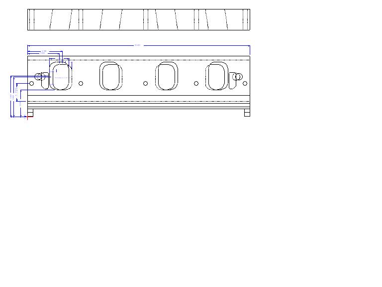
From the drawing you can see the angled ports. One way to machine these would be to angle the plates on the mill and then just cut a pocket, but there are some subtle curves in the roof and side of the port that I wanted to put in, so this wasn't the ideal solution. I thought the best way would be to use a special cutting tool, like what you see the CNC head porting guys use, so I could just outline the shape I wanted in 1/8" cross sectional increments and then cut them with the CNC porting cutter.
I found an outfit in Michigan that would manufacture the cutting tool I wanted. This is definitely the coolest cutter I've ever had:

The ball on the end is 1" in diameter, and the shank is necked down to 3/8" behind the ball, giving me the ability to cut around a corner up to 5/16". They sure didn't give this piece away at $230, but it is a carbide cutter that the manufacturer will resharpen when required, so I'm thinking of it as an investment

Last week I purchased the 2" X 6" 6061 aluminum bar that I needed to build the port plates. (They didn't exactly give this stuff away either LOL!) I bought enough so that I would have an extra 6" section that I could use to practice on, to get all the machining operations around one of the ports set up. After I had this piece right I could just copy and mirror the program to do the complete port plate.
I started off drilling the intake bolt holes and a guide hole for the water jacket passage, and then milled a pocket straight down to start the port. Here's a picture of the plate on the mill:

Next I chucked up my new cutter and spent quite a bit of time programming all the different passes. There were a total of 17 different outlines that I had to program, but many of them were similar, and I had done the curve work in Excel and generated a list of all the key coordinates that the CNC tool would require there, so most of the programming was just keying in the numbers. After double checking the whole program, I started up the machine. Here's a shot of the test plate after the first of the 17 outlines has been cut:

I stopped the program at this point to check some measurements, but everything looked good, so I let 'er rip. When the whole port was done it looked like a CNC'd cylinder head port, and I was really pleased with the result.
Next machining step was to set the plate up on a 45 degree angle and cut the bottom of the plate where it will meet the valley plate and end walls of the intake. The setup presented some indexing challenges, but nothing too difficult. Here's a picture of the plate on the 45 degree angle table, with the steps in the plate being milled:

The angle milling had to be done on both sides of the plate, and then I chucked it back in the vise to do some of the inital edge milling. I finally finished this up tonight; here's a picture of the partially finished plate:

Here's a couple more shots of it installed on the engine at cylinder #1:
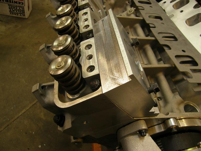
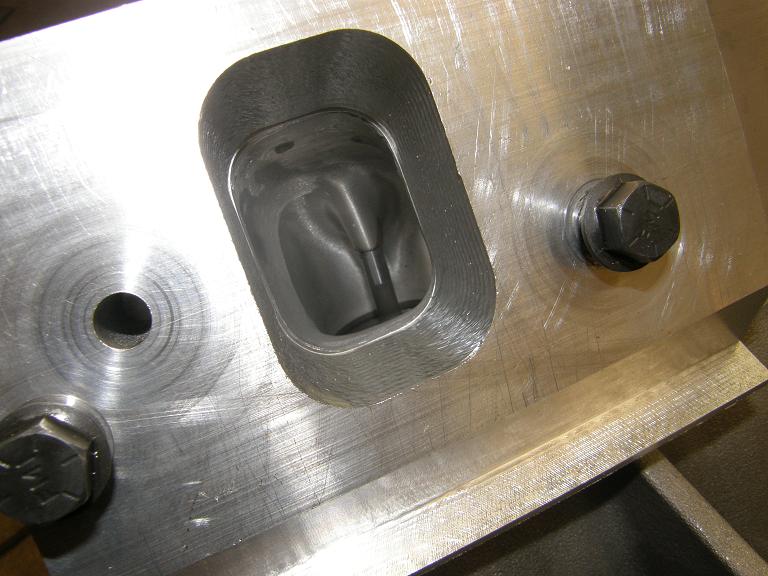
Looking down into the port in the photo above, I like the idea that I can get a sand roll in there before I build the rest of the intake, to get a perfect alignment between each port and the port plate. I just have to pull the heads and bolt on the plates, and I can get a perfect port match.
Next steps on this test piece will be to mark the pushrod locations and then program the mill to machine those. After that I'll have to tilt the test plate at a 4 degree angle in order to machine the valve cover rail, and then it will be time to remove as much extraneous material as possible from the plates, to lighten them up. Once that is finished I can start on the real plates by applying the CNC programs I developed on the test piece. Hopefully within the next few weeks I'll have these plates finished up, and can start on the runners and plenum of the intake. I'll post more info as soon as I have some significant progress to report - Jay


