Its been another eventful week on the cylinder head project. Last Tuesday I got the first castings for the individual runner intake manifold back from heat treat. Here's a picture of one as I received it:

Prior to getting the castings I had already machined a couple of additional blocks that were needed for my fixture, in order to raise the castings up high enough to try to machine them as completely as possible. I bolted those blocks onto the fixture and then clamped the first IR intake casting in place:

One thing about this particular casting is that it is very tall, and kind of spindly as you can see, so I ended up having to go really slow with all the machining operations, to avoid vibrations that hurt the finish on the part. This was particularly problematic in the throttle bore area, where I wanted a very smooth finish to ensure sealing of the butterfly against the casting. In the end, I made another additional part for the fixture to clamp the casting in the center of the bar, between the second and third runners, to help stabilize it. The picture below shows a machining operation with the casting tipped up on end, showing how the throttle bore is machined. Also note that there isn't a lot of clearance between some of the tools and the casting, particularly when machining the third and fourth runners. I had to play a lot of games with the CNC program to make sure that I didn't crash any tools into the casting during the machining operations.
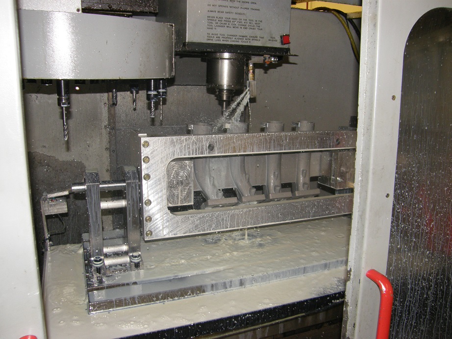
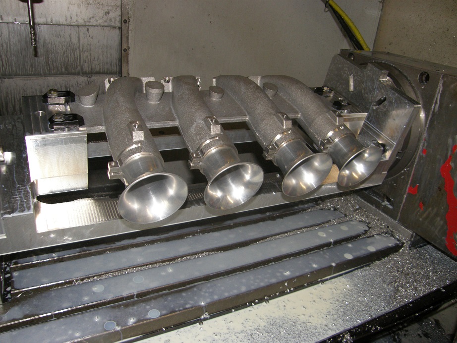
I worked on this all day Wednesday, Thursday, and Friday last week, and finally had the machining programs written and the casting successfully machined (with a couple of minor errors, as usual) through the first machining setup. Here's a picture of it on the machine; I added in the velocity stacks just because I wanted to see how they fit, and what the whole thing looked like:
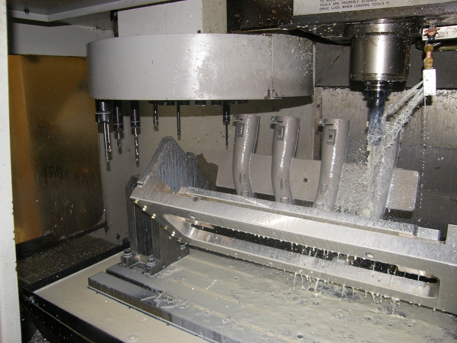
The second setup required another added fixture on the base fixture, so that the runners would bolt to the fixture using the holes machined in the first setup. This was necessary in order to cut the bar that connects the four runners together, and also to machine the EFI bungs and the pipe thread for vacuum fittings on the underside of each runner. Here's a shot of the casting bolted onto the additional fixture:

Once again in this configuration, clearance to the very long tools required for the machining, and even to the tool carousel itself, was limited, but by mid afternoon on Sunday I had this work all done.
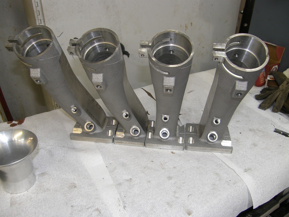
I just completed the hardest and most math intensive machining operations tonight. This was cutting down the sides of the runners so that they would fit together when bolted to the intake adapter. This was necessary because of some basic casting parameters. In order to get a good casting, you need a minimum metal thickness in all areas. When I designed this individual runner intake I started with the core of each runner, because I wanted to be able to increase the area from the port up to each throttle butterfly in a uniform fashion. This accelerates the air smoothly into the port for a good velocity characteristic. My foundry said that they would prefer to see at least 1/4" minimum wall thickness on these castings, because they are very long. However, when I added 1/4" of material to the core of each runner, the castings would have overlapped when bolted to the intake adapter; basically, they just wouldn't fit. In order to make it work I would have to either redesign the core and spread the runners out more, or machine the sides of the finished castings down to about 0.150" so that there was some minimal clearance between them. I elected to do the machining, since I was pretty happy with the core design. The picture below shows the sides of the runners after they have been machined to provide this clearance. The machining required me to generate a bunch of toolpaths using compound curves, which is quite time consuming, but after about 2-1/2 solid days on this I got it finished up. Again there were a couple of minor machining errors, but I was able to catch them before any drastic damage occurred to the casting. So, as is these runners are usable:

Here are the runners unbolted from the fixture; I'm machining the other casting now, and am looking forward to putting this together on the intake adapter this coming weekend.
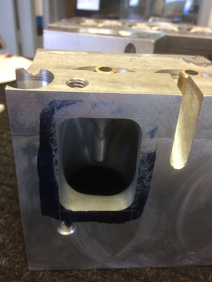
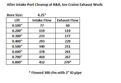
Also I got some very good news last week and Monday, regarding flow data on the cylinder heads. I had sent Joe Craine a chunk of one head to play with, and also given another chunk to my local porting guy. Joe really went to town on the exhaust side of the head I sent him, filling part of it with epoxy to actually decrease the outlet side of the port, and widening it up at the bottom. Joe's work increased the maximum port flow from 235 to 270 cfm, and when he installed a pipe with a 2" inside diameter the exhaust flow jumped to 300 cfm at 0.800" lift! A huge, huge improvement from where the port was, and I will be incorporating Joe's changes into the port design for the next set of castings. Also, I stopped by R&R Performance on Monday to pick up the remaining cylinder head, which my friend Bryan had installed seats and guides in, and done a valve job on. He had also played with the head chunk that I had given him a couple weeks back, focusing on the intake, and with a cartridge roll cleanup of the port, and squaring up the port opening, peak flow at 0.800" increased to 432 cfm. Most of the lower lift numbers remained the same. Here are pictures of the two chunks, the first one showing Bryan's work on the intake port, and the second one showing Joe's exhaust port. These are cell phone photos so they aren't the greatest, but you will get the idea:

Finally, here are the latest flow numbers:
Of course, now that I only have one runnable head, I will have to wait for another casting to try these out on an engine. Also, since I'll be making some changes to the port cores, and also the water jacket core, I'll probably just wait until I have a pair of the new castings before I run them on the dyno mule. Besides, I need to get new pistons for that engine to match up with the valve location on my heads, so that will take some time also. In the meantime, the 3D printed sand for the single 4 intake manifold should be at the foundry later this week. I'm hoping I can get it cast and then machined in time to bring it to the FE Reunion, along with the IR intake setup. We'll see...


