Show Posts

This section allows you to view all posts made by this member. Note that you can only see posts made in areas you currently have access to.


Messages - jayb

Pages: 1 2 3 [4] 5 6 ... 494
46
FE Technical Forum / Re: CVR water pump dimensions
« on: December 28, 2023, 09:46:33 PM »
Harry, the nose of the water pump motor is almost identical in position to the nose of the stock FE water pump; they both stick out about the same amount from the block.  Diameter of the CVR motor is 4".

47
I worked with a guy at Whipple several times, trying to get one of their superchargers to work with one of my intake adapters; I thought that would be a pretty cool option.  One issue is to really do it right, you need an intercooler installed below the supercharger.  That led to some pretty cramped spacing that we didn't think would work.  Along with that you have the issue of the belt getting in the way of the stock FE distributor (which would be solved with a crank trigger, coil pack ignition, feeding the charge in from the rear (ducting gets in the way of the shock towers and export brace on a Mustang/Fairlane), injector position and plumbing, etc.  If you went to a dedicated manifold for the Whipple, you could raise up the supercharger enough to make the intercooler work, which is the major hurdle, but that would be a low volume and expensive casting that would stick through the hood, if you could even find a foundry that would do it.  Raising it to stick through the hood kind of defeats the purpose, IMO.  Anyway, it is not an easy problem, but could be done with the right custom parts.

48
I think that is my trigger wheel on there, and my sensor bracket in the first picture.  The Innovator's West unit is nice if you have to reposition the sensor for fit reasons, and it adds some bling too.  Of course, EFI software allows you to change the actual trigger point of the sensor, so a fixed bracket will always work, as long as it fits in the engine compartment.

49
Non-FE Discussion Forum / Calliope Engine Project
« on: December 21, 2023, 03:36:48 PM »
Here's a couple pictures of one of the coolest engines Ford ever built:


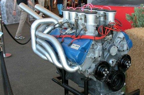
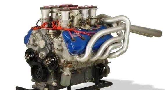
For those who don't know anything about this engine, here's a little background.  After winning LeMans in 1966 and 1967 in GT-40s with FE 427 engines, Ford was planning to go back to LeMans in 1968 with a new engine.  This engine was very loosely based on the new for '68 385 series engine, but had dramatic engineering changes compared to the production engine.  The engine had 2 intake valves and one exhaust valve per cylinder, and the valves were pushrod actuated with two different camshafts in the block, one cam with 16 lobes in the normal position to run the 16 intake rockers, and a second cam in the block above the first which ran the 8 exhaust rockers.  The exhaust pushrods ran horizontally from the cam to the exhaust rockers.   

Built into the cylinder heads were the injector stacks, so that no traditional intake manifold would be required.  The presence of the stacks apparently reminded Ford engineers of a calliope pipe organ, which is how the engine got it's nickname.  The bundle of snakes headers shown in the pictures were designed to fit the Ford GT-40 Mk IV chassis.  The engine also featured a dry sump system incorporated in the pan, which was claimed to provide crankcase vacuum in addition to oil pressure and control. 

The engine was 427 cubic inches in order to meet LeMans rules, but prior to the 1968 LeMans race, the sanctioning body outlawed 7 liter engines, making smaller engines mandatory.  As a result the project was stillborn after the rule change, and Ford corporate bailed on racing at LeMans (although independent teams won again with GT-40s in 1968 and 1969, running small blocks).  The Calliope engine itself disappeared from view for many years.  Apparently only two of the engines were produced, and only one is still existing, at the Ford museum in Dearborn.  Dyno testing by Ford back in the day showed the engine delivered 630 HP, which would have been a big step up in the LeMans cars compared to the FE engine.

My friend Dan Schoneck learned about the Calliope engine a few years ago and after asking a bunch of questions of various contacts, found out that the original foundry tooling for the engine was still in existence.  From what I understand the tooling originally went to Holman and Moody, and then was sold to a well known parts manufacturer on the west coast in the 1980s.  I don't have permission to reveal who had the tooling, but most of us would know his company.  In any case, Dan finally found out who had the tooling, and arranged to buy it all; he came back with it this past summer. 

Over the last 12 years I've developed a lot of foundry experience and tooling contacts, and this was one project I was very interested in getting involved in.  So after getting a look at the tooling Dan brought back, and figuring out what we had, I volunteered to bring it to my foundry's attention and see if they would be interested in casting it.  This was a bit of a sales job, because the volumes of this project were not going to be high, and working with tooling from the 1960s would certainly be a little risky, but I put together a presentation for the foundry and they were interested enough to give us the go ahead for casting the cylinder heads.  I also got my local pattern shop involved, because I know the owner there very well and he loves doing this kind of stuff.  The owner has years of experience designing the feed system which channels aluminum into the mold properly.  This is a critical part of any aluminum casting and was going to be required because the tooling was prototype tooling from Ford, and did not have sprues, risers, gating, or any feed system that normal foundry tooling has.  This meant that Ford originally cut all these features into the sand cores by hand.  My pattern guy has the experience to do the same thing, so he is an important part of the project.

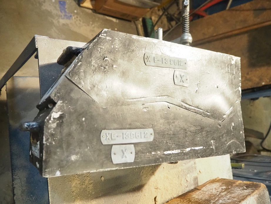
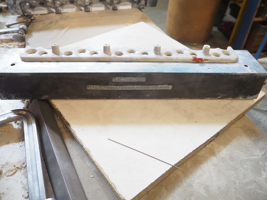
Dan delivered the tooling to the foundry a couple weeks ago, and yesterday we got started on trying to pour a cylinder head.  The Ford tooling is super cool; most of it is hand made from mahogany, and each tooling box is labeled with a Ford XE number.  Apparently the XE number for the Ford Calliope cylinder head is XE-139612.  See the tags on the cylinder head end core box below.


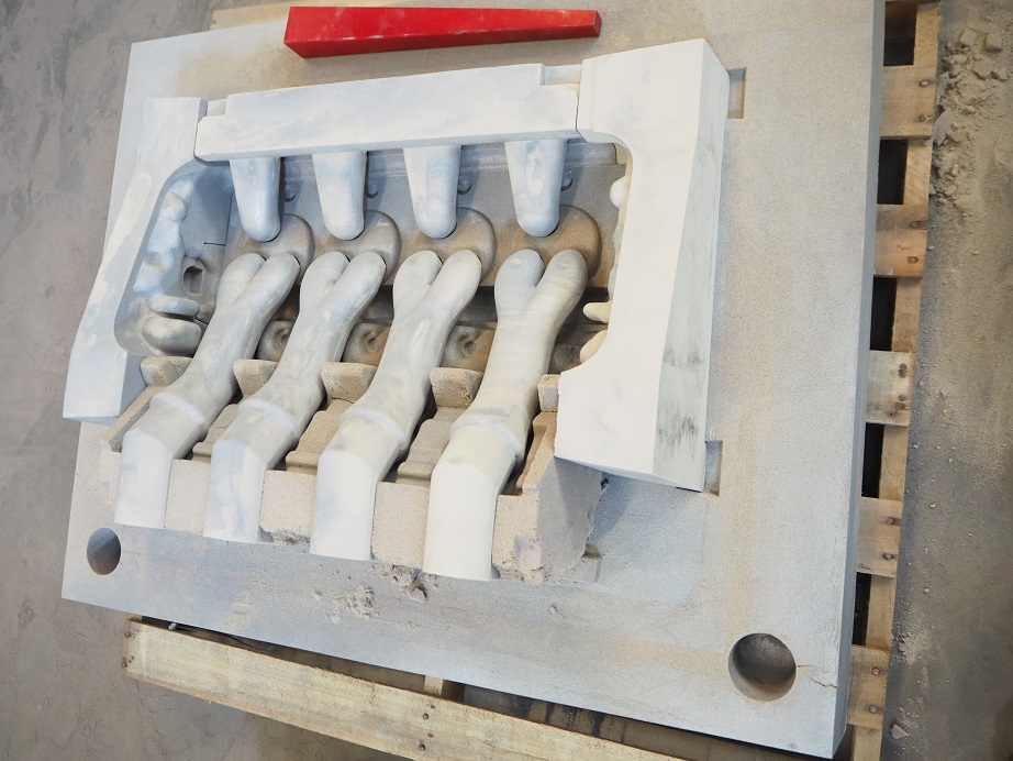
Pictures of some of the sand molds are below.  This is the drag, which is the bottom of the mold:


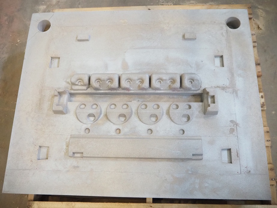
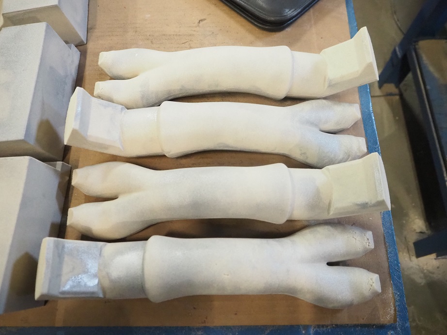
The intake port cores are individual, and look like this:


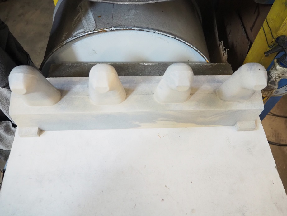
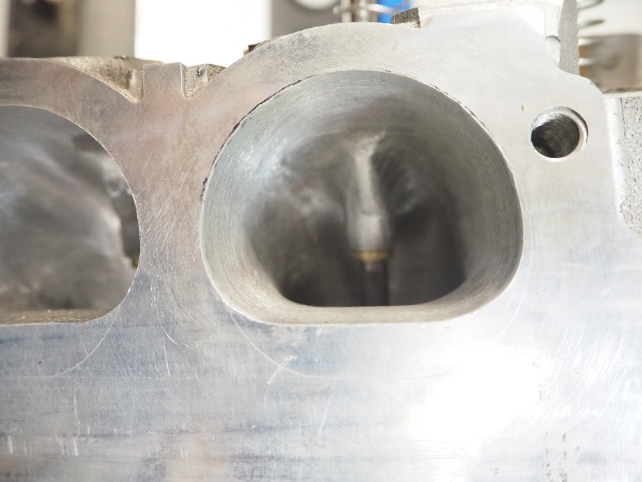
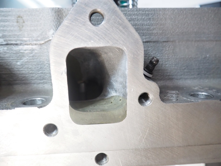
The exhaust ports cores are all molded in a single piece.  It's interesting to see how the port widens out into an oval shape as it exits the head:


There are also cores for each end of the cylinder head, and the bottom of the intake runners.  We assembled all these parts on the drag to get a look at how it all fits together:


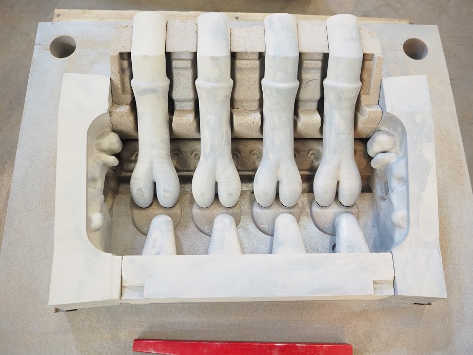
The core below closes over the top of the previous mold:


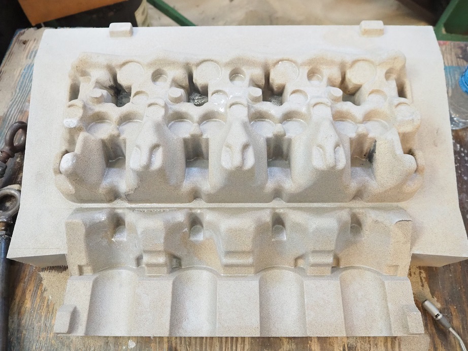
Then the cope, which is the top of the mold, is installed and the mold is ready for pouring.  Unfortunately, we ran into a problem with the Ford tooling when it came to the water jacket core.  This is a very complex set of three cores, with sand thicknesses down to around 0.100".  The foundry guys had trouble getting the sand packed into these molds by hand; our guess is that Ford had a machine to do that, which the foundry doesn't have.  Also, even if the mold got completely filled, there was difficulty getting the cores out of the molds without breaking them.  Pictures of the core box for the lower water jacket core is below, the second one showing the sand after the box was split back apart after filling.  In the second picture we are using glue to hold the sand core together after it broke coming out of the mold.


There are three water jacket cores like this, that need to be glued together and then set into the mold.  After spending hours just trying to get a good one, I suggested that we go to a 3D printed version, and make it a single core.  We are lucky that Dan has the masters for these cores (the masters are what the 3 finished cores are supposed to look like).  Dan is going to get them 3D scanned so that we have a file showing what the completed water jacket core is supposed to look like, and then we can get them printed in sand so that we don't have to fight with getting decent cores out of the Ford tooling.

Due to the issues with the water jacket we didn't get to pour a head yet.  Hopefully in a month we will be back at the foundry with water jacket cores so we can get some of these poured.  Of course, getting good castings is just the beginning of the work.  Next they need to be machined, which means machining fixtures will have to be made, and there will be some guessing on the where all the surfaces and holes need to be, because we don't have blueprints for the engine.  However, Dan has arranged with the Ford museum to be there and get a detailed look at the engine that they do have, so hopefully that will point us in the right direction.

The block is also going to be an issue, because a standard 429/460 block is nowhere near close to working.  The Calliope engine used Cooper rings for sealing the head to the block, and has no provision for water passages from the block to the head; instead, the water from the dual water pumps flows through the block to the back, makes a U-turn into the head at the back via an external fitting, and flows out of the front of the head.  Also, the head bolt locations are completely different; there are actually 8 bolts around each cylinder on the Calliope engine, and none of them are in the normal head bolt position in the block.  On top of all that, Dan is missing some tooling for the block, and we will have to go to a different foundry for the block because the foundry we are using can't pour a part as large as an engine block.  So, basically this is the beginning of a fairly long project, but Dan is committed to getting it done.  For my part, I just want to see one of these things running on the dyno ;-)

I will post updates on this project as they happen - Jay

50
FE Technical Forum / Re: CVR Water pump inlet tubes
« on: December 15, 2023, 10:01:29 PM »
Bob, have you tried going directly to CVR?  Link below...

http://www.cvrproducts.com/product-category/proflo-accessories/billet-inlet-fittings/

51
FE Technical Forum / Re: FE Power Tunnel Port Cylinder Heads
« on: December 12, 2023, 03:46:21 PM »
So a while back I sent my first prototype tunnel port head to Joe Craine, who had generously offered to port it for me to see what he could get out of it.  Joe only worked on the ports in one chamber on the intake, and only finished one chamber on the exhaust, but he was able to come up with some pretty good numbers:

Lift            Intake       Exhaust (no pipe)
.100"          78             58
.200"         155          114
.300"         227          141
.400"         285          192
.500"         330          212
.600"         357          219
.700"         379          222
.800"         390          230  (260 with pipe)

On the exhaust side, Joe flowed most of the lifts with no pipe, and as seen at the .800" lift level, the pipe definitely helps.  My local shop that flowed these heads always uses a pipe on the exhaust, so Joe's numbers are very impressive if that is taken into consideration.  Joe also experimented with adding some epoxy to the floor of the exhaust port, which apparently hurt some at first but flow later came back with some more massaging.

Also I really liked Joe's intake port treatment.  He did not do any significant enlarging of the port, which is great from a velocity standpoint. The improvements he made picked up 40 cfm from the as-cast numbers that I posted previously.  Joe commented that with more work he felt that 400 cfm is easily possible with these heads.

Joe also did some work in the chamber to open up the flow around the valves; it appears from my measurements that he went up to a 4.31 bore size.  This certainly helped the flow as well.  Bigger bores are always better for breathing.

Here are some pics of the intake and exhaust port.  I'm sure if anyone has questions about his work Joe will be happy to chime in and answer - Jay


52
Non-FE Discussion Forum / Re: Need heads ported in Minnesota
« on: December 08, 2023, 09:54:46 AM »
+1 on both Bryan and Jason, they both do a very good job.

53
FE Technical Forum / Re: Valve to piston clearance question
« on: December 06, 2023, 09:49:30 AM »
On my big SOHC I ran .050" and still saw those witness marks.  Bigger is better IMO...

54
FE Technical Forum / Re: Throttle body options
« on: November 29, 2023, 10:36:14 AM »
The Holley throttle bodies are nice because they include the TPS and IAC, and I think they also have the ATS if I recall correctly.  Plus they bolt onto an intake with a 4150 flange. 

https://www.summitracing.com/parts/hly-112-588

55
Vendor Classifieds / Re: FE Power Tunnel Port Cylinder Heads
« on: November 24, 2023, 12:15:04 PM »
Joe, the first production batch is all spoken for, but I expect to run another production batch in the spring, and hopefully have some that people can buy right off the shelf.  We will see how that turns out.  Naturally ( ::)), the prototype castings with the SE exhaust ports had an issue completely filling the mold, and the foundry is adjusting their process to solve the problem.  So right off the bat I'm a month behind from the original schedule.  None of this stuff is easy...

56
Happy Thanksgiving to all my pals on the FE Power forums!

57
FE Technical Forum / Re: big ,med, or small block
« on: November 24, 2023, 11:00:04 AM »
Ford always referred to the FE as a big block back in the 1960s.  They were facing advertising from competitors which called their engines big blocks, and if they started calling the FE a "medium block", they would have looked like they weren't keeping up with the competition.  Pontiac called their engines big blocks and they are dimensionally very similar to an FE.  Calling an FE a medium block is stupid, IMO.

Also, despite what people may or may not have heard, Ford was referring to the engine as an FE back in the early 1960s.  See the Ford memo below - Jay


58
FE Technical Forum / Re: 511ci FE w/ FE Power Cylinder Heads
« on: November 21, 2023, 05:27:03 PM »
You have actually hit on one of the reasons why I did these heads.  I wanted to be able to build a 600+HP 390 stroker engine with a very mild cam.  I've got one here that I just haven't put together yet, but when I get a chance to do it I plan to start with a fairly strong cam, and then back the cam down in steps to see just how small I can go and still make 600 HP.  Should be fun, and hopefully eye opening...

59
FE Technical Forum / Re: 511ci FE w/ FE Power Cylinder Heads
« on: November 20, 2023, 06:40:02 PM »
Hey Brent, nice job on the build. Sorry to hear the customer has ghosted you. Hopfuly he will be in touch with you soon.
Was wondering if it looked like there would be any possibility to run a 1/2" pushrod on the intake side as well with some doable modifications ? I'll be running some monster spring pressure's and had hoped to be able to use 1/2" dbl tapered across the board.  Haven't made it that far with mock up yet, Haven't even had the engine unwrapped in a month or so due to my work schedule as of late but will be back on it soon as I got some off time built up for the holidays.

Keith, I think a 1/2" intake pushrod with your intake adapter will be pretty tight.  I may have a solution though.  One of the things I discovered, with the help of one of my customers, is that when running a hydraulic roller lifter there was not enough pushrod clearance on the intake side.  This is because the pushrod seat in the hydraulic roller lifters is about half an inch higher than the pushrod seat on a solid roller or flat tappet lifter.  This put a little more angle on the intake pushrod, and caused an interference issue.

As a result of this I've designed a different port configuration on the intake adapter for hydraulic roller applications.  The ports feature a small bump in the interior where the intake pushrod goes by, with a correspondingly deeper cut outside of the port for more pushrod clearance. 

There's no reason that you couldn't use one of these intake adapters, which would provide additional clearance for 1/2" pushrods.  The only downside is that the bumps on the interior of the ports reduce the port cross section in that area.  Of course you would rather not have that, but its not a big difference from the standard intake adapters and you may want to consider it a tradeoff, depending on how important you think the larger diameter pushrod is.

Hope that helps - Jay

60
FE Technical Forum / Re: Steve Morris Engines Cammer build.
« on: November 17, 2023, 01:58:16 PM »
Looking at the pictures I think the cams are OK.  Notice the one cam has the lobes almost 180 degrees apart, and the other has them close together.  That is what SOHC cams look like.  His problem is the length of the valves, and what he perceives the problem is with the elephant foot adjuster scrubbing over the top of the valve.  He claims this is going to break parts.  It's not, at least in a drag application.  I've run those adjusters to 7800 many, many times.  The problem comes with sustained high RPM over 10-15 seconds, as Bill's videos show.  On the dyno, or at the drag strip, the elephant foot adjusters are not an issue.

Pages: 1 2 3 [4] 5 6 ... 494