It's been mid winter since I've run the dyno mule with my cylinder heads, and despite having several tests that I've needed to run, work on getting the head package into production has taken a bunch of time so I didn't get back at the dyno testing until this week. All along my friend Royce B has been mercilessly hounding me to get back on the dyno LOL! Royce is a dyno junkie, and wanted to come up to help. Finally on Wednesday this week my schedule opened up, Royce arrived and we got going again with the testing.
It had been quite a while since the last test, so the first order of business was to baseline the dyno mule again. The unported SE cylinder heads and the 8V intake with two Dominator carbs were on the engine, and the cam was still the same cam Brent Lykins got for me last winter. Previous best was 861 HP with this combination. After debugging an electrical problem we got the engine running correctly, and I was happy to see some even better results; the engine peaked at 869 HP and 730 lb-ft of torque.

Later during the analysis I discovered that I had left the RE timing spec in the EFI software, which was 30 degrees total instead of 28 degrees total as I had originally run with the SE heads. So that little tweak to the timing probably explains the slight improvement. Nevertheless, we were back to baseline and ready for more testing.
Over the last several months I've been designing some new intake manifolds to use with my heads. I'm actually quite happy with the performance of the 4V intake, but the 8V intake isn't working as well as I'd hoped. I tried to design the 8V intake as something similar to the tunnel wedge for use with my heads, but in the quest for power I kept the runners straight, and it ended up not looking like a tunnel wedge manifold at all, and not having the plenum volume and design of a modern sheet metal style intake either. So I went back to the drawing board and the 3D printer, and ended up designing two more 8V intakes in the more traditional sheet metal style. Also, in speaking with a few of my cylinder head customers, some of them had hood clearance concerns, so I elected to do an 8V intake design that was lower, and did look like a traditional tunnel wedge manifold. Finally, I also wanted to do a lower 4V intake, and after making some measurements I concluded that using a low profile EFI throttle body, I could actually make the intake work with a shaker or ram air setup.
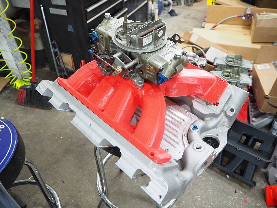
My 3D printer has been balky over the last few months, and I've had to make some repairs and part replacements to keep it running properly, but after a few false starts I finally got all four of these intakes printed. This is the low version of the 4V intake, sitting on an intake adapter:
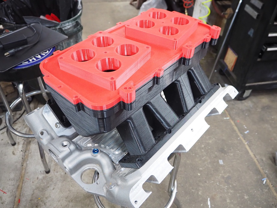
The photo below is the low version of the 8V intake, designed in the tunnel wedge style:

This one is one version of a sheet metal style intake, with short runners and a lot of taper:
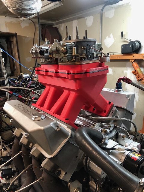
This is the other version of a sheet metal style intake; this one has longer runners and less taper, and is shown mounted on the engine:
I've been thinking about running these plastic manifolds on the dyno for a while, and one concern was if they were going to be airtight or not. Before the dyno session I had briefly considered painting them all to try to make sure that the external surfaces were all leak free, but I didn't get around to that before the dyno session, so I decided to just bolt on the red sheet metal style manifold and try to run it. Unfortunately, when we started the engine it was obvious that there was a big vacuum leak, and a few seconds after starting the engine, it backfired and broke the plastic manifold. So, it was clear that some sort of sealing on the external surfaces of the 3D printed intakes was going to be required. The joys of R&D...
At that point we decided to swap over to the RE heads. We had not yet tested the RE heads with the Lykins cam, and since that cam had picked up the engine with the SE heads substantially, I was anxious to see how it would improve the performance with the RE heads. Pretty much all day Thursday was devoted to the swap, since in addition to just changing the heads, all the valves and springs had to be swapped from the SE heads to the RE heads also. We finally got the engine all back together with the 8V intake at the end of the day on Thursday, and started it up to make sure that everything was OK. The engine sounded good, so we were primed for a good dyno session on Friday.
Friday's dyno session did not disappoint. After a couple of checkout pulls, we ran the engine to 7000 RPM, and much to my surprise, it appeared to be still climbing in power at that point. I really didn't want to run past 7000 with the RPM crank that is in the engine, but we decided to make a 5300-7300 RPM pull and see what happened. We were rewarded with just over 881 HP, and again the engine still appeared to be climbing at 7300 RPM:

Next step would have been running to 7500 RPM, but as the engine came out of the pull on the previous run, Royce and I thought there may have been some valvetrain noise. So out of an abundance of caution we decided to pull the valve covers and check the lash. Sure enough, the #6 exhaust lash had increased from .016" to .030", and that was probably what we had been hearing. We immediately suspected a lifter was going away; the Crower roller lifters I've had in this dyno mule have been around for a while and used in different engines, and we've had to replace a few of them during the course of this testing. So, reluctantly we pulled the intake and carbs, and opened up the plate in the middle of the intake adapter so we could pull the #6 lifter. However, checking it there were no obvious problems. Next I disassembled the rocker arm pair from #6, and again everything looked fine. I don't have an explanation for the increased lash, unless I just didn't tighten the adjuster enough when I set it.
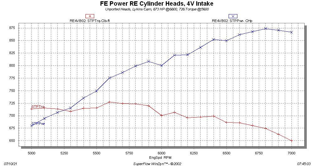
At this point we decided to just go to the 4V intake, since we were happy with the results of the 8V. We installed the 1150 Dominator carb on the intake, and ran again. Previous best with the old cam had been 857 HP, but the new cam bumped us up to 873 HP, and also a bit of a torque increase:
One thing about the 4V intake was that it did not appear to be making power all the way to 7000 RPM. In fact we ran two pulls to 7300 RPM, and in both cases the power did not increase, and in fact the engine seemed to miss a little past 7000 RPM. A look at the air inlet data gave a clue on this, as the engine was requiring very close to the 1150 cfm of air that the carb was rated for. We saw vacuum levels of as high as 1.6 inches with the 4V intake and carb, where vacuum levels for the 8V setup were zero through the whole RPM range. So obviously the engine liked the 8V setup better.
Thursday I had taken the time to paint the exterior of the remaining 3D printed intakes, to try to seal them up. The 8V tunnel wedge intake also had some gaps in the plastic that the paint wouldn't fill, so Royce took a caulk tube of The Right Stuff and attempted to seal up those holes. By the time he was done, he had slathered about 2/3 of the intake with that stuff LOL! It was ugly, but we hoped it would seal. We decided to do that intake next, so Friday afternoon we bolted it on the engine with two 660 center squirter carbs, and tried to run. But again, it was obvious that there was still a vacuum leak; the engine would burn through the pump shot and then die. We didn't want to risk breaking that intake with a backfire, so we stopped the testing.
As a final experiment with the plastic intakes, we took the low 4V intake and sealed up the carb pad with a plate, then taped off the runners on one side and filled the intake up with water. We were very surprised that despite being painted to seal it up, it was still leaking like a sieve. We had water dripping out of the bolt holes, the bottom of the plenum area, and some of the runners. So obviously just painting the intake with Rustoleum was not going to get it sealed. This week I'm going to be working on a better sealing procedure for the 3D printed intakes, and also a test rig so that I can test them for leakage with a few psi of air, prior to actually installing and running them on the engine. I'm sure that they can be run if I can fix the sealing issue, and it will be good data to have before deciding if I want to proceed in production with them or not.
Regardless of those issues, I'm very pleased with the power numbers from the existing 4V and 8V intakes. I'm close enough to 900 HP now that with some tweaks I'm sure I can reach that goal with this engine, which I think is pretty cool with heads where the ports are still rough cast. I'm not running much crankcase vacuum, only about 7", so I may increase that somewhat to pick up some power. Lykins thinks I should run some shear plates under the carbs, so I may try that. I may also try a bigger primary tube on the headers; I picked up substantial power going from 2" to 2-1/8", so it may be worth building a set of 2-1/4" headers just to test on the RE heads. When I have more data I will put it up here; I'm particularly looking forward to running the single piece crossram intake, which is ready to be cast as soon as the foundry can open up a slot to pour it. Stay tuned...


