So, I've been making a little more progress on the clear valve covers. The vacuum forming was the big thing, but I still had to design and machine rails to go around the outside of the valve cover, to seal the Lexan to the ring and have a rigid surface for sealing the whole valve cover assembly to the engine. Over the last couple of weeks I've managed to design and CNC the rails for one of these valve covers. My original plan had been to seal the Lexan to the aluminum with an O-ring, but with all the bolts required to hold the two halves of the aluminum rails together, there just didn't seem to be enough room for a decent O-ring, so I ended up using gray silicone to make the seal. I also designed the rails so that a strip of LED lights could fit in there, just for a little bling LOL! Actually, I'm thinking that under the hood at night, you won't be able to see anything through these covers unless there is some kind of light source, so I put the LEDs in there for that purpose. But if I had a Toyota and was a tuner, I'd be pretty excited about this...

After vacuum forming the first few covers I decided to make a change to the plug, to provide a flat surface on the top of the valve cover that I could mount an oil fill cap or breather on. I don't have the plug modification finished yet, and I was going to wait until I had that done before I put one of these things together, but this morning when I came out to the shop I thought what the hell, let's see what one of these things looks like. So, I took one of the Lexan covers I'd previously made and bolted one of the assemblies together. Here are some photos.
The photo below shows all the parts required to build a clear valve cover, including the aluminum rails and the strip of LEDs:
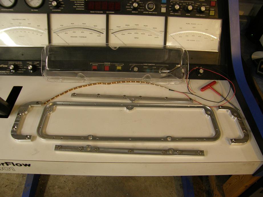
I was able to get this machined out of a 6" X 30" piece of 3/8" thick aluminum plate, because I broke up the top rail into four separate pieces. Otherwise, if I had made the two rails as single pieces, it would have taken a 45" length of aluminum to fit. The single piece shown in the photo is the bottom rail; I wanted it continuous so that I could get a good seal to the Lexan and also to the valve cover gasket, but the top parts are only required to sandwich the Lexan, so designing them as four different pieces wasn't a problem. Note the LED light strip, which was real convenient to use for this application. Unfortunately, it is not rated for anywhere near automotive temperatures, but we'll see how it does. I don't plan to drive around with the lights on or anything...
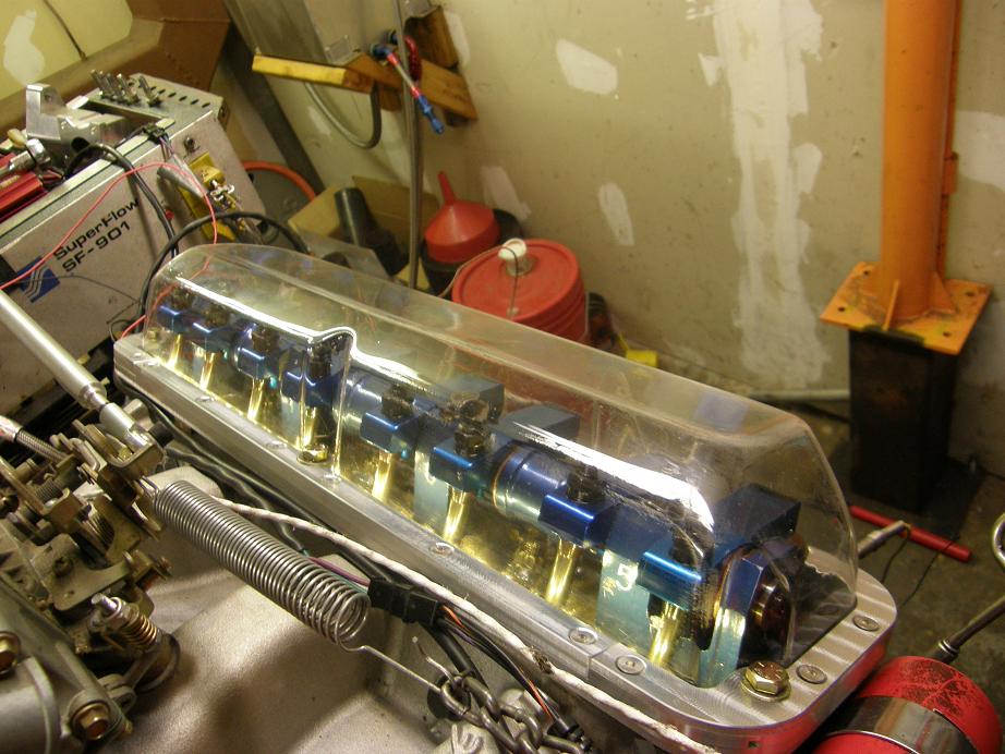
Here's a couple pictures of the completed unit:
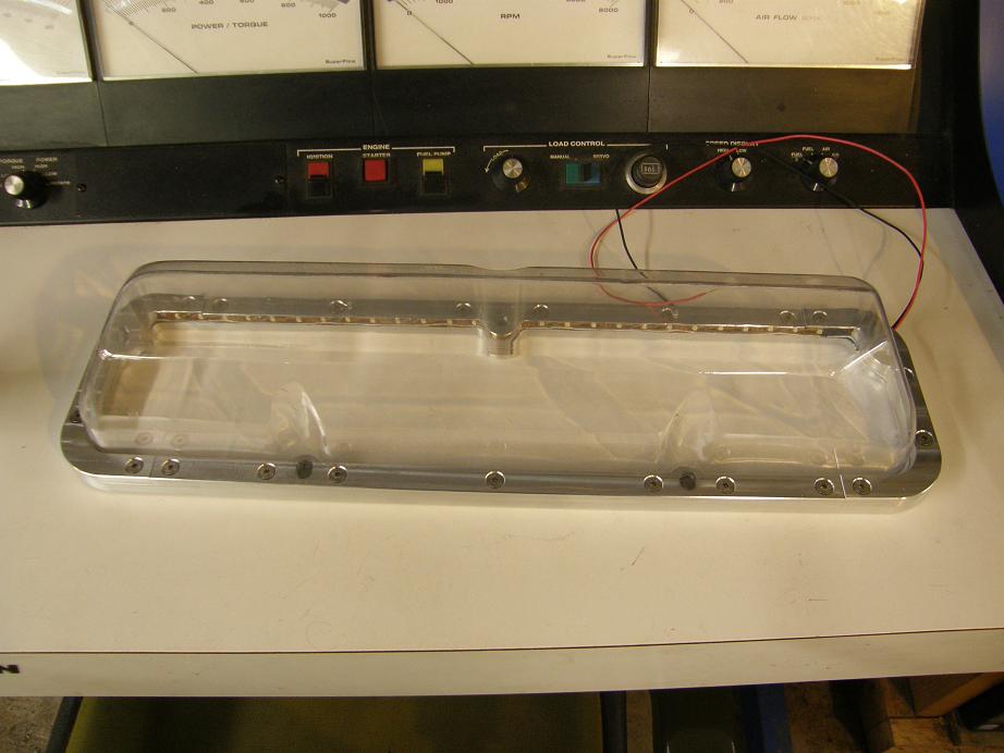
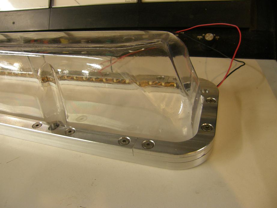
In the bottom photo you can see the LED strip positioned inside the top aluminum rail. The rail assembly is nice and rigid, and I don't expect any sealing problems.
After dummying this together (no sealer between the Lexan and the rail yet), I bolted it on the engine to see what it looked like. I had purchased two different colors of LED strips, white and green. (I had wanted blue, but Digikey was out of those.) Here's some photos of the valve cover installed, and with the white LEDs turned on:
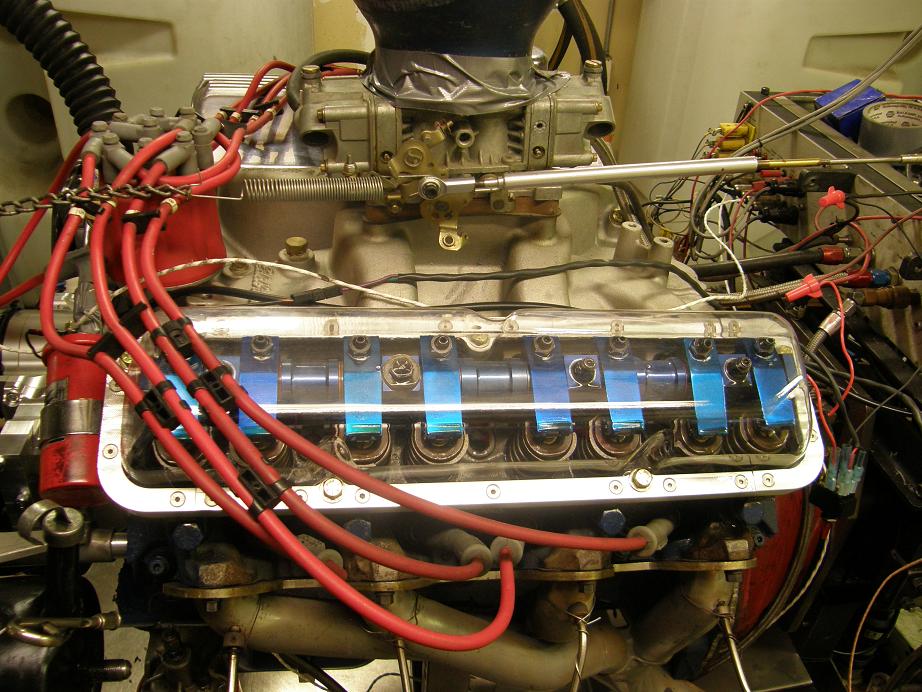
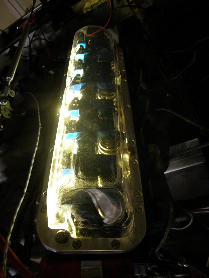
In the last photo I had decided to flip off the lights and take a picture with the LEDs turned on, but this didn't look so hot; you've got a good view of the pushrods, but the position of the LED strip in the valve cover rail doesn't really illuminate the rocker arms all that well. Next I tried the green LEDs:
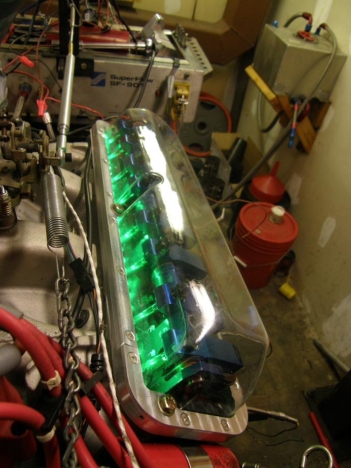
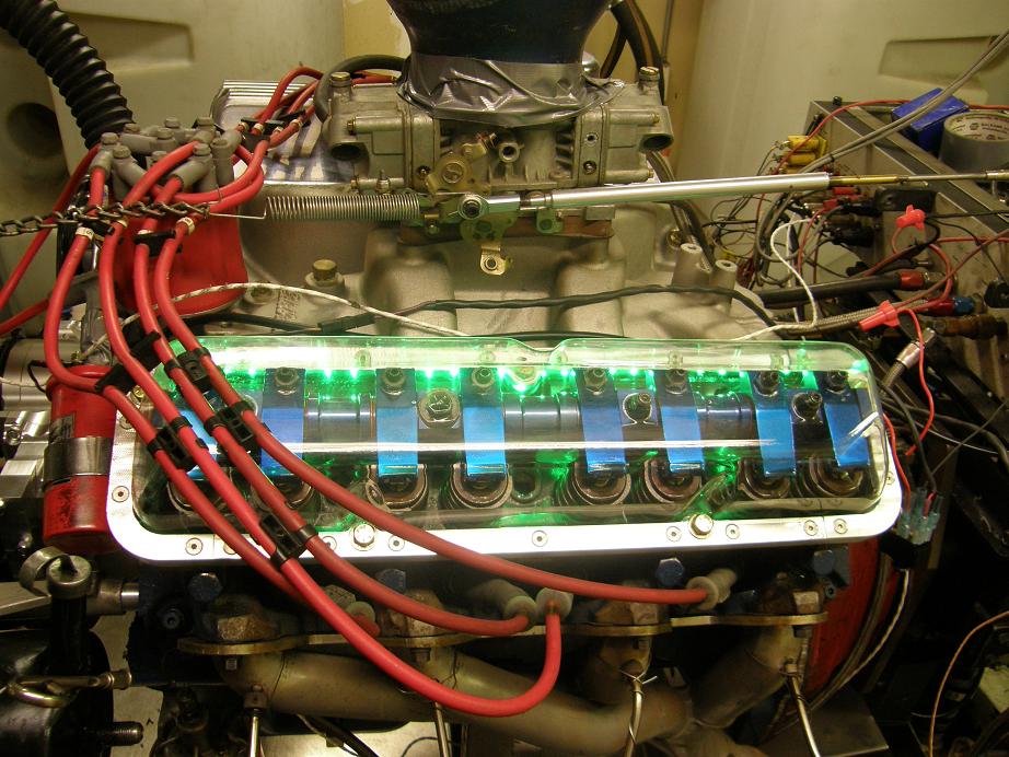
I decided I liked the green LEDs better, so I used those when I did the final assembly on the cover. Prior to final assembly I sanded the lower flange of the Lexan to give the silicone something to bite on, and then bolted it all together. Pretty straightforward, really. Next I re-installed the valve cover on the engine and tightened everything down this time. So, it was time for the moment of truth. When I fired up the engine I was concerned about leaks, but after watching it for several minutes none developed. So, I think I must have a good seal between the Lexan and the aluminum rail. I made a video of the engine cranking and then running with the valve cover in place, and found that after the engine was running the frame rate of my camera was such that around 1600 RPM the rocker arm movements appear to slow down, and you can see the rockers in motion. A link to the video is below:
http://youtu.be/mIl9DbAopyUI have to admit that I was kind of surprised at how little oil was splashing around under the valve cover. There was no problem making out what the valvetrain was doing. After making the video I continued to run the engine to warm it up, and then turned on the camera again to record a dyno pull. This time there was a little more oil splash, but still not enough to really occlude the valvetrain from view:
http://youtu.be/7wQsvOB4fJcAt this point, so far anyway, this project has been a success. Over the next few weeks I'll get a couple sets of these cranked out, equipped with breathers so that they can actually be used on the car. Then I'll try to get the engine installed in my 68 Mustang and see how these things hold up. I have to say I think they're kind of cool, and I'm hoping for success with the summer road test...

 Poll
Poll
