Show Posts

This section allows you to view all posts made by this member. Note that you can only see posts made in areas you currently have access to.


Messages - jayb

Pages: 1 ... 491 492 [493] 494
7381
I made more progress on the car this week, although I wasn't able to work on it for any more than a few hours at a time this week.  Fortunately, I had a couple of good weeknights where I made some progress, and I found some parts I'd been looking for, which made the work a little more productive.

On Monday night I was looking on ebay for the rear trim for a 69 Shelby, that goes on the trunk lid and quarter panel end caps.  This trim had been hard to find in the past, so I was surprised to see a company on ebay advertising parts for these cars, and they had the trim I was looking for.  They are some kind of a Shelby restoration outfit in Green Bay Wisconsin, and in addition to the rear trim items they also advertised the front bumper brackets that are specific to 69 Shelbys.  I had been planning on fabricating these brackets from stock Mustang parts, but this was going to take some time, and given that I'm always behind schedule on these projects, I figured it would be a plus if I could just buy the brackets and bolt them on.  So, Tuesday on my lunch break I gave the company a call and ordered the parts.

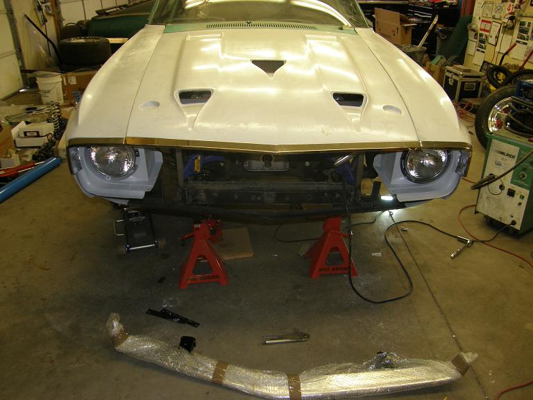
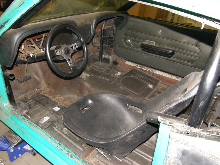
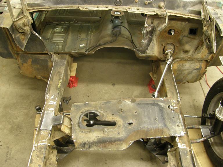
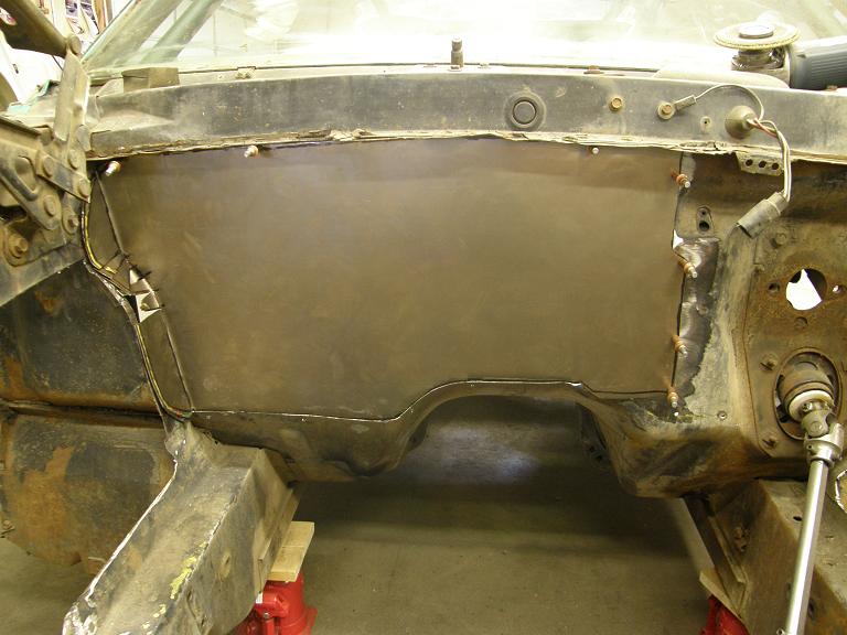
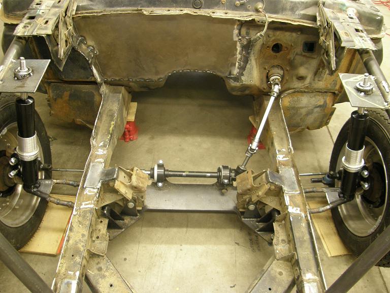
Tuesday night I had a free night out in the shop, so I continued working on getting the front end of the car put together.  I had to build some brackets to help hold the fiberglass fenders and headlight buckets in the correct position, and they had to be adjustable so I could twist the parts around and check the alignment, then move them again if they weren't right.  After a few hours on Tuesday night I finally had the brackets fabricated, and had the fender positioned so I could install the fiberglass panels that bridge the gap between the fenders at the front of the car.  The car looked a lot more complete with these panels in position.

Thursday my parts came, so I was back out in the shop Thursday night, and bolted on the front bumper brackets.  Unfortunately, the bumper wouldn't fit on the brackets, and after examining the situation a little I noticed that the problem was the driver's side front frame rail, which seemed to have a bow or pucker in the sheet metal that caused the driver's side bumper bracket to angle outboard a little, instead of coming straight out so it would align with the bumper.  A little work with a hammer and the torch resolved that issue, and I finally got the bumper installed after the modifications.  I spent the rest of the evening Thursday getting the grille trimmed so it would fit around the headlight rings and bolt into the correct position.

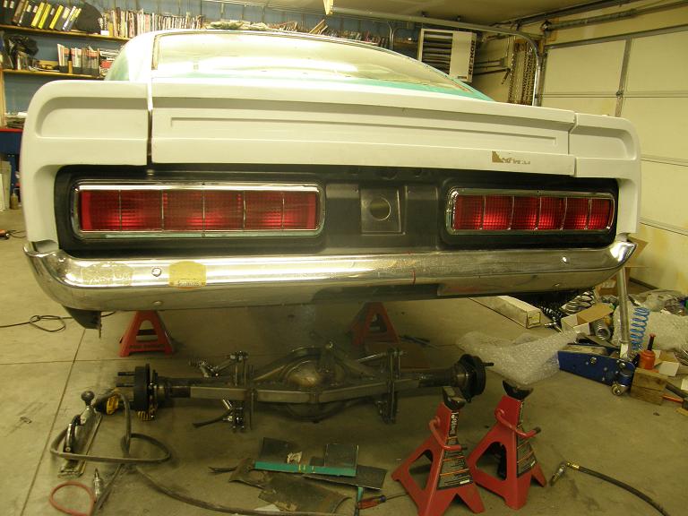
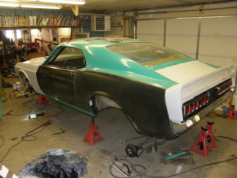
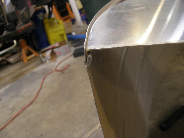
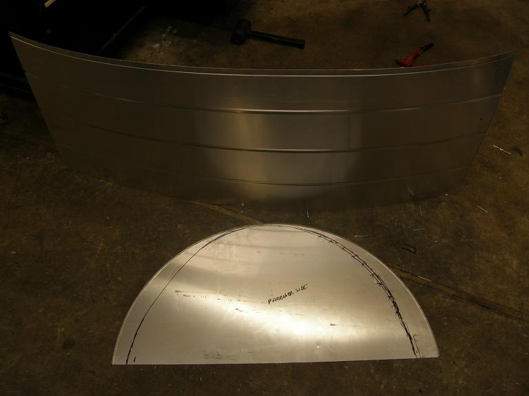
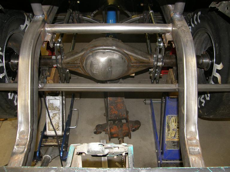
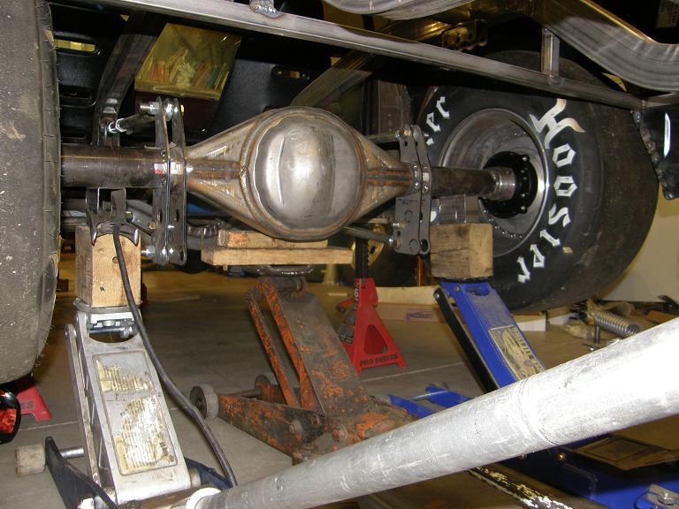
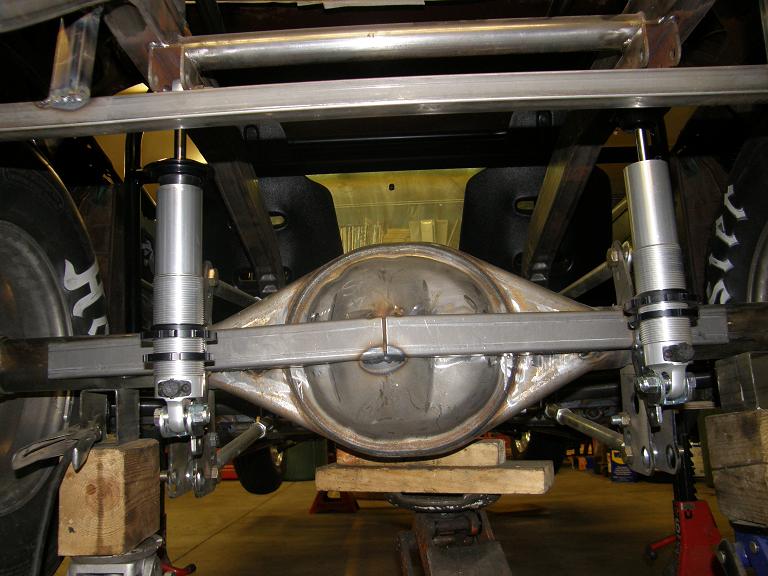
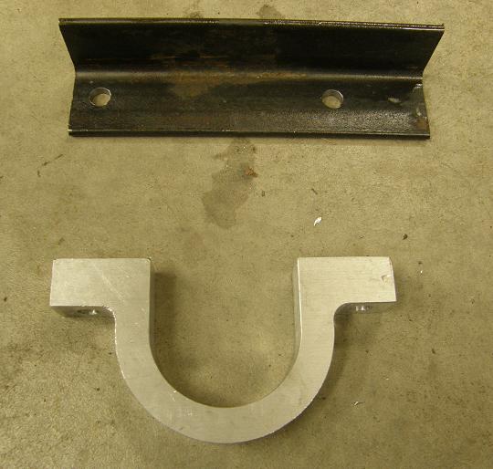
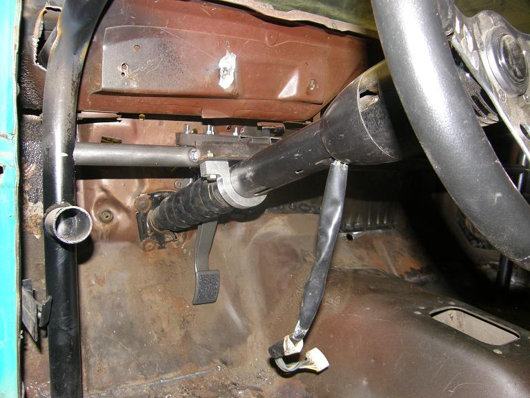
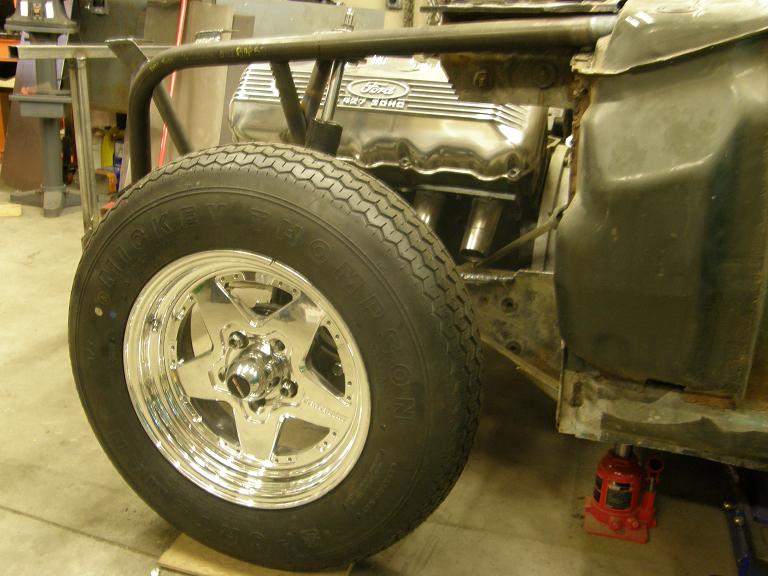
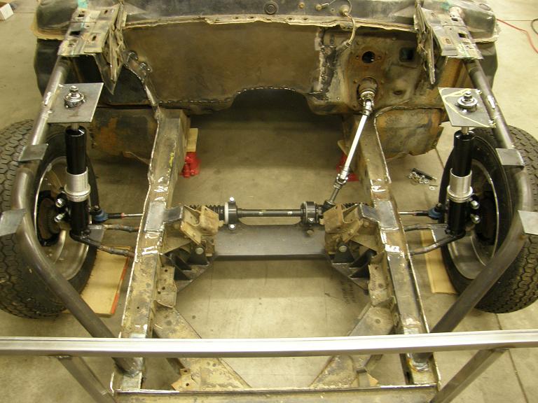
Finally on Friday night I worked on getting the hood hold downs installed.  The hood pins came with brackets that bolt onto the front fenders under the hood.  I cut the holes in the fiberglass hood, bolted on the hood pin brackets, closed the hood and looked through the holes, and saw they were misaligned by a good half inch.  Seems like every bit of this fiberglass related stuff has to be custom fit or modified in some way.  After screwing around with this for a while I finally concluded that the only way to make the hood pins fit into the brackets was to shorten the brackets, so I cut them in half on my bandsaw, took out a half inch, and welded them back together.  By the end of the night I had the hood pins installed, and had re-tweaked the front end to get everything into alignment as much as possible.  Here's some photos of the front end, and also the back end of the car with the trim pieces on the trunk lid and end caps set into position:


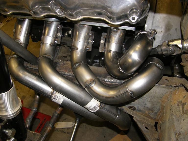
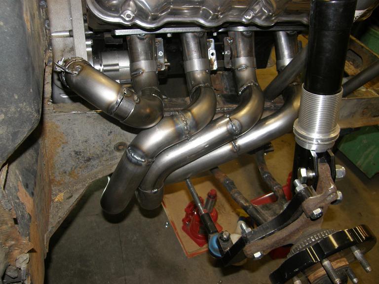
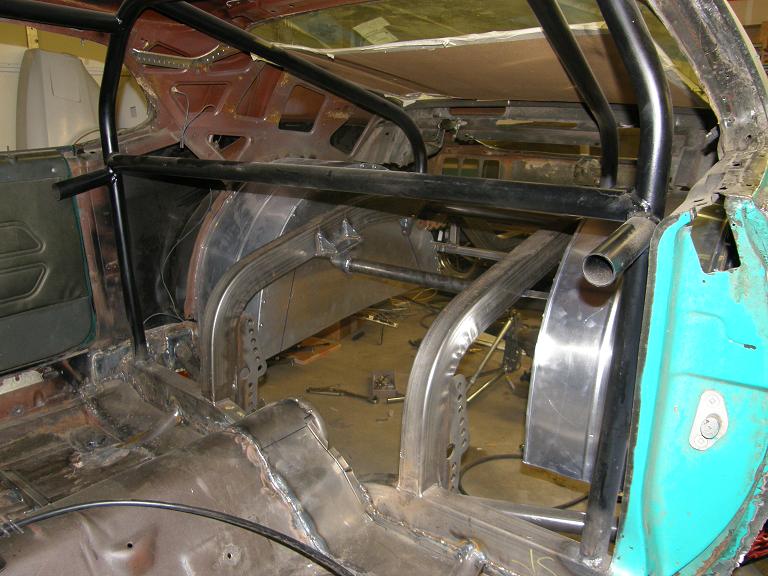
Saturday morning I had to be at work, but I got back out to the shop on Saturday afternoon for a few hours.  My plan had been to try to finish up the roll cage stuff on Saturday, such as installing the swing out side bars, welding on the tabs for the seat belts, etc.  But I just didn't feel like doing that; I was kind of pumped up to get to work on my new intake manifold.  So I decided to start on that project instead, and leave the rest of the roll cage work for later.  The first thing I had to do with the intake was to make a jig to build it on.  I had previously built a couple of sheet metal intakes, using dummy engines to get everything fixtured properly, but there were limitations to using this approach.  First of all, getting the bottom half of the runners welded up while the manifold was bolted to the engine was practically impossible, so in the past I'd welded around the top half of the runners, and then removed the manifold from the engine to weld the bottom half.  This always caused the manifold to warp, so significant other work then had to be done to get the manifold to bolt onto the engine properly and seal to the cylinder heads.  I figured I would build a jig to eliminate this problem, building the jig so that the bottom was open, and after the top half of the runners were welded, I could just flip the whole jig upside down and get at the bottom side of the runners more easily.  I'm not a particularly skilled aluminum welder, and for me access to the weld is really important if I'm going to do a decent job, so I figured a jig like this would make it a lot easier for me to build the intake.

The other advantage to the jig is that I can take advantage of my powder coating oven to pre-heat the manifold prior to welding.  This always makes aluminum welding go easier in my experience, but there is no way I'm going to horse a block and cylinder heads into the powdercoat oven for preheating.  Using a jig would make that job a lot easier.

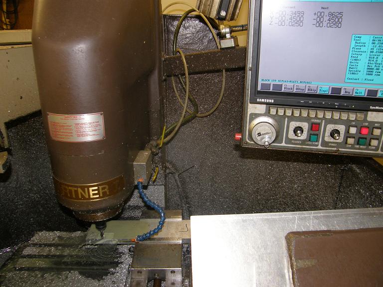
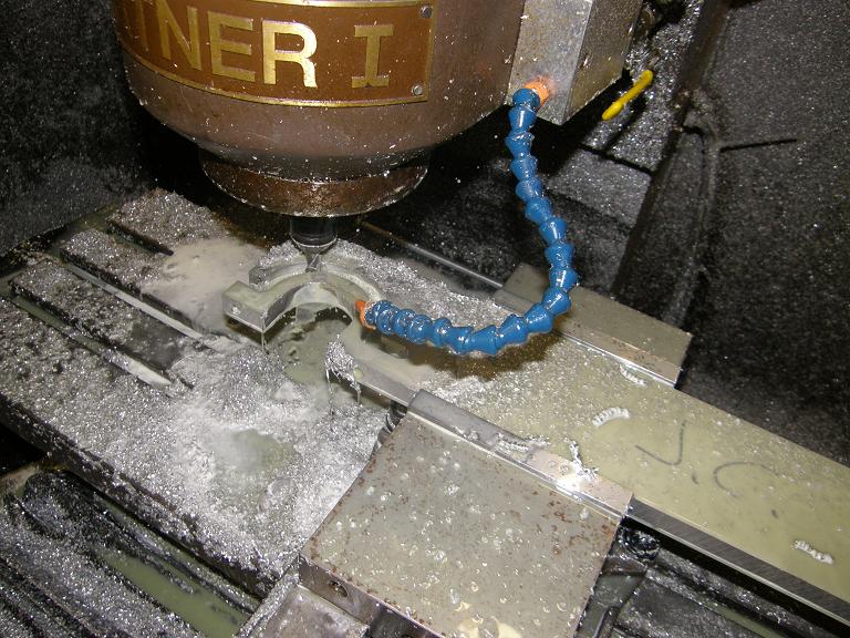
The manifold I'm building was originally conceived about two years ago, and I purchased all the materials I needed then, including the steel for the jig.  I used 1/4" wall 2X3 rectangular steel tubing to make a framework for the jig, plus some 3/8" thick angle iron to form the flanges that the intake would bolt to.  After digging these materials out, the first thing I had to do was to drill the holes in the angle iron that the manifold would bolt to.  In addition to the five holes for the manifold bolts, I also decided to add another 10 bolt holes for some 1/4" bolts that would add further support to the manifold's intake flanges, and help prevent warpage when welding.  With 15 bolt holes for each piece of angle iron, I decided to set the angle iron up on my CNC machine and drill the holes on that.  Took me about an hour to get set up and drill the holes in the first piece, and by then I had to leave the shop until later due to some family obligations.  Later that evening, I got back out to the shop and got the other piece of angle iron drilled.  Then, I had to tap all 15 holes in each piece of angle iron so that the manifold would bolt on.  My CNC machine doesn't do a good job tapping, and tends to break the tap more frequently than it actually taps the hole, so I had decided to tap all the holes by hand.  This pretty much burned up the remainder of the evening, and I was only about half way through the second piece of angle iron with the tap.

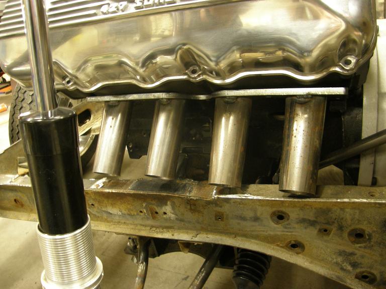
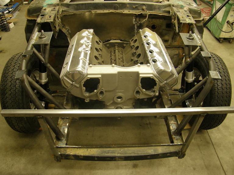
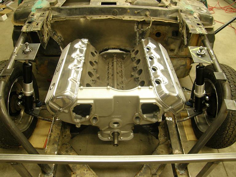
Sunday morning again I had a few hours, so I got out to the shop early, finished tapping the second piece of angle iron, and got set up to weld the jig together.  I wanted to make sure I kept it as flat as possible during the welding operation, so I cleared off my 24" granite surface plate (which I never use as a surface plate anyway), and set the four pieces of rectangular tubing up on that.  After welding them together using some caution to avoid overheating any one particular area. I grabbed one of my stock SOHC intake manifolds and bolted the angle iron pieces to that, then set up that assembly on the rectangular tube base. After I got it where I wanted, I carefully welded the angle iron to the base.  At this point the jig with the manifold installed looked like this:


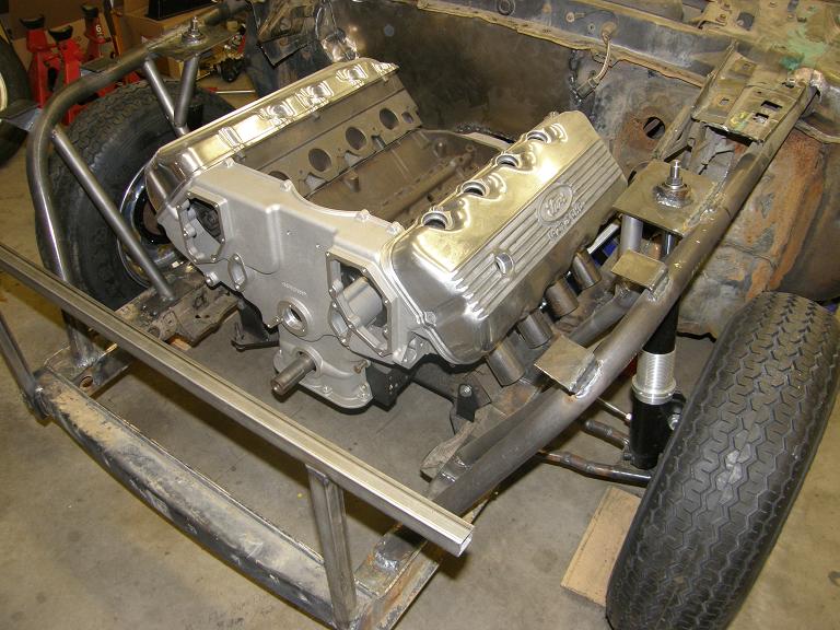
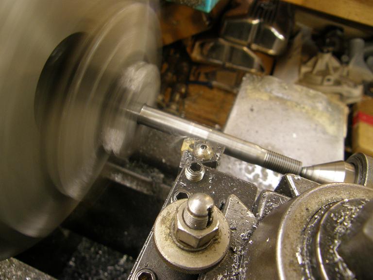
With the intake firmly fixed in place, next I used the lathe and the mill to make a piece of steel tube that welded onto the frame of the jig, to correctly position the distributor hole in the manifold.  After welding the tube in place the front of the jig looked like this:


At that point it was around 1:00, and I had more family stuff to attend to, but after dinner at 6:00 I got a couple more hours out in the shop.  The flanges for the intake manifold had already been laser cut back in 2009, before I'd acquired my CNC mill.  However, the flanges hadn't been cut for the additional 10 holes that I'd put in the angle iron part of the jig, to help hold the flange flat during welding.  Since I already had the program on my CNC for the holes I'd put in the angle iron, I just set the flanges up on the machine with the same zero point, and drilled the holes with a larger bit so that the 1/4" bolts would fit through.  Here's a pic of one of the flanges on the CNC machine:


After I got the flanges modified, I removed the factory manifold from the jig and bolted on the flanges.  Then I test fit the manifold floor in place on the jig.  Pictures below:


So, I think I've got a good start on the manifold now.  Next week I hope to get the tubes cut and welded, and the general shape of the manifold mocked up.  I'll post another update next Sunday night.


7382
Non-FE Discussion Forum / Re: Gutten tag
« on: April 01, 2011, 01:04:49 PM »
Hey Alan, nothing like an empty room, eh? :D  I haven't advertised the web site yet, so there's not a lot of people looking at it.  Hopefully when my book is ready to ship and I start pointing people to this web site to buy it, more people will sign up on the forum.  I guess we will see.  I had a new member from Germany sign up a couple of days ago; I figured this was his post!

7383
FE Technical Forum / Re: Nice Forum
« on: March 30, 2011, 07:33:35 AM »
I wonder if you couldn't get the same effect just by running a normal 3 ring package, but with small, lower tension rings.  This would probably make the whole thing more street friendly.  On my big SOHC I ran a steel top ring, .043" thick, an iron .043" second ring, and a 3mm oil ring package.  The rings were low tension, but not the lowest tension.  This setup did use some oil, but it was still usable on the street and I've racked up several thousand miles on this engine and others with this package.  Not to mention some 9 second quarter mile times in a 3900 pound car  :D

When you ran the two ring package in the brand X stuff, did you notice excessive oil consumption?  Was this a circle track application?

7384
I made more good progress on the car this week, but I'm still about a week behind where I want to be with my schedule.  This means that next weekend instead of starting my sheet metal intake, I'll need to spend at least a day finishing up getting all the body panels fitted on the car, and then probably another day making the swing out sidebars on the roll cage, adding seat belt tabs, welding on the trailer hitch, and in general finishing up the roll cage and chassis work.  I might be able to cut that time down somewhat if I can get some things done in the evenings this week; we will see.

After my last update Mario428 commented that the donut exhaust pipe that I was going to use to make a sharp bend in the #8 header tube could cause a power loss as compared to lengthening the primary pipe and using the normal radius bends.  I did a little research on this and found that there is indeed a consensus in some circles that this is true.  But I wasn't 100% convinced, and decided that this would be an interesting thing to test on the dyno.  Monday night last week I did the machine shop demo for my son's Boy Scout troop, which the kids loved but which didn't leave me any extra time to work on the car.  So Tuesday night I broke free for a couple of hours and fabricated my #8 tube out of the standard J-bends I'd been using to build the headers.  I split the #8 primary tube into two halves, with a coupler in the middle, so I could remove the new section of pipe.  Wednesday my exhaust donuts arrived from the Chassis Shop, but I was tied up with family stuff so I couldn't get back to the shop until Thursday night.  But on Thursday I managed to get the sharper, correct length primary pipe completed.  Here's a photo of the left side header with this pipe in place on number 8:


During the week I'd been talking to Steve and Jerry, trying to get a time arranged when we could all get together and thrash on the body assembly of the car.  I'd been hoping for Saturday night, because I still had the right side header to get completed, and I figured it would be easier to get that done without the front fenders on the car.  Saturday night would have left me Friday night and all day Saturday to get the right side header completed.  But scheduling conflicts intervened, and it turned out that Saturday morning through the early afternoon were the best times for Steve and Jerry.  So on Friday night I got right out to the shop and started on the right side.  Saturday morning I was back out to the shop early, by 7:30, and by the time Steve and Jerry arrived at 9:00 I was done with two of the primary tubes.  After going over what we wanted to get accomplished, we decided that I would just keep going on the right side header, and Jerry and Steve would start by getting the new doors hung on the car.

The new doors were purchased from Mustangs Unlimited, and although they were new, they were made in Taiwan or China, so we figured there might be some installation issues.  Sure enough, Steve found that the bolts weren't tapped for the right size holes for the hinges!  Seemed like they were 10mm or something, so Steve drilled and tapped them to the correct size, and then swapped the latching mechanism into the new doors so we could still close and latch them for alignment purposes.  Jerry worked on grinding some of the welds on the rear quarters where the rear fiberglass parts were to be installed, and then helped Steve hang the doors after the latches had been installed and the hinge holed redrilled and tapped.  By 11:00 they were finished with the door installation, but I was still working on the last header tube, so Jerry and Steve started on the rear end fiberglass.  Around noon my wife came home with lunch, so we took a short break to eat before getting back to work.

By 1:00 I finally had the right side header finished.  On this side I needed to run three of the four tubes outside the frame rail, otherwise there would have been no room to drop the starter with the headers on the car.  One of the tubes is a little too close to the tire when the steering wheel is at full lock, and I don't like that, but I think it will be OK; here's a photo:


At that point I pitched in to help Jerry and Steve with the back side fiberglass.  I noticed right away that the fiberglass components for this car were nowhere near as good as the ones I'd received from Crites for my Galaxie, despite the fact that these parts had been about twice as expensive.  First thing that Jerry and Steve pointed out was that the fiberglass taillight panel was warped by a good inch, and had to be bent into place in order to fit against the back of the car.  Jerry and Steve had gone ahead anyway at my direction, but after installation we noticed one spot on the panel where the stress of bending the panel had caused the gelcoat to crack.  More bodywork.

We also saw poor fit issues with the end caps that bolt onto the back of the rear fenders, and the trunk lid, which we needed to shave on the forward edge to get it to fit properly.  After screwing around with this for quite a while, we decided to leave it and get to work on the front clip, because Steve and Jerry had to leave around 2:30.  (Jerry was going to pick up his new car, a Ford Fiesta.  He was giddy about the 40 miles per gallon!  In an attempt to bring him back to reality, Steve asked how much it would tow.  Jerry was not amused.  Those guys are a riot.)

Several weeks back I had already installed the front clip on the car, and knew from that experience what a pain in the neck it was going to be.  Compounding the problem was the fact that now the inner fenders were gone, so there was nothing to bolt the front fenders to except for the tabs I'd welded on the front roll cage extension bars.  We put the fenders on anyway, and had trouble getting them to even align at the back of the fenders where they met the door.  I finally realized that I had one of the captive nuts that was supposed to go on the fender on the chassis bracket instead, and this was keeping the fenders from sliding forward to their proper position.  After we fixed that, we were able to get the fenders put on and at least aligned with the front of the doors.  Sighting down the body lines, it looked nice and straight with the body line on the doors, so at least there was hope.

Just before Jerry and Steve had to leave they helped me put the hood on the hinges, so the three major front end components were mounted.  After the guys left I took a break in the house to visit with my kids for a while, then was back out to the shop on Saturday night.  I spent the evening working on getting the rear fiberglass fit to be as good as possible.  It was a semi-hopeless task, and I can see that there will be a lot of added Duraglass to a few sections of the fiberglass, because no matter what there was no way I was going to be able to adjust the panels to fit properly.  The area right at the back of the car, where the trunk panel had to line up with the end caps, was particularly bad.  But it looked familiar somehow; I went back to my computer to look at some photos of 69 Shelbys that I'd saved off the internet, and sure enough, at least one of them had the same alignment issue!  The telltale sign of aftermarket fiberglass parts.

In any case, after doing the best that I could with the rear end fiberglass, I decided I wanted to see what the rear end of the car would look like with the taillights and bumper installed.  I had to hang the old bumper in place, which was kind of ugly, but I did have new taillight lenses and frames.  After I put them on I snapped the following photo:


I've always really liked the 68-70 Shelby taillights.  Staring at the back of the car was a pretty good motivational tool, and I went in on Saturday night feeling like I was making some progress.

Sunday morning I was back out at the shop again, this time to work on the front end.  I could see that the front left fender needed some more alignment work back at the door, so I took it off and replaced it a few times, trying to work it into the correct position.  Finally I realized that the problem was the door, not the fender.  The door gap along the rocker panel was 3/8" at the back of the door, and about zero at the front of the door.  I loosened the hinges and pried to door up to even the gap.  Next fit of the front left fender looked much better, and after a few more tries loosening and tightening the mounting bolts while adjusting the fender I finally had an acceptable fit.

I spent the rest of the morning and part of the afternoon on Sunday getting the front end of the car more put together.  Most of this work focused on the headlight buckets, which were a huge pain in the butt to get fitted with the hardware for the headlights, and bolted correctly into the front fenders so that they fit properly and were aligned with the fenders.  I also worked on installing the fender bolts into the tabs I'd welded onto the roll cage extension bars, and repositioned the front crossbar of the radiator mount a little to line up with the fenders better.  I had to call it a day at 3:00 PM because I had other commitments, but I was finished with the front end work up to the front bumper.  Here's a couple of photos of the car as it is now:


Despite this progress, I still have a good eight hours of work to do on the front end fiberglass.  I need to build brackets for the bumper, plus add the small fiberglass panel underneath, and then add tabs to mount the grille and front marker lights.  I also have to add brackets for the hood pins, and cut the hood for the hood pin installation.  Hopefully I can get this done during my free evenings this week, so that I can spend a day next weekend on the rest of the roll cage work, and then start the sheet metal intake next Sunday.  We will see what happens; I'll post another update next weekend.

7385
FE Technical Forum / Re: Nice Forum
« on: March 26, 2011, 03:16:35 PM »
Welcome Bill, and I'm glad you like the forum.  Unfortunately I have zero experience with running a two ring piston, so I can't really offer you any advice.  I sure would be interested in hearing how it works out though; good luck with the project!  Jay

7386
FE Technical Forum / Re: Timing, Heat and A/F ratio?
« on: March 26, 2011, 03:15:02 PM »
Heat; I've noticed that with less initial timing, idle heat is higher.  On my 445, 10 degrees is hotter than 12. (195 @ 10, 180 @ 12) in addition I can get a smoother idle at 10.  Is 12 to much?

Air Fuel ratio;  Is there a relation ship between optimum timing, carb tuning and the resulting A/F ratio?  If I've tuned my carbs for the best idle and A/F, will adjusting the timing have an affect on the A/F and how much.


Twelve degrees of initial is not too much in my opinion, and I've run as much as 20 myself.  More timing will generally make the engine run a little cooler, at least to a point, so that is no surprise.

I think your A/F will be affected by timing, since the timing will affect when and how completely the mixture burns.  There is an optimum timing point for any engine, and once you think you've got it dialed in, that's when you should be jetting to get the proper A/F.  Small changes in timing probably won't have a noticeable effect on A/F, though, so if you are talking about going from 10 to 12, I doubt you'll see much of a difference.

Hope that helps - Jay

PS - spellchecker is now enabled!

7387
FE Technical Forum / Re: My experiment "The Tractor Motor"
« on: March 21, 2011, 11:53:07 PM »
I'll be curious to see how this works out, and wish you the best of luck with it.  One of the issues to watch for is a crack developing between one bore and the next at the thinnest point between them; cutting the material out for the sleeve can weaken this area to the point where it can't stand the stresses there anymore, and this crack can develop after some heat cycles.  I've seen this happen when two consecutive cylinders are sleeved for a repair, and then the heads have to come off and the crack has to be pinned to repair it.  I even had one guy tell me that he pins the middle of the deck between the sleeves even if there is no crack present.  Seems to me Wes had this problem too, although I can't remember for sure.

I have also been told that you can get away with sleeving two consecutive cylinders if you use the thinner .090" wall sleeves, and don't make them a real tight press fit in the block.  Using that logic, you should be able to sleeve all 8 holes using this technique.

In any case, I've never done something like what you are doing here, so what do I know.  If this works out, it will be a great way to create a 427!  Good luck with the project; I am looking forward to your updates - Jay

7388
Thanks for the comments, Mario.  So, you are saying that by using the very tight radius of the donut bends that this will restrict the exhaust, and have a more negative effect on the power output than one extra long primary tube?  I guess I hadn't really thought of that as an issue; radius of the donut tube bend is about 1 1/2", and radius of the normal J-bends I'm using is 3", and I figured as long as the pipe was smooth I'd be OK either way.  Where would I find more information on this?

By the way, I use Pipemax when calculating lengths for headers and intake manifolds, but based on the dyno testing using my Hilborn setup it doesn't translate perfectly in the real world.  Pipemax predicted a 17" runner length would be optimal for my Hilborn setup on the big SOHC at 7000 RPM, and 20" turned out to be what the engine wanted.  It also gives conflicting results on exhaust system lengths; for example, on this set of headers, Pipemax says that the OD of the first primary tube should be 2.275", but that for optimum exhaust gas flow the pipe should be 2.1".   So, my opinion of Pipemax is that its a good tool that will get you in the ballpark, but it is no substitute for empirical testing.  You probably knew that  :D

7389
This week was header week, and I had hopes at the beginning of the week of getting the headers completed by today.  Unfortunately real life intervened again, with my attention being required on several other projects, including my book.  I haven't talked about the book much in this blog, but in a nutshell after sending it off for printing at the beginning of January, I got my 1000 copies back on January 31.  The pictures in the book did NOT look good, and there were some obvious printing defects, like lines through the photos and variations in the darkness of the print.  I complained immediately, but it took a solid 6 weeks to finally get some action out of the printing company.  They agreed to reprint the book at no cost, but suggested that the printing method that I used and the paper that I had selected were not ideal for good quality black and white photos.  They suggested a different type of press and paper (more money, of course), but I agreed because I didn't want to go through this whole mess again, in case the press and paper really were limiting factors.  This week they sent me another proof, so I had to spend a couple of days reviewing that.  I decided at the same time that I wanted to change the contrast and brightness in some of the photos to improve the look of the proof, so I spent Wednesday and Thursday night revamping about 30 photos.  Friday I sent off the revised file, and will probably get another proof at the end of next week.  Then, hopefully, the book will finally get printed correctly.

Saturday I had a couple of machining projects to finish up, which I thought would only take a couple hours but ended up taking all day.  One of them was preparation for my son's Boy Scout meeting on Monday night; the troop is coming over to my shop to see a demonstration of what machine tools are and how they work.  I wanted to be prepared to have the Scouts machine something that they could take home, and it took me longer to set that up than I originally anticipated.  But at least Monday night should go well.

Sunday I finally got back to working on the car.  I started with the driver's side header, and had a bunch of mandrel bent J-bends on hand to make the pipes.  I'm using a stepped header design with 2 1/8" to 2 1/4" to 2 3/8" pipes, plus a slip on collector.  I stared at the car for a while to try to visualize where everything was going to go, and then started on the first pipe.  I've probably built 15 sets of headers in my life, and after coming up with a basic strategy for each side I've found that the best thing to do is dive in and start cutting and fitting.

Cutting to the chase, eight hours later I had the driver's side done, with the exception of the 2 1/8" pipe from cylinder #8 to the 2 1/4" pipe coming up from the collector.  I could have done that one, but I was trying to maintain equal length and this tube would have been a good 6" longer than the rest if I'd built it with the pipes on hand.  I figured out that if I bought some of those exhaust pipe donuts from the Chassis shop I could cut at least 5" out of the first 2 1/8" pipe, bringing it into line with the rest of the pipes for length.  So, I've left that pipe for now, and will order the donuts tomorrow.

Here's a couple of photos of the left side header; you can see the missing primary on #8, and in the background the 2 1/4" pipe that it needs to meet up to coming up from the collector, in the first picture:


I'm sure I can get the left side header finished up and the right side header done next week, but I'd really like to get them done before 4:00 or so on Saturday, because Steve and Jerry are coming over again next Saturday night.  We're going to get the new doors hung on the car, and hopefully get the front clip on and adjusted, plus the rear taillight panel, trunk lid, and end caps on and adjusted.  With that done, and the headers finished, I'm on to the next project, which will be a sheet metal intake manifold for the car.  I've given myself most of April in my schedule to get the sheet metal intake built, installed, and then dyno the engine.  May is going to be bodywork and paint month, and June will be assembly.  Maybe on the road by July...


7390
FE Technical Forum / Test Photo
« on: March 18, 2011, 09:40:59 PM »
These photos are hosted by Photobucket, as described in the Forum Information and Rules post:


7391
I made some solid progress on the Shelby clone again this week, despite limited time over the weekend. During the week I had been able to get the driveshaft loop mounted and the rear sway bar brackets tacked into place, so on Friday night I pulled the differential out from under the car, and started getting the sway bar brackets and watts linkage brackets on the chassis reinforced and finish welded. I had to cut some reinforcing tabs out of 1/8" steel plate to strengthen the driver's side watt's link bracket, which extended down from the frame quite a long ways. I also used a tab to reinforce the passenger side bracket, and several triangular pieces to reinforce the sway bar mounts. By around midnight on Friday I finally had the welding done under the car, and went in for the night, ready to tackle the next project.

Saturday I was tied up with family activities, but Sunday was a free day, so I got out to the shop early on Sunday morning to get to work. I had decided to work on the wheel tubs next. I wanted to get this done because I needed a few more tabs under the car to support the wheel tubs, and with them completed I could install them and mount the tabs, and that would essentially finish the chassis work under the rear of the car.

If I recall correctly I purchased the wheel tub kits from Summit Racing, several years ago when I purchased the car originally. The wheel tubs were designed for a maximum size tire diameter and width, but since I was using the factory outer wheelhouse on the car, I needed to revamp the wheel tubs to make them fit. From a cross section standpoint they needed to match up with the shape of the factory outer wheelhouses, and from a width standpoint they didn't need to be the full width from the outer fender to the inner frame rails. In fact, I wanted to keep them 3" outboard of the frame rails, because this would allow me to run fuel and brake lines outside the frame rails, without going into the wheel tub. So, I envisioned some 3" brackets, welded to the outside of the frame rails on each side, that the wheel tubs would be attached to.

The wheel tubs come as two pieces that fit together with kind of a tongue and groove arrangement, as shown in the photo below:


My first thought was to cut the half moon shaped piece of the wheel tub to match the contour of the factory wheelhouse, and then bend the side over so it would look like the original piece, and slide it into the groove in the flat part of the wheel tub. Here's a photo of the two wheel tub pieces, with one of the contours marked on the half moon shaped piece:


Unfortunately, this didn't work out because I couldn't easily get the side of the half moon piece bent over in a smooth curve. As soon as I got to a point where the curve wasn't smooth, the bent part didn't want to slide into the groove in the flat part. After several attempts at rebending, with limited success, I decided to go to a different approach. I bent the grooved portion of the flat part out at a 90 degree angle, and used pop rivets to put the two pieces together. Here's a couple of photos showing this process:


Back underneath the car I positioned the wheel tubs and used Klecos to hold them into position. After I had them where I wanted them, I cut up some 1" wide section of 2X3 rectangular tubing, and then cut these diagonally so that I had two 1" wide L-shaped brackets. I positioned these brackets so that they extended from the 2X3 rectangular tube frame, and the smaller leg of the L butted up against the wheel tubs, and tacked them into position with the wire feed. After I finished tacking I welded all the brackets into position, and drilled holes for Klecos to secure the inboard side of the tubs. Here's a couple of photos of the wheel tubs in position, from under and inside the car:


The wheel tub project had burned the whole morning and most of the afternoon, so I only had a couple hours left in the shop that I could get something accomplished. I decided to spend the time I had left finish welding on the axle housing. All the required brackets had been tacked in place, so they just had to be finish welded. Also, the axle housing ends and the back brace had to be finish welded to the housing. I've always been concerned about warping the axle housing during this operation, so I go very slowly, welding beads around 3/4" long on several spots that are widely separated on the axle housing, and letting the housing cool for a few minutes, before doing this again. After a couple of hours of this I had about half the welding completed; here's a photo of the axle housing:


I should be able to finish up this welding in the evenings this week. Next project is the headers. I got all the tubes for building the headers this week, so I should be able to make a big dent in that project next weekend. Also, my friends Steve and Jerry will be coming by either next weekend or the weekend after, for a "barn night" to help me get the new doors and all the Shelby fiberglass hung and fitted on the car. After the headers and the body panels, it will be time to start my sheet metal intake, probably around the beginning of April. I'm looking forward to building that, and seeing how it performs on the dyno! I'll post another update next Sunday night.


7392
This week I cleaned up a lot of small projects on the car, and by late in the day Sunday the car was looking more complete than ever. My driveshaft had arrived from Mark Williams this week, but before I put it in and started on the rear end work, I wanted to finish up in the interior. Wednesday night I got a few hours in the shop and was able to get the plates welded to the floor for the seat mounts, and also spent a few minutes getting the shifter mounted to the floor. On Friday night I installed the Lokar gas pedal, and then unbolted the Wilwood brake pedal assembly and the steering column from the cross bar and pulled the bar out of the car, so that I could finish welding and reinforcing the brake pedal mount.

On Saturday morning I had a few more hours out in the shop, and worked on the the welding and reinforcements for the cross bar. After finishing with that I made up a cardboard template for the hole I needed to cut in the firewall so that the master cylinders could bolt to the Wilwood brake pedal assembly. Then I repositioned the cross bar between the two front roll cage uprights, bolted the brake pedal mount to the hole in the firewall to make sure it was aligned correctly, and welded the dash bar into position.

Next I bolted the master cylinders on the brake pedal assembly, and tried to fit the assembly into position under the dash. Unfortunately the master cylinders wouldn't quite fit through the hole in the firewall, so I had to do some additional trimming to the firewall. This was a contortionists nightmare; I couldn't easily get at the hole from the engine side or under the dash side to trim it, but finally using a small cutoff wheel on a die grinder I was able to trim the opening where it was needed. Finally I got the pedal assembly and the master cylinders mounted, and took off the tape from the master cylinders where the reservoirs were mounted , and installed the reservoirs. The photo below shows the master cylinders; there is a pretty nice clear area between the master cylinders and the back of the engine:


My alternative to this setup would have been to retain the stock pedal and use some kind of a double pivot linkage arrangement to relocate the master cylinder up and out to clear the engine. I thought that this would be a lot of work, hence my selection of the Wilwood pedal and master cylinder assembly, but as it turned out getting the Wilwood pedal installed was a lot of work too. Hindsight being 20/20, I think I would have given more thought to the double pivot linkage scheme before settling on the Wilwood pedal, but one thing for sure is that if I had gone that route, I might still have limited access to the back left side of the engine with the valve cover off, and of course with the Wilwood master cylinders being completely behind the engine, that is not an issue with this setup.

The last thing I did on Saturday before heading out to watch my daughter's basketball tournament was to put the seat tracks on the passenger side seat, and bolt the seats and the shifter into the car. With both pedals, both seats, the steering wheel and the shifter installed, it was starting to look like a real car! Of course, it all has to come apart again for cleaning and painting before final assembly, but having the interior essentially all put together except for the dash (which I plan to custom fabricate later) gave a good sense of progress.

I had another basketball game to attend on Sunday afternoon, so I set my alarm for 7:30 and was out in the shop with a hot cup of coffee by 8:00. I was looking forward to getting to work on the rear end. After cleaning up under the car so I had a clear area to work, I positioned three floor jacks under the rear end to allow precise positioning, including in the rotational axis, and jacked up the rear end so that the tires were where I wanted them in the wheelwells. Next I unboxed the Mark Williams driveshaft and installed it; it fit perfectly. Finally I checked the angles of the yoke coming out of the Gear Vendors unit and the rear end yoke, and pumped up the center floor jack until the angles were the same. Back out from under the car, I pushed the rear end back and forth a couple times until the tires were spaced the same distance from the wheelwells, and now I finally had the rear end aligned properly under the car. I made sure that the ladder bar brackets were square on the axle housing, and tacked them into place in several spots. Here's a couple of photos of the car at this point:


Next I decided to tackle the rear coil over shock installation. I've had the shocks for this car since I purchased the S&W back half kit in 2005, so it took me a while to find all the brackets that came with them, and figure out how they were supposed to weld to the rear end. After I got this figured out it became clear that I needed to get the back brace tacked in place on the axle housing before I could weld on the lower shock mounts. I trimmed the four link brackets in back of the axle housing to allow the back brace to be installed, then tacked it into place. Then I modified the lower shock mount brackets to fit in place over the back brace, and assembled the shocks and brackets, hanging them in place from the top shock mounts that had been welded into the back half kit at S&W. Making sure they were aligned vertically, I tacked the lower shock mounts in position. Photo below:


After the shocks were installed I started looking at installing the rear end locating device. The S&W kit had come with a panhard rod, but I had purchased a Watts linkage kit from Speedway to try to get better location than the panhard rod could provide. The Watts linkage had come with bars that were about 20" long. With a panhard rod, the longer the rod, the better the suspension geometry. I knew that the same would be the case with a Watts linkage setup, but really didn't know how narrow I could make the mounting points. The width of my back half frame rails was only 24", so I was going to have to cut the bars down in length to about 12" in order to fit the frame rails. I decided to do a quick CAD drawing to confirm that shortening up the bars would still allow me the suspension travel I needed. I figured I needed 3" of up travel and 5" of down travel from the static position of the rear suspension to make sure there was no binding during normal suspension operation. The drawing below is the CAD drawing I made up to check this:


The drawing showed that in the range of suspension travel of interest, there was no issue with binding, and the Watts link should locate the rear end side to side effectively. I cut the bars down to the length I needed, which turned out to be 10 1/2", and then rethreaded the cut ends for the rod ends that needed to screw in there.

I was about ready to head off to the basketball game, but before I did, I laid out the Watts linkage and the other rear suspension piece that needed to be installed, the rear sway bar, shown in the photo below:


Unfortunately (or fortunately, depending on your perspective), my daughter's basketball game was a bust; the other team failed to show. So, we were back at home by 3:15, giving me a couple more hours to work on the car before I had to call it a day. After a bunch of measuring, cutting, fitting, and trial welding and re-welding, I finally got the Watts linkage installed with the bars parallel; photo below:


The rear sway bar doesn't look like its going to be a big deal to get installed, so I think I can probably get that done during the week this week. Then the rear suspension has to be disassembled and all the suspension brackets have to be finish welded to the axle housing and the frame. I also need to get the aluminum wheel tubs installed once the axle housing and tires and wheels are out of the way. Next weekend I won't have a lot of time to work on the car, but hopefully I can at least get those things taken care of. After that I can start the headers and the aluminum oil pan that will be required for the car, and finally get all the body panels on the car, essentially completing the chassis work. It looks like I should be able to get this done by the end of March (crossing my fingers ;-))


7393
Once again I made a lot of progress on the car this weekend, but once again I also fell a little short of my goals for the week. I did make it out to the shop on a couple of weekday evenings this week, and made some progress on the work under the car. The first thing I did was bend up a subframe connector out of roll cage tubing for the driver's side. After a couple of hours bending, fitting, and notching, I had the tube shown in the photo below:


The small tube coming off perpendicular to the long one was welded on after the photo was taken and also connects into the front subframe, to give some leverage to the bar. I planned to attach the bars to the front subframe by first welding some 1/8" plate to the side of the front subframe rail, and then welding the tube onto the plate, to spread the load. At the back the bar would tie directly into the 2X3 crossmember of the back half kit.

The next free night I worked on the transmission mount. I was getting tired of working around the floor jack that was holding the back of the transmission and the GVOD up, so rather than work on the passenger side subframe I spent some time figuring out how to make the trans mount work. I wanted to use the factory support welded into the unit body of the car that was used with the stock transmission mount, and it seemed like the best way to do this was to build a new mount out of 1" square steel tubing. The back half of the mount was pretty easy, just a straight piece of tubing with a little angle up on one end, but the front half had to dip down to clear the trans brake solenoid, complicating the design. Eventually I got it pieced together, with the back and front tubes welded together with a plate that I slotted some holes in on my mill, to allow some flexibility in position of the transmission. A photo of the partially completed mount is shown below:


After some more welding and some grinding, the mount was ready to install. It seemed to fit fine, and allowed me to pull the floor jack out for better access.

Saturday morning I got back onto the project by bending up the passenger side subframe connector, and spent the rest of the day grinding, fitting, and welding until the subframe connectors were installed. I also notched the original factory support for the transmission mount to allow the header collectors to sneak through this area, improving the ground clearance situation. Here's a photo under the car, showing the front half of the subframe installation and the trans mount and notch in the trans mount support:


At the end of the day Saturday, after finishing all this stuff, I started thinking about what to do next. One of the bigger challenges left was to get the Wilwood brake pedal and master cylinders mounted, so I spent some time planning out how I would proceed on that in the morning. The Wilwood brake pedal mounts two separate master cylinders that extend into the engine compartment, but they are shorter than the stock master cylinder, so they wouldn't interfere with the big SOHC engine. The master cylinders mount to the firewall facing bracket of the pedal, but the pedal bracket itself is supposed to mount from the top, to some kind of a frame member.

When I had replaced the section of the firewall with a flat steel sheet, I had automatically been put under an NHRA rule which says that if you remove more than one square foot of the firewall, you have to run a crossbar between the front uprights for support. This crossbar can be 1.25" diameter .058" wall chrome moly, so I had ordered some of that tubing earlier from S&W race cars. I decided that I would use the crossbar as a forward support bracket to mount the pedal assembly. I figured I could run some square steel tubing between the crossbar and firewall, and mount the pedal assembly from that.

Sunday morning I was out to the shop by 9:00, hoping to make some good progress before noon, when I had some family commitments. I opened the door to the shop and the first thing I noticed was a whiff of propane in the air. Ruh-roh. I walked out of the shop without turning anything on, and went out and looked at the gauge on the propane tank. It was almost completely empty, showing only about 3% on the gauge. This explained the smell; when the level in the tank goes down that far the pressure in the lines drop, and one of my heaters has a hard time lighting. It will flip on and try to light for 20 seconds or so, then automatically shuts off to prevent a major leak of propane into the building. While it is trying to light, propane is coming out of the gas line, resulting in the smell. It will repeat this process every 15 minutes or so, and results in a faint propane odor in the shop.

I shut the valve off on the tank, carefully opened one of the overhead doors in the shop to air it out, and considered the necessity of working in the shop with no heat. I didn't want to just keep the other heaters on until the propane ran out, because the gas company needs to do a leak check on the building if the tank is completely empty. I decided that despite the lack of heat, I could tolerate working in it for a while, so I started back in on the car by 9:30. The thermometer in the shop read about 38 degrees, which wasn't too bad.

First thing I had to do was remove the factory brake pedal and pedal tree. Of course, this piece also functions to hold the steering column in position, so before removing the tree I had to fabricate an X-shaped wood support to hold the steering column in position. Later I planned to machine a U-shaped bracket to bolt to the crossbar, which would position the steering column. After the wood support was installed, I removed the factory brake pedal and pedal tree.

I cut the 1.25" diameter chrome moly crossbar carefully and notched the ends a little at a time, so that when it was finished I had a nice snug fit between the front cage uprights. Next I figured out where I wanted the pedal, and mounted it without the master cylinders, but using the master cylinder bolt holes so I could position it where I wanted against the firewall, and temporarily bolt it into position through the firewall. Then I made up a mounting frame that the top of the pedal assembly would go to, from 1" square steel tubing, that would weld to the crossmember and extend to the firewall, where it would bolt in place through a support plate I would weld to the outside of the firewall. By noon I had the basic arrangement frame up, as shown in the photo below:


Later in the afternoon after returning from my family commitment, I decided that I'd better get to work on the U-shaped bracket that would hold the steering column to the crossbar. I decided to make this on my CNC machine, because it would be faster than doing it manually on the Bridgeport. I drew up a rudimentary sketch of what I wanted on my whiteboard, selected a piece of 3/4" thick aluminum plate that I had in my materials pile, and spent about a half hour programming the machine to make the part. Once it started up I was able to keep working on some other projects while the part was being made. Here's a couple of pictures of the CNC machine working on the part:


One of the things I did while the machine was running was to decide how I would bolt the U-bracket to the cross bar. I decided to take the low tech route on this, and cut a piece of 1 1/2" angle iron, with holes drilled in it at the proper locations to take the bolts from the U-bracket. The angle iron would just weld to the crossbar, and the bracket would bolt to that. Here's a photo of the finished aluminum U-bracket and the angle iron piece:


Before going in the house tonight to help the kids with their homework for Monday, I bolted the bracket to the piece of angle iron, and positioned it up against the crossbar. After double checking the steering column position to make sure it was correct, I tack welded the angle iron bracket to the crossbar. Finally, I removed the wood support on the steering column, and snapped the following photo:


I still haven't welded in the crossbar yet, so now that everything is tacked in place I will remove the brake pedal assembly, disconnect the U-bracket, and pull the crossbar out of the car, where I can finish welding everything solidly in place, and add some support gussets and brackets to the brake pedal mount. Then, I can reinstall the crossbar and weld it in after it is positioned correctly.

I was hoping to get the Lokar gas pedal installed today, along with the supports for the seats so that I could bolt them into position, but I ran out of time for that. Besides, it was getting cold out there! I will have to call the propane company for a fill tomorrow. With luck I can get the gas pedal and seat supports done during the week this week, and my driveshaft will hopefully arrive from Mark Williams, so that I can finally tackle the rear end welding next weekend, in addition to finishing up the front crossbar and brake pedal / master cylinder installation. Then, the week after I can start the headers, and the chassis work will be getting close to completion. I will post another report next weekend.


7394
This week was another fairly productive week on the new car, although I didn't get done as much as I wanted to. I had been planning to get the driveshaft angles set and get the rear end components mounted and tacked into place this weekend, but on Monday when I ordered the driveshaft I decided that I'd rather have the driveshaft on hand and installed before I finalized the rear end configuration. So, instead I decided to move ahead with finishing up the chassis work at the front of the car, and then look at getting some tubing installed to tie the subframes together.

It turned out that the work on the front of the car took longer than I thought. One of the things I wanted to do at the front was to drop a tube down from the front roll cage extension tube to the factory frame rail, in order to support the frame where the front suspension load would be. As I was looking at this on Friday night, it became clear that the header pipes had to come straight through this area, and if I didn't put the tube in the correct spot it would interfere with the headers. So, before I could even start thinking about positioning the tube I had to know where the header pipes would be.

As a result, I spent Friday night and early Saturday morning fabbing up the first several inches of primary pipes and the header flange for each side. I was hoping to have at least six inches of straight pipe coming out of the head ports before turning the pipes towards the back of the car, but it appeared that this might be optimistic, based on the location of the exhaust ports and the stock frame rail. No way to tell for sure without actually mocking it up, though. On the heads I'm using the ports exit the casting at a 15 degree angle, so the pipes have to be welded onto the header flanges at this angle to keep the exhaust coming out of the port in a straight line. I dug out some 2 1/8" exhaust pipe for this task, because I was planning on using 2 1/8" to 2 1/4" to 2 3/8" stepped headers, just like what I had previously used for my Galaxie. This would allow me to re-use the collectors from those headers; since this car is getting the 585" SOHC from the Galaxie, I'm going to put my 510" engine back in the Gal, and I have a different set of headers for that engine.

On the topic of the Galaxie, I got an interesting call from my friend Joel this week (aka Captain Stabbin', also aka the Trunk Monkey). Joel suggested that I get the Galaxie ready for Drag Week in 2011 also. He offered to donate an 800 HP capable manual transmission and clutch setup so that the Galaxie would be a stick car, and he could drive the Galaxie this year, while I drove the Shelby clone. That's a pretty interesting idea that I'm still considering; it would be fun to have two cammer cars at Drag Week! Of course, I have a perfectly good C-4 and driveline for the Galaxie, and the car was already set up for that, so I wondered why Joel wanted to swap in the manual. He responded that he really didn't want to drive a car with "that oily, greasy, smelly fluid coupling behind the engine" LOL! But I'm not sure I'd want to run somebody else's transmission in the car, to say nothing of having two cars in the same class, and the extra expense of fielding two cars at Drag Week. I'm still thinking about this; no decision is required right away, and we will see how things play out this year. But it sure would be fun to have both cars at the event.

Back at the header flanges, I cut some 6" sections of the 2 1/8" tubing, cut off at a 15 degree angle, and welded the tubes into my header flanges. After getting done with this on Saturday morning, I installed one of the flanges on the driver's side to see how it would fit. Unfortunately, as I had expected, the six inch head pipes were not going to fit; at the back the flange wouldn't even bolt into place on the engine. Here's a photo:


It looked like if I cut the pipes down to 5" the flange might at least bolt onto the engine, and give me an idea of where the pipes came past the frame rail. Also from this mock up it appeared that the spot weld flange at the edge of the frame rail was going to be in the way of the primary pipes. As result I decided to cut this flange off the frame rail, and weld up the seam. After getting this done I cut an inch off all the driver's side primary pipes and was able to get the header flange mounted on the engine.


Sorry for the poor photo quality. With the pipes on the engine, I was able to determine where I had to put frame tube so that it would not interfere with the header pipes. I also took a mandrel bent section of 2 1/8" exhaust pipe and using this as a gauge, determined where I would have to cut the primary pipes off in order to get them past the frame rails. It looked like the straight section of pipe would be anywhere from 3 1/2" to 4" depending on the pipe's location. Not as long as I was hoping, but at least livable, and certainly a lot longer than the pipes would have been had I opted to go with a Boss 429 style engine compartment.

Shortly after this a couple friends of mine stopped over to ask some SOHC questions; one of them is in the business, and has a customer who would like to put an SOHC in a Cobra replica, so he wanted to take some measurements off one of the engines I have on an engine stand to see what kind of fitment issues he would be dealing with. While talking we were looking at the front end of my Shelby clone, and they suggested that I use some of the 1 1/4" chrome moly tubing I had on hand to triangulate the front roll cage extension. They suggested going from the junction welded at the front of the stock frame rail, up to the upper strut mount, and then back down to the stock frame rail at the firewall. I could still run my bar from the middle of the front roll cage extension down to the stock frame rail to support the suspension mounting point and engine mount area, but the other bars would triangulate the whole setup.

I really liked this idea. After my friends left I started working on this, but quickly came to the realization that this triangulation bar would cause a couple problems. One would be that it would limit my ability to remove the engine's valve covers, especially if I used studs to mount them. The second, and more serious issue was that by putting in a bar that ran down to the stock frame rail at the firewall, I would seriously limit the room for the headers to go through this area. The room on the driver's side was already limited by the steering linkage, and I figured I could only fit a couple of the header tubes through there as it was. Installing the bar meant that at least three of the tubes, and maybe all four, would have to wrap underneath the stock frame rail. This would lead to ground clearance issues that I didn't want to contend with, so after kicking it around a little I went back to my original plan, which was the bar down to the stock frame rail, a short support bar up to the upper strut mount, and a triangulation bar at the front of the roll cage extension tube, similar to what I'd seen on certain aftermarket roll cage kits.

By the end of the night Saturday I had the bars cut and tacked in on the driver's side. Sunday I spent most of the day on the equivalent passenger side tasks. Here's a couple of photos of the front of the car with these modifications:


I also got my new front wheels this week, and had the front tires mounted; Sunday afternoon I swapped them onto the car. Here's a photo:


I think those wheels look pretty good. I was really waffling between these Centerlines and Weld Wheels, and I liked the Weld's because they look good too and are probably a little lighter. However, the Welds were double the price of the Centerlines, and they are also not available in a 5 inch or 6 inch width. I didn't want to go with a really narrow rim in the front, because I don't like the way the cars handle with the 3 1/2" wide wheels, plus I've had some bad experiences with road hazards and the narrow wheels (pothole + 3 1/2" wheel = blown tire and bent rim). I've also seen this at Drag Week, in 2005 when one of the guys in my class hit a pothole and blew a tire. So I settled on the Centerlines because they were available in a 5" rim width.

Next I spent some time trial-installing the front seat in the interior, because I wanted to determine how I was going to mount it. I was thinking about installing the subframe connection bars so that they came through the floor behind the front seats, but I didn't want to do this without knowing first where the seats would be installed, in case there was some interference there. After I got the driver's side seat installed, I finally got a chance to sit in my new car. The seating position was good, and mounting the seat farther back from stock gave me plenty of leg room, which is sometimes a problem in early Mustangs. Here's a picture of the admittedly incomplete interior:


Finally, the last hour out in the shop today I spent the time laying under the car, and figuring out where I was going to run the tubes to connect the subframes, and also how I was going to make up the transmission mount. Based on the seat position I figured I'd be better off running the tubes completely under the car until I got right up to the rear subframe, and then just notch the floor a little and bend the pipe to come through and weld to the back half crossmember. I also figured out that I could notch the factory unit body crossmember that the transmission mount attaches to so that the header collector could come through up near the floor of the car, for maximum ground clearance, and then reinforce the notch to maintain the required strength for the mount.

At the beginning of the week I had been hoping that I would be able to get the subframe connections and transmission mount completed this weekend, in addition to the front end work, but obviously this will have to wait for next weekend. It is pretty obvious at this point that there is no way I'll be done with the chassis work by the end of this month as I was originally hoping, and with certain family commitments in March, it is probably realistic to assume that the chassis work won't be completed until the end of March. Hopefully this will still leave me enough time to get the car painted by mid-May, and on the road by the beginning of July. We will see...


7395
This week was a fairly productive one on the new car project. Last week I had gotten stalled on finishing up the steering installation due to different thread size on the manual rack as compared to the power rack, and the requirement to make a rack extension incorporating these threads. On Wednesday I received the tap and die for the 16mm X 1.0mm thread size I'd ordered from McMaster Carr, and also the 4130 chrome moly steel to make the extension. Wednesday night I snuck out to the shop rather late and got the 16mm bar threaded up about an inch, which was going to be needed for the extension. Thursday night I had a little free time after the kids went to bed, so I thought I would drill the 1 1/4" bar with the 15mm drill bit I had purchased. Unfortunately I ran into a problem with this, because the drill bit wasn't necked down at all to fit into the chuck, and the chuck for the tailstock of my lathe would only go up to 1/2" (about 12.7mm).

I thought about drilling the hole 9/16" and then boring it the rest of the way to 15mm (0.590"), but my small boring bar isnt' that stable, and I had to bore the hole a long way, so I didn't feel that this was a reasonable option. The best option would be to purchase a new chuck for the tailstock that would hold a larger drill bit. Buying new tools is always a double edged sword for me; on one hand, I hated the idea of spending a bunch of money on a new chuck just to drill one hole, but on the other hand, as a confirmed tool junkie, I love getting new tools!

I decided to go ahead and buy a new chuck. I went through the Enco web site and found a cheap chuck with a capacity of 1/8" through 3/4", and also the adapter required to fit the #4 Jacob's taper hole in the back of the chuck and the #3 Morse taper of my lathe's tailstock. Friday morning I called Enco and paid the usual exorbitant fee to get the parts shipped and delivered to me on Saturday; I was really keen on getting the rack extension made and the steering system finished up over the weekend.

Saturday morning my wife and kids were off at a basketball game, so I had some free time in the shop. The new chuck and adapter had not arrived yet, so I decided to tackle a project that I had been putting off. Part of the firewall of a '69 Mustang extends out into the engine compartment farther than the rest of the firewall, and I wanted to cut this piece out and replace it with a flat piece of sheet metal to give me more room behind the engine. I hate sheet metal work, so I decided to tackle this project right away while I was fresh, and hopefully get it finished up fairly quickly. After crawling into the engine compartment and using some straightedges to determine where to cut the firewall, I cut the hole with a circular cut-off wheel in my 4 1/2" grinder. After trimming the hole the engine compartment looked like this:


The piece of the firewall that I removed is shown in the foreground of the photo. I used this piece as a template, and transferred its shape onto a piece of 20 gauge steel sheet. After cutting this out and test fitting it, I trimmed it a little for a better fit and put some bends into it at the edges so it would fit the opening. Then I positioned it over the hole with a few klecos; photo below:


The bent section at the left side of the photo had a bunch of cuts in it where I'd had to bend it, in order to make it go around a corner. After this photo was taken I decided to pull the panel back off again and cut those pieces out completely; later after the panel was tacked in place, I made up a single small piece of sheet metal to fill the hole where the cut pieces were removed. After replacing the panel and reinstalling the klecos to hold it in position I tack welded all the way around the outside of the panel, in small buttons, kind of like I had done with the quarter panel installation. This was a long, tedious job; did I mention I hate sheet metal work? Anyway, when I was taking a break I looked out the window of the shop and there was a suspicious looking box on the front steps of my house. Hmmm, probably my Enco order. I forced myself back to welding for another half hour or so, but then decided I could always finish this later when I was doing the final cleanup and painting of the engine compartment, so I put the welder away and went to get the UPS delivery.

Within five minutes of bringing the box into the shop I had the new chuck installed in the lathe and the 15mm hole drilled in the 1 1/4" bar. That was easy. Next I had to counter bore the hole for a distance of 3/4" or so, so that it would fit over the end of the existing rack and self-align. After that was finished I used my new 16mm X 1.0mm tap to tap the 15mm hole. I started it by holding the tap in the tail stock to make sure that the hole was tapped straight, and tapped it to a distance of about 3/4" using a tap handle. On Wednesday night I had used my 16mm X 1.0mm die to make a threaded rod 1 1/2" long, so once I had the hole tapped I screwed the threaded rod into place with a bunch of red Loctite to hold it solidly in place. I went in the house for lunch while the Loctite dried, and then after lunch came back out and cut the rack extension off to the correct length, and tapped the other end. Finally, using some blue Loctite I installed it on the passenger side of the rack.

Saturday night I got some more time in the shop, so I worked on the passenger side front suspension modifications, similar to the driver's side I had done last weekend. This was cutting the top bearing housing and modifying the upper coil spring mount for more strut travel, plus enlarging the strut mounting holes and making the plate that the strut would come through. On Sunday I wanted to get the whole front suspension mock up finished, now that I had the pieces to finish the rack.

Sunday morning I got to work assembling the passenger side front suspension, and got everything tacked into position. After I did that, I screwed the tie rod ends into the rack to see how the whole thing looked:


Now that I had the spindles in position on both sides of the car, I could measure for the correct amount to cut off the tie rods. The original Fatman kit had specified that 4 1/2" be cut off the tie rods, and the ends rethreaded. I had extended the lower control arms by 2", so sure enough, after making some measurements it appeared that I needed to cut 2 1/2" off the tie rods. Last time when I had done this I'd had trouble starting the die for rethreading the tie rods straight, so trying to learn from this experience, this time I only cut the first inch off the tie rods to leave some of the existing threads, that I could use to start the die. I center drilled the end after I cut it off in the lathe, and then supporting it with a live center, I turned it down to the required diameter before threading:


The threading went a lot easier with the original thread available to start the die. After threading the required length of the tie rod, I recut it to get the remaining part of the 2 1/2" removed, and then pulled it out of the lathe to test fit. I threaded on the tie rod end, and it looked like it was a pretty good fit. I did the other side in the same way, then installed both tie rods on the rack with some blue Loctite, and pulled the boots over the tie rods and fixed them in place. After hooking up the tie rod ends and installing them into the spindles, the whole front suspension and steering system was in place, and it was finally looking the way I wanted it to:


At this point it was only mid afternoon on Sunday, and there was nothing keeping me from dummying in the engine and transmission. This was a big milestone I'd been looking forward to. I had a spare 390 truck block with a pair of cast iron SOHC heads installed that I was going to use for the mock up. I bolted on my ATI Powerglide, then removed the tailshaft housing and installed the Gear Vendors overdrive adapter and the Gear Vendors unit. Hanging from the engine crane this is always quite a sight:


I had to jack the car up a little to get the engine/trans assembly installed, but in short order the engine was resting on the mounts, and a jack was holding up the back of transmission to get everything leveled up. This sight is going to keep me motivated on this project for quite some time:


Before I left the shop today I crawled under the car, got the driveshaft angles set, and measure for the driveshaft. Next week I'll order the driveshaft I need from Mark Williams, and can get to work on tacking up the rear axle housing and all the assorted brackets and braces that have to go there, plus start looking at getting the subframes tied under the car and working out a transmission mount that hopefully will still leave room for the exhaust system to tuck up under the car for maximum ground clearance. Then I can start building the headers. At this point I'm not sure if I'll get done with all this by the end of February or not; we'll have to wait and see how things go over the next few weeks. I'll post another update next weekend.

Pages: 1 ... 491 492 [493] 494