Things have gone WAY, WAY too slow on the project for my liking, but I'm finally to the point where the basic design is finished and I am currently out shopping it around to pattern shops and casting foundries. Here's a picture of the finished manifold 3D model. The parts colored in red, like the bolt holes and the machined groove for the O-ring around the center opening, will be machined, not cast. Also, all the surfaces shown in yellow will get an addition of 0.100" or so of material, to allow for machining to the final dimension:
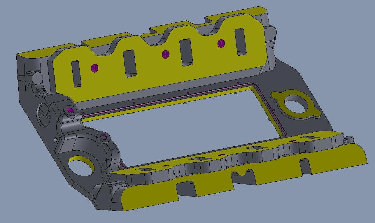
According to the CAD program the raw casting will be about 32 pounds, which is way heavier than I wanted it to be, but it turns out that those flanges that the 351C manifold bolts to add a lot of weight to the raw casting. Once the machining is done the manifold should come in around 25 pounds.
Shown below is the water jacket core, which turned out to be a lot more complicated than expected:

Lots of stuff going on around that part of the casting, including two sets of manifold bolts, port locations, and the distributor location, making it fairly complicated. But at least its done now and according to the 3D model everything fits.
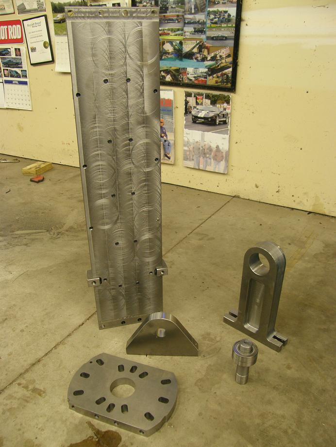
While the designer was finishing up the 3D model I've been working on a machining fixture for the manifold castings. A couple months ago I purchased a big rotary table for my new CNC machine, that can be set up on its side and will rotate a part with 0.001 degree accuracy. I wanted to couple this with with a trunnion table, which bolts to the rotary table and turns with the rotary table. Once the manifold castings are bolted to the trunnion table, they can be rotated like they are on a spit, to allow drilling all the bolt holes at the various angles required by both FE and 351C intake designs, plus machining the mating surfaces on both sides of the intake adapter, machining the valve cover rail, CNC porting all the ports, etc.
There are tooling companies that will custom build one of these trunnion tables, but they are generally pretty expensive (~$3K). Rather than buy one, I decided to buy about $500 in steel and do it myself. I found some pictures of trunnion tables online and kind of used them for the basic ideas, then drew up the table in my CAD program. About four weeks ago I started machining this stuff. The material I selected was cold rolled steel, and the trunnion table itself was over 3 feet long. I found out right away that machining long sections of steel was rather tricky; for example, when I tried to face a 1" X 8" X 38" piece of cold rolled, just taking off about .020" from one side caused the whole thing to warp signficantly. I had to go back and forth, one side to the other, taking off a little less each time, before I finally got the piece reasonable straight within a few thousandths. As I encountered this problem I did a little more research, and found that I probably should have purchased cast iron for this job; cold rolled steel apparently has a lot of stresses inside from the rolling process, and as soon as you start machining it these stresses will start warping the material. Cast iron doesn't do that, and so would have been a superior material for this purpose. But finally after a lot of screwing around, and sizing down the original table thickness somewhat to allow for the machining requirements, I got the main table completed. I also had to machine some 2" X 1" steel bar in about the same length to use as supports for the bottom of the table; I wanted to be able to mount the manifold castings on the table, but also a vise for some operations, and so the table had to be very rigid.
Finally this weekend I got this project finished up. I have been machining on this thing in most of my spare time for the last several weeks, and am relieved that it is finally finished. I still have to mount it onto the rotary table, and then finish machine the top surface once it is mounted on the CNC machine. But the tough stuff is all done now; here are some photos:
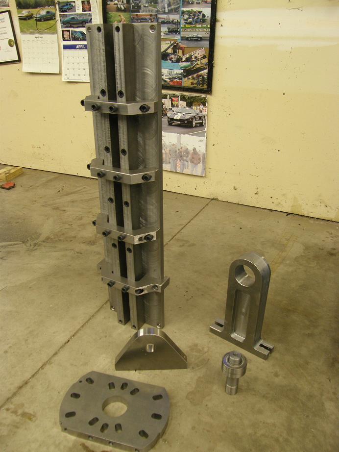
I'll post another picture of the whole thing mounted on my CNC machine in the next week or so. I plan to start using it right away, to machine the CVR water pump adapters for FE engines. On the FE intake adapter, I expect it to be another 6-8 weeks before the patterns are completed, and then I can have a foundry start pouring the first parts. That'll be fun 
The water cross-over core would give a Patternmaker nightmares,

. Why some many compound angles when 'radiusing' (such a word? LOL) would seem to be simpler. I understand the angles needed for the bolt bosses, but a Wood Model Moldmaker could 'whittle' a prototype if there weren't so many compound angles, especially in the 'tunnel' portion of the cross-over, just a thought from an old foundry worker who's seen a gazillion cores, lol, Rod. OOPs, maybe those lines represent radii, nevermind


 .
.
 , thanks, RodC. BTW, photos would be nice too.