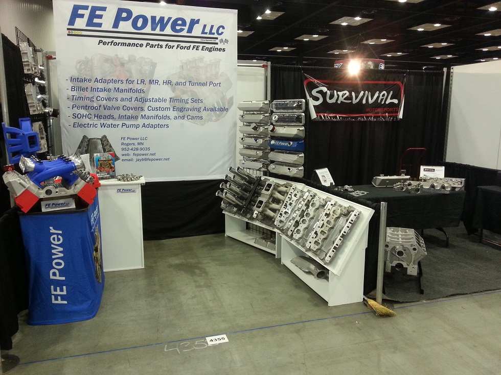
Once again this year FE Power is exhibiting its products at the Performance Racing Industry show. Prior to this year's show Barry R and I talked about getting our two booths set up next to each to provide a sort of hub for the FE faithful. We worked with the PRI folks and were able to make this happen. This year we made it into the main convention hall; my booth is #4355, and Survival Motorsports is right next door. Should be lots of fun hanging out with Barry and Marc during the show:
I've been spending most of my time over the last few months working on my cylinder head project. Because of the substantial changes I've made to the basic head design, its not just a head project; it involves the intake adapter, three different intake manifolds, and a whole new rocker arm system. I'm please to report that the head design is basically finished, after some significant modifications from the previous iteration. The water jacket design was an extremely challenging part of this work, and took me 3-4 weeks all by itself. Also, in addition to the basic head design, I have designed the sand cores required to get the heads cast, and I expect to have the first two prototype castings at the end of January (In fact it should be sooner, but with the holiday shutdowns at the foundries and core shops I'm hedging my bets on the date).
I fully expect the first prototype heads to have some unanticipated problems, but having the first couple of prototypes will allow me to get the machining programs dialed in, even if there are problems. And any required design revisions go a lot faster than a ground up design, plus the foundry I'm working with on these heads has been pretty quick on the turnaround, so I'm hopeful that I can have some heads to run on an engine by this spring.
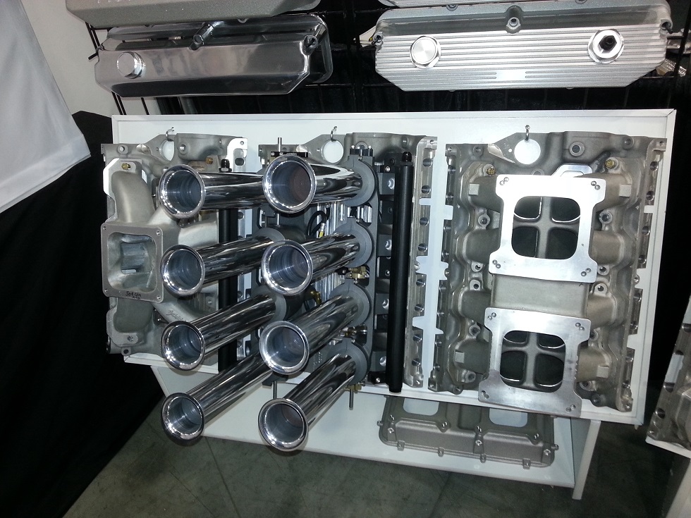
Of course in addition to the heads, I'm been working on intakes. The intake adapter has already been designed and manufactured; it uses my basic high riser and tunnel port casting, but has a different port configuration that either of those. It also has a valve cover rail that matches the heads, and is actually higher than a high riser valve cover rail, but uses the same valve cover rail angle as a medium riser. For manifold tops I've designed a billet 2X4 intake, a single 4 Dominator flange intake, and the new design shown in 3D printed form in the photo below, an individual runner crossram style intake. This intake is designed for street applications, and is EFI only. One of the design constraints was to keep it under the hood of a 67-70 Mustang (because I want to put this setup on MY car ;-)). Right now a stock distributor won't fit, but I'm considering machining a special distributor just for this setup. Otherwise, individual coil packs can be used. In any case this will have to be a crank trigger setup, because any new distributor will have to be low enough to clear the runners and this will make it difficult to fit a triggering or advance mechanism into the distributor. As shown, the intake will not allow the hood to shut on my 68 Mustang; the front four ram tube bells hit one of the supports in the hood. However, a smaller bell on the ram tube will solve this problem. I also have to move the injector mounts down a little, so that the fuel rails will clear the hood at the front. But other than that, this intake system will fit. Imagine popping the hood on your car to see something like this:
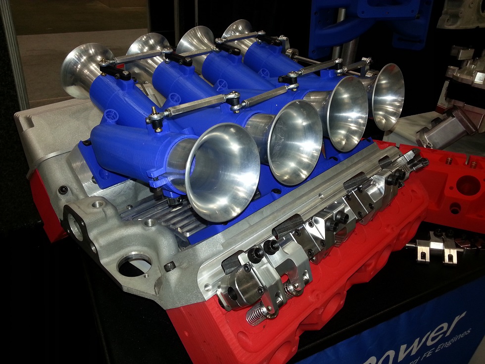
Also towards the back of the photo above you can see part of the 3D printed single 4 manifold that will also work with the intake adapter and these heads.
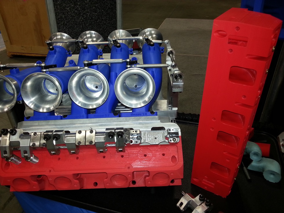
Lastly, I have the rocker arm system finalized and the machined prototypes can be seen at the bottom of the photo above, bolted onto the 3D printed cylinder head. The rocker system uses a very sturdy steel bar, that bolts into the cylinder head itself, and also bolts into some special nuts that are used on the head studs. Stock ARP FE head studs are used. Bolting the bar into both the flat part of the head and into the head stud locations provides two different angles of attachment, which I think will be very strong and secure.
The rockers are in pairs, and on four individual rocker shafts. The shafts are pinned to the heads, and steel caps bolt over the shafts to hold them securely in position. Oiling is through the pushrods. The intake ports on the heads are straight in like a tunnel port head, rather than hooking in like a normal FE wedge head, so the intake rocker has a very large offset in order for the pushrod to clear the intake port without having to go through the port like a tunnel port pushrod does. Valves are very long, over 6", and use a 5/16" stem. The rockers themselves have needle bearing fulcrums and are machined of hardened 7075 aluminum for strength and longevity.
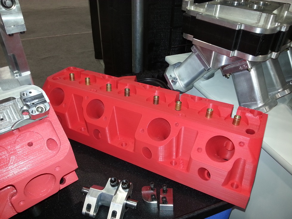
The cylinder head design has changed somewhat over the last few months, mostly to accommodate the requirements of the water jacket constraints, but also to improve the chamber. The primary difference is the spark plug location; my original design placed the plug close to the stock FE location, but to get the chamber the way I wanted it I had to move the plug so that it was more underneath the port. This gives the plug a more central location in the chamber and gets the electrode in a better position. The picture below shows the exhaust side of the head and the plug location:
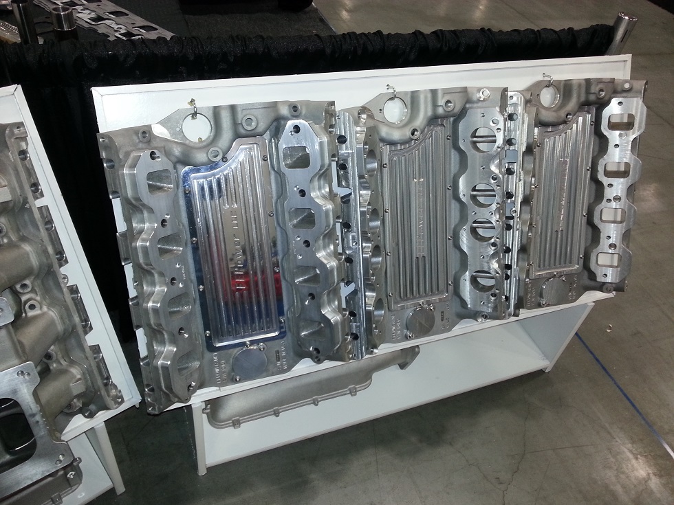
The next photo shows the intake side of the head. The ports are just slightly larger than a stock medium riser port in this 3D printed head, but I plan to do two port versions, one with a smaller port that can be run as-is or ported by someone else, and one with full CNC machining done on the ports, like the 3D printed version. I've tried to leave enough aluminum around the port so that they could be opened up even more if necessary, but the CNC ported version should be good for 850+ HP right off the shelf, so for most folks that should be plenty big. As mentioned previously, initial tests on the 3D printed head showed an intake flow of 405 cfm at 0.700" lift. This flow comes from the fact that the ports are raised a full 1.5" over a stock medium riser port location, and they are also straightened out rather than hooking in towards the cylinder wall. In addition, the valves on the heads have been moved to a better location for flow.
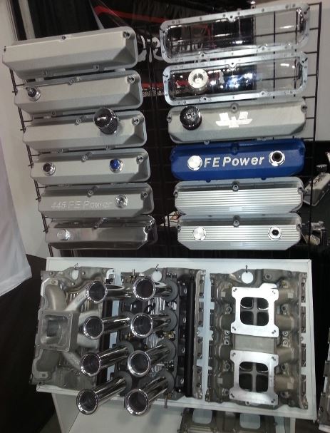
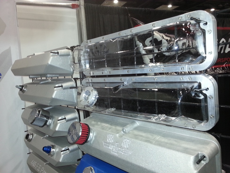
Next are a few photos of the rest of the display, for those who can't attend the show. Since my valve covers finally became available I've been able to produce quite a few different varieties, as shown in the photo below. Also, my tests over the summer of the baffle system on my clear valve covers have proven relatively successful, so I will be making those available soon. Also note the one picture below with two valve covers; on the CJ style valve cover at the bottom, you can see the spot for the screw-in cap, and the aluminum underneath that forms the baffle. The top valve cover is not easy to see, but it is my first pentroof style clear valve cover. I just got the first one successfully vacuum formed this past Sunday, after at least 15 tries. But I think I have the secret now, and if I am able to get the pentroof style clear valve covers vacuum formed reliably, I will make those available soon as well.
If you happen to be planning a trip to PRI, please stop by the booth and say hi. It's always great to put a face with the forum logins on this site, and of course PRI is a great place to talk about existing and new projects.


