Finally got my 4th axis and trunnion table setup on my CNC machine, so over the last week I've been working on trying to make adapters for the 55 gpm CVR electric water pump to fit on the FE. The four day weekend that is ending today has been a big help on this. After starting on the drawings last weekend, this weekend I got to work on defining the actual machining operations. I had to start with some pretty large stock to build these things, 6061 aluminum blocks that are 3" X 4" X 5"! As I made up the drawings I tried to determine the best way to machine the part, and concluded that I could start with the block in the vise and machine some of the adapter, but then I would need a fixture to finish them up. Here's a picture of the start, with the block clamped in the vise and one end of the block machined for the shape of the right side adapter that bolts onto the engine block:

The photo shows the end facing out, but during the machining operation the trunnion table rotates up 90 degrees so that the holes are facing up, allowing me to machine those and also to finish machine the outside surface.
Next I spent the better part of the day building the fixture for the right side adapter. This was simply a set of vise jaws for the vise that had the shape of the machined end of the block cut into them. I wasn't sure exactly how this was going to work out, but it came out pretty good in the end, and the jaws do a really nice job of clamping the part securely. Here's a photo of the partially machined block clamped in the custom vise jaws:

With this finished up I was able to start programming the remaining machining operations on the right side adapter. This took the better part of a couple of days, and I made some mistakes along the way, but overall for a first prototype the part came out looking pretty good. Here's a couple of pictures:


And here's a shot showing the adapter bolted onto the CVR pump that fetorino was kind enough to send to me when I started messing around with this project:

Note that there is one small piece of the adapter that is bolted in place on the main block. This piece is there to provide one of the mounting holes for the stock Ford triangular alternator mount bracket. I decided to make this from a separate piece of material, because if I had included this as part of the original piece of billet aluminum, I would have had to start with 4" X 4" material, instead of 3" X 4". The 3" X 4" aluminum bars are expensive enough...
Next I decided to mock up a normal Edelbrock water pump on an engine, along with the factory alternator brackets, and then remove the Ed pump and bolt on the CVR assembly to see how the fit was. I haven't been working with any blueprints here, just measurements, so I expected to be off a little on some of the bolt hole locations. So, putting the Ed pump on first and getting all the brackets tightened before swapping in the CVR adapter and pump seemed like a good way to check everything. Here's a photo of the Edelbrock pump on the engine:
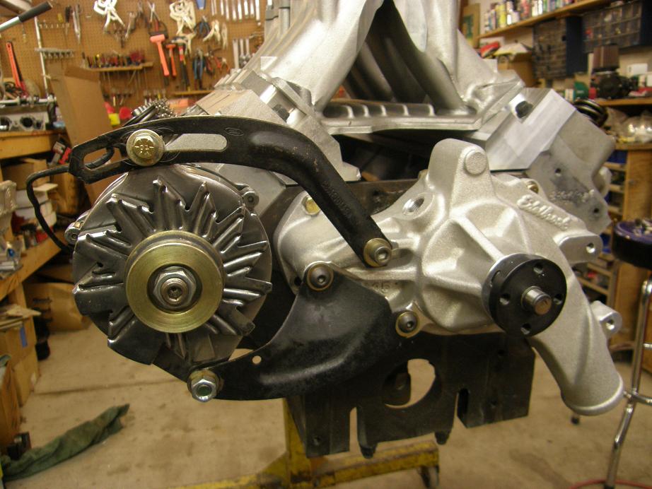
When I bolted on the CVR pump and adapter I was pleasantly surprised at how close the mounting holes were. One hole should really move down about .050", but other than that everything lined up beautifully. I did run into one unexpected issue, though, and that was interference between the CVR pump and the factory triangular bracket. In order to make the factory bracket fit, I needed to file a small notch in the bracket; you can see it near the lower right bolt hole of the triangular bracket in the photos above and below. Seemed like no big deal, though, and the bracket is still perfectly functional. I also could have machined a corner off the CVR pump itself to allow the factory bracket to fit without interference, but since it isn't my pump I decided I'd better not do that


Here's another shot of the area behind the pump with a Shelby timing cover installed. I assume that the standard Ford timing cover will also fit, but I need to check that to be sure before I finalize the design. But in any case, there is clearance from the back of the CVR pump to the timing cover:

Finally, just to check the front extension of the CVR pump as compared to an Edelbrock or stock pump, I bolted the Ed pump to the left side water pump mounting hole and took the picture below. The Edelbrock pump sticks out about 1/2" farther than the CVR pump, so there should be no concerns about the CVR pump being too close to the radiator:

I need to make a few minor modifications to the machining programs, but the right side adapter is pretty much complete at this point. For the left side adapter I have to start from scratch again, making the drawing, machining the block, and then making up a second set of vise jaws for fixturing the left side so the machine work can be completed. This will take me at least another couple of weeks to get finished, but hopefully by the end of January I can be manufacturing these things for people who may want them. It will be nice to have a 55 gpm electric pump available that bolts onto the FE...


