I apologize for taking so long to post this information; the dyno tests were completed over
a week ago, but its taken some time for me to get the data organized and written up. But,
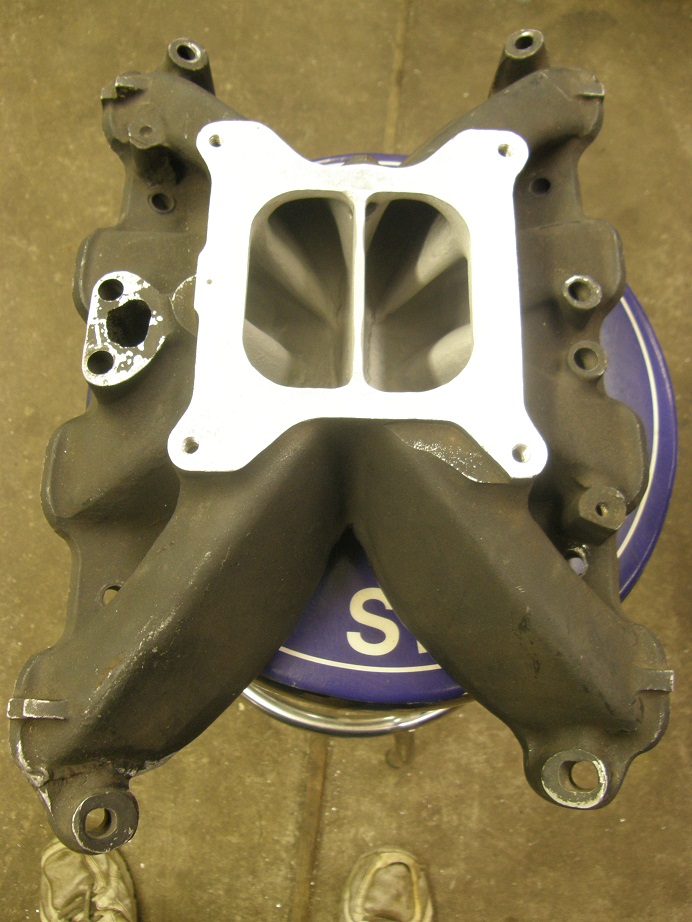
here it is. I started a couple weeks ago with another Edelbrock Torker, this one sent up to
me by Joe Craine, that had a plenum divider welded in. Joe got this intake in some kind of a
trade, and I assume that the plenum divider was an attempt to build low and midrange torque.
Here's a picture of the intake:
I ran the dyno tests and bottom line was that the plenum divider didn't help at the lower
engine speeds, but it gave up a lot at the higher speeds. Here are the two dyno pulls showing
the comparison between the stock Torker and the one with the plenum divider:

Obviously, on this engine the plenum divider was no help.
Our forum member Dumpling made the trip to my shop and brought two very interesting manifolds
to test. One was the Bud Moore boxram, and the other was an Edelbrock Scorpion. I was very
keen to test the boxram; I'd never even seen one in person and was looking forward to seeing
how it did on this engine. There were two tops available to test this manifold with. One
was the factory top for a 4150 series Holley carb, and the other was a custom top to fit a
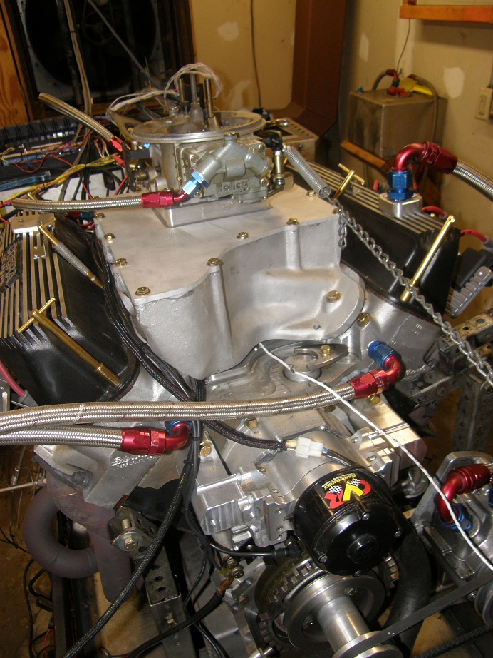
Dominator carb. We planned to test both. After a quick cleanup we got the base of the intake
bolted onto the intake adapter. Here's a picture:
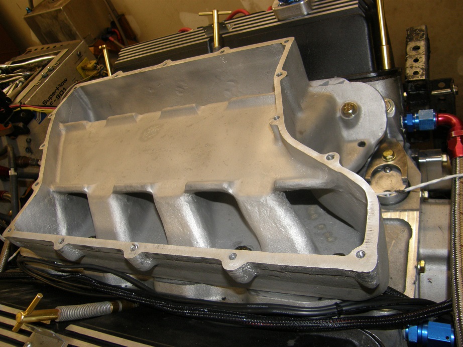
All but two of the manifold attachment bolts are located INSIDE the manifold. I made sure we
had good thread engagement on all of those LOL! The original top had been modified to add a
plenum divider below the carb:
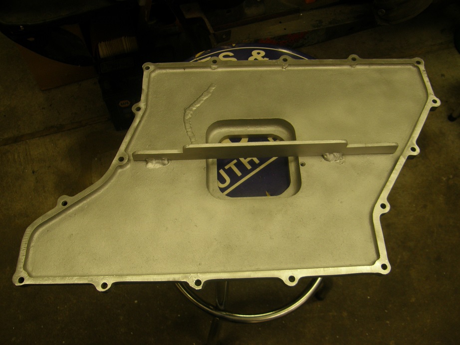
Since this was a high RPM manifold back in its day, I'm not sure what whoever did this was
trying to accomplish, but we were going to run it this way. After getting all 16 bolts in
place to hold the top down, the engine looked like this:
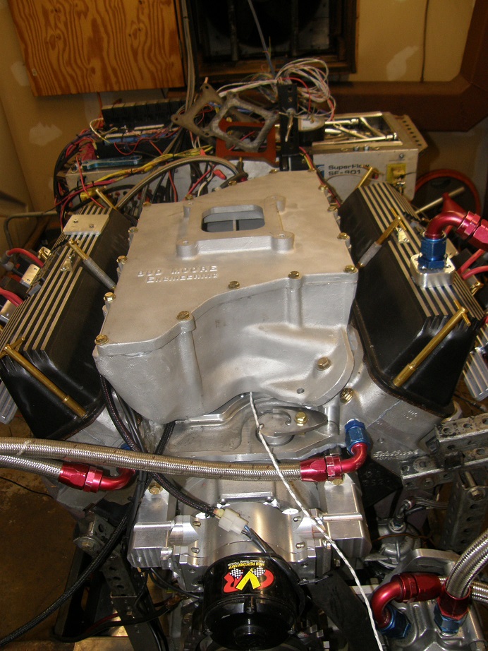
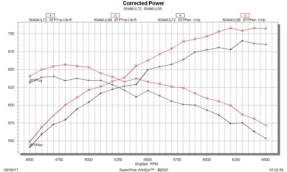
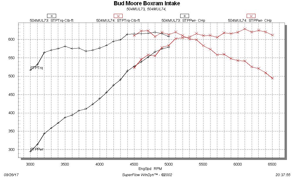
NASCAR, here we come! After installing my 1000 HP Holley carb, we ran the pulls. Pretty
disappointing for such a cool old intake. Peak HP was only 628, nearly 100 HP lower than
the best numbers from this engine. Here is the low RPM data and high RPM data put together on
a single graph:
Hoping for better results, we swapped on the custom top with the Dominator flange. But this
top was flat, and without the spacer built into the factory top, the shelf in the middle of the
manifold looked like it could actually impede the opening of the carb butterflies. That is one
obvious issue with this intake; as soon as the air/fuel mix comes out of the carb, it has to
make an immediate, hard 90 degree turn to get to the runners. Dumpling had brought a 1"
Super Sucker spacer to use with this top, so we installed that and bolted on the carb. Here's
how the engine looked with this setup:
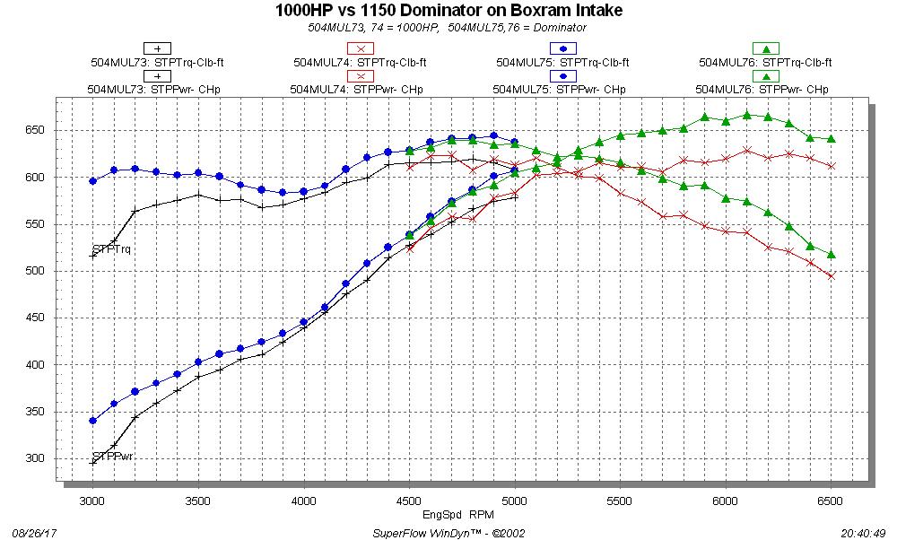
We ran the pull, and what a difference the carb made! The engine picked up almost 40 HP
at peak, and was better all across the operating range with the Dominator carb. Here's the
data for both carb setups, on the same graph:
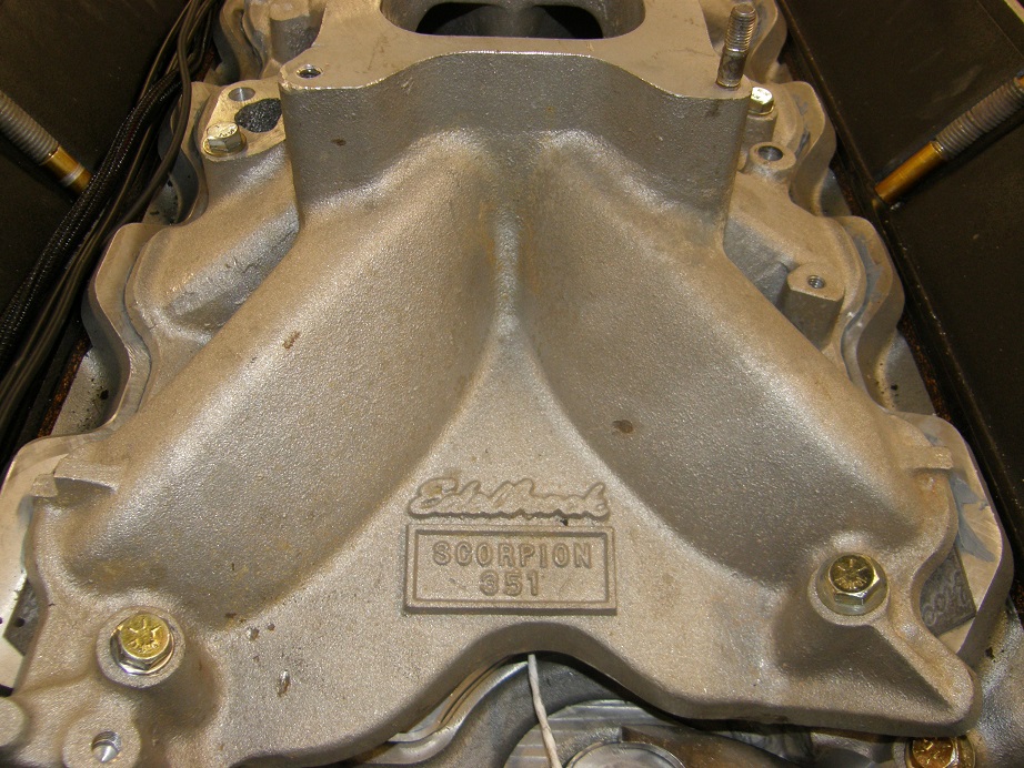
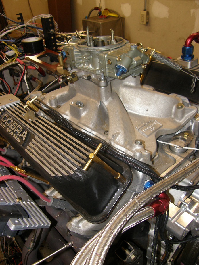
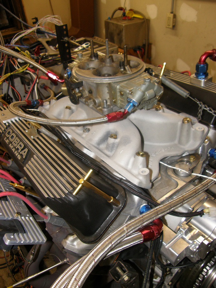
Satisfied with our results from the boxram, we went ahead with the next intake, an Edelbrock
Scorpion. This intake appears to be nothing more than a Torker, with a cast-in 1" open spacer.
Here's a couple of pictures of this intake on the dyno:
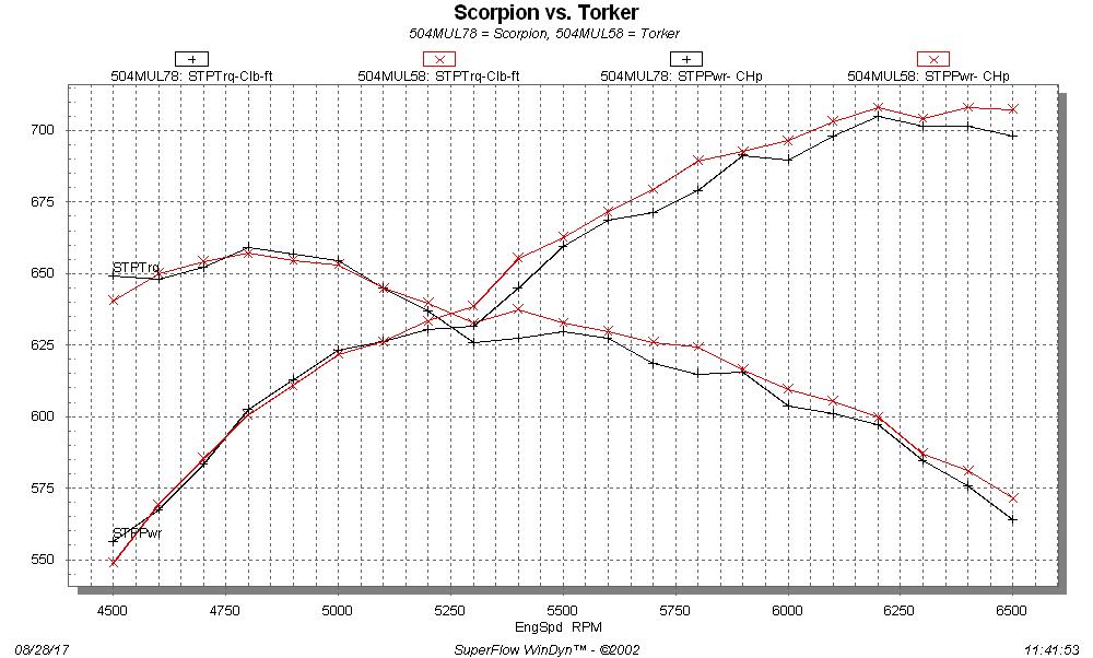
With the 4150 carb, this intake behaved nearly identically to a standard Torker, making just over
700 horsepower. It was down just a little across the RPM range, but not much. Here's a graph
of the high RPM pull, with the standard Torker included:
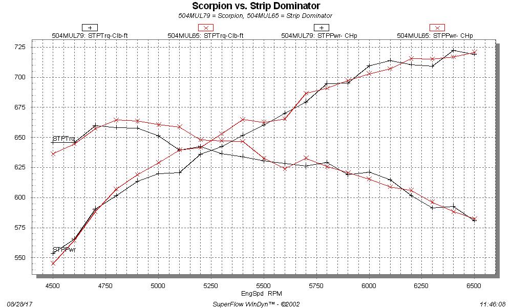
Despite running a little short on time, we decided to install the Super Sucker 4150 to 4500 spacer,
and the 1150 Dominator carb. This combination had made almost no difference on the standard
Torker, and that was what I was expecting here. Once again though, I was surprised by the
result; the Scorpion picked up a lot on the top end, rivaling the performance of the Holley Strip
Dominator. The graph below shows the Scorpion and Strip Dominator on the same graph; they are
really, really close:
Once again thanks to Dumpling for bringing up these very interesting manifolds to test.
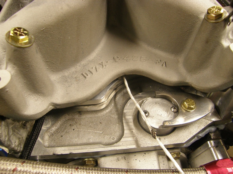
After a break of a few days I got back to testing with a factory 351C D1ZX aluminum intake, sent to
me courtesy of our forum member mtburger. This intake is set up from the factory with a
Dominator carb flange. Some pictures are below:
Since it was already set up for the Dominator I didn't bother with the 4150 on this intake, and
just ran the 1150 Dominator. First testing was with the carb bolted directly to the intake, and
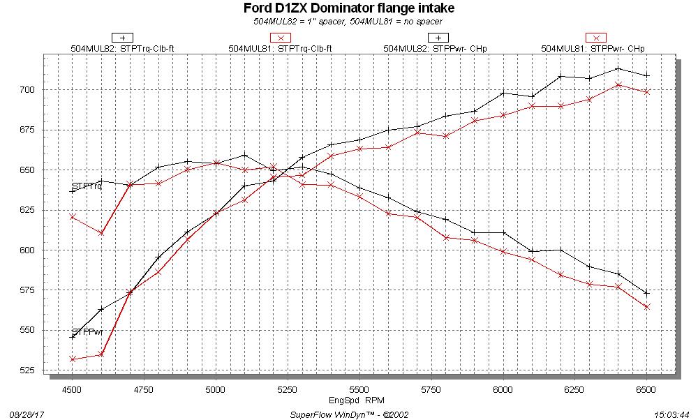
this intake did very well, peaking at 703 HP. After the initial tests I tried it with a 1" Super Sucker
spacer, and this picked up the manifold even more, about 5-10 HP across the upper RPM range. The
graph below shows the results with and without the spacer:
Great performance from that intake. Next I stuck the Offy tunnel ram back on the engine, so that
I could test it with the 4150 to 4500 Super Sucker spacer. I was hoping for better results with
that combination than what I got with the plain spacer previously. However, it turned out that
the engine liked this combination even less:
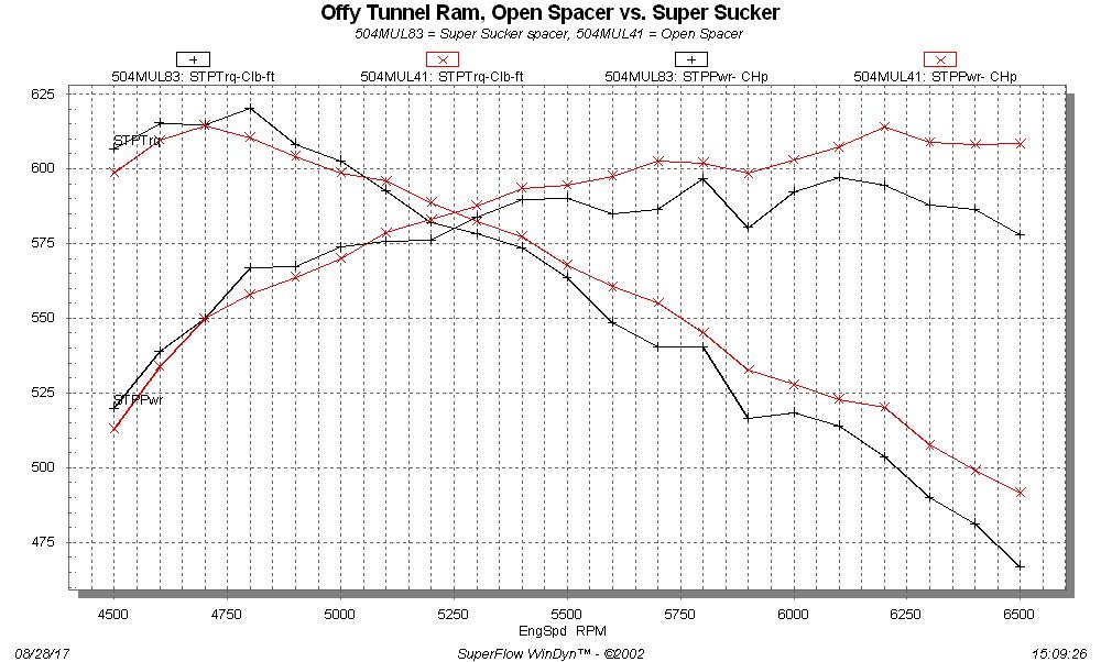
This is the second time I've seen an engine not like the Super Sucker spacer; the last time I saw
this was on Royce's MEL engine, and it was also equipped with a single 4 tunnel ram. I think that
for some reason, the Super Suckers don't work well in that configuration.
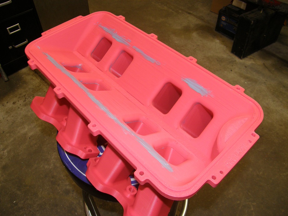
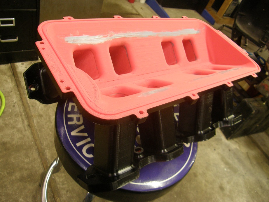
For my last test with carburetors (for now), I bolted on my 3D printed intake. I was really looking
forward to this test, but also was quite concerned about air leaks. There was no guarantee that
the 3D print was airtight, and in some places it was quite thin. As a result I re-printed a couple
of the runner sections to make them a little thicker. I also found some strands of plastic coming
loose inside the plenum, so I smeared some TA-31 over those to keep them in place. I also took
the time to spray the outside of the intake with a couple heavy coats of black paint, to try to
give the intake every chance to seal. Here's a couple of pictures of the intake with the sealer and
also the paint on the outside:
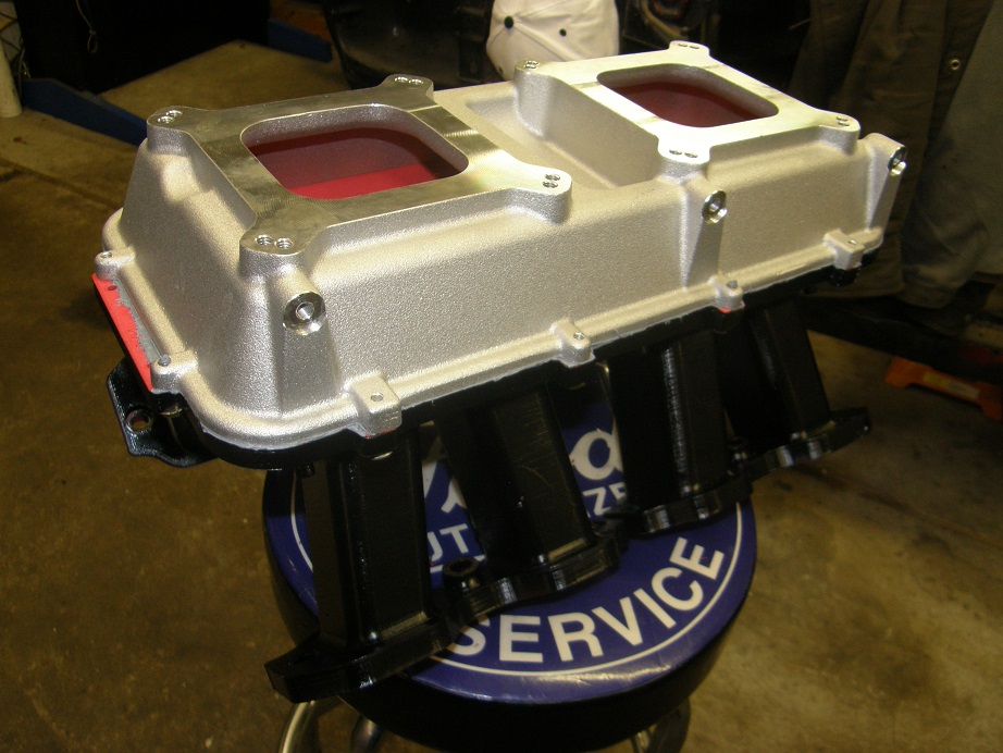
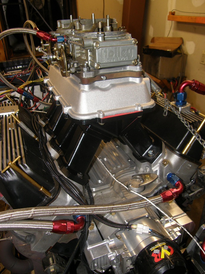
After getting the intake as ready as possible, I bolted it on to the engine for a trial test. For
carburetion I used the two 660 center squirter carbs that I had run on the Weiand tunnel ram at the
beginning of work on this dyno mule. Holley makes an LS top that allows bolting on the two carbs;
here's a picture of the intake with the top, and also the complete setup bolted on the engine:
The moment of truth had arrived. I started the engine, but it would only fire for a moment and then
it would quit. I experimented for a while and did manage to keep it running at around 2500 RPM for
a few seconds, but vacuum was nonexistent and the engine was running super lean. Obviously, I had
a severe vacuum leak, which was what I had been afraid of. No way I could run the engine like this.
However, when I pulled the intake off the intake adapter, I found that the problem was different than
I had expected. It turned out that when I tightened the plastic manifold down, the bottom of the
ports had curled up, so that I had no seal on the bottom half of the intake ports. In fact, on one
port I measured a gap of nearly 1/8" between the plastic runner and the intake adapter.
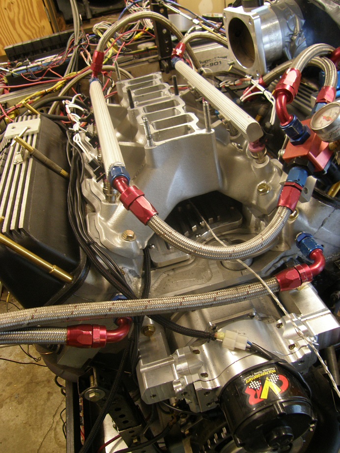
At this point I went on to do the EFI manifolds, but after that I came back to the 3D printed intake
to try again. This time I didn't tighten the plastic manifold down so much, and also used a thick
bead of TA-31 around the bottom of the ports to make it seal. However, when I was done tightening
the intake I found that another problem had surfaced. The runners of the intake are held to the
plenum with screws, and the plastic threads in the plenum were pulling out, allowing the plenum to
separate from the runners in several spots. Again, an obvious potential vacuum leak.
The solution to this would have been to drill the attachment holes in the plenum all the way through,
and put a through bolt, like a small carriage bolt, through the plenum from the inside with a nut
on the outside. This would have been a fairly time consuming project, though, and my friend Royce
had arrived with Honest Abe, his Lincoln Y-block for Engine Masters, and he needed to get the engine
on the dyno. So, I ended up pulling the 504" dyno mule off the dyno without having had the opportunity
to test the 3D printed intake. I will get the changes described above made so that I can test it
when the mule goes back on the pump.
So, backtracking just a bit, it was time after the first go-around with the 3D intake to test the
EFI intakes that Joe Craine had sent up for me. These are two piece Trick Flow intakes for the
351C, one piece for the main runners and the other an interchangeable top. Joe was kind enough to include
both types of tops, one of which has very long runners built in, which I assume are designed to
generate lots of low end torque, and one which is basically an open plenum. Joe also sent up a
couple of throttle bodies for the intakes, along with the fuel injection rails, so that
all I had to do was install the fuel injectors and the fuel system, and wire up the throttle bodies
into the EFI system.
The throttle bodies that Joe sent up were rather small I thought at 65mm and 75mm, and in addition
the throttle position sensor connectors were a type that I didn't have on hand. So, rather than start
with those, I used one of my own throttle bodies, a 90mm Wilson that had a connector that worked
with my wiring harness. After looking at these issues and deciding how to proceed, I got to work
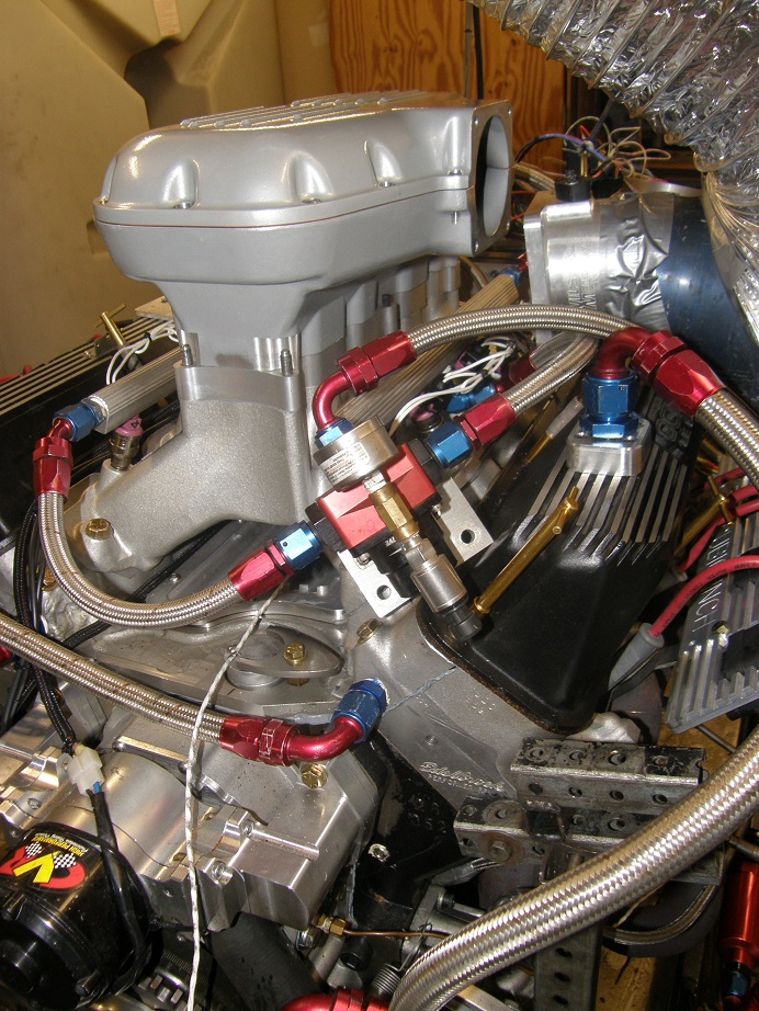
installing the intake. Here's a picture of the engine with the TFS base installed:
I decided to test the box style plenum first; here's a picture of it on the engine:
Royce B was up with his Engine Master's engine by this time, so he pitched in to help me with the
dyno work. Soon we started the engine and began tuning. These were different fuel injectors
than the ones Marc H had brought for the previous EFI test, so we ran several pulls to dial in the
A/F curve with these injectors, and with this intake setup. Once we had the A/F correct I ran both
the low RPM pull and high RPM pull back to back; they are shown together on the graph below:
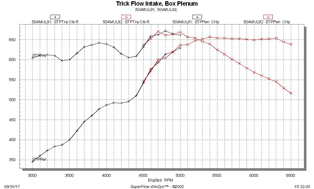
Peak torque with this setup was excellent at 670 foot pounds, and average torque in the lower RPM
range was excellent. But the torque curve was on a real roller coaster ride up to 4500 RPM.
Horsepower was only just above 650 HP, but it was flat almost all the way to 6500 RPM. Manifold
vacuum was up to an inch at the end of the pull, indicating that an even larger throttle body
would help the power output. In light of that there was really no reason to test the smaller
throttle bodies.
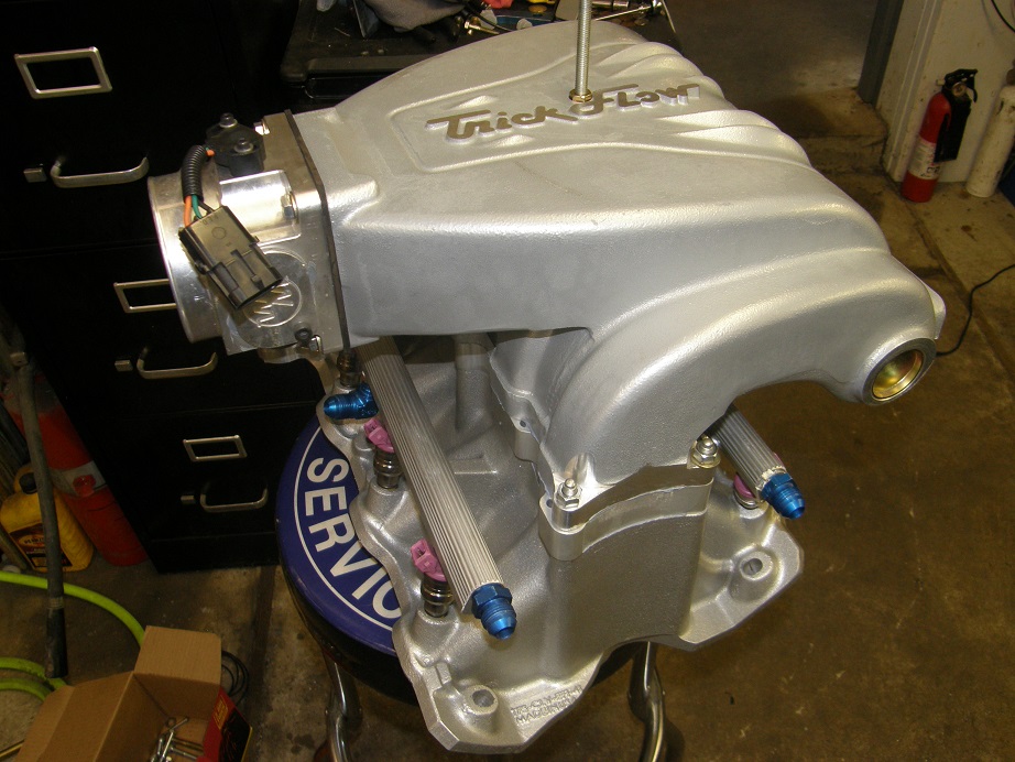
Next we installed the long runner plenum. Here's a picture of it assembled to the base and ready
to be installed on the engine.
Looking at this setup I was concerned that the torturous path that the air had to take would impact
the ability of this induction system to make good power, and it sure seemed that way from the dyno
results. This intake was smoother at the lower engine speeds than the previous one but fell off
pretty dramatically at the top end. Here's a picture of the low RPM pull and the high RPM pull from
this setup on the same graph, and then put together with both pulls from the box style plenum on
the following graph:
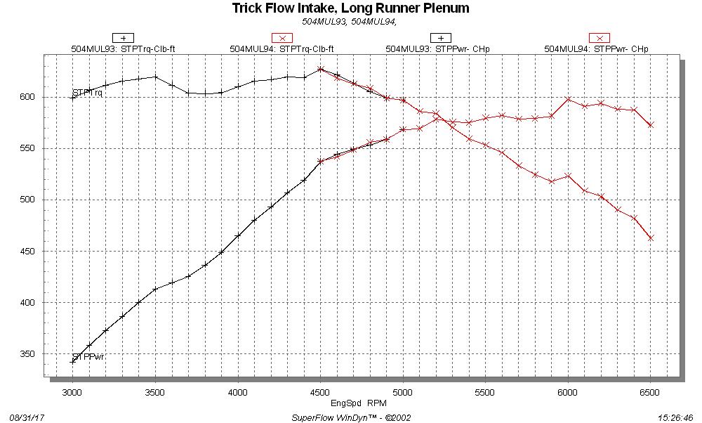
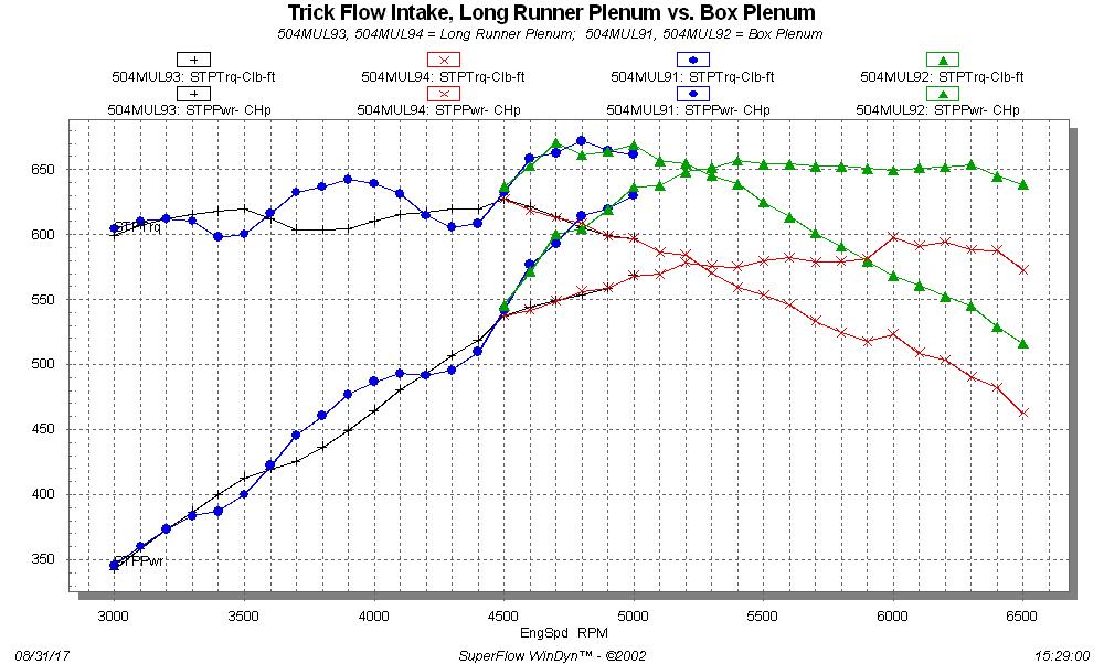
At least for this engine, the box style plenum seemed to be far superior.
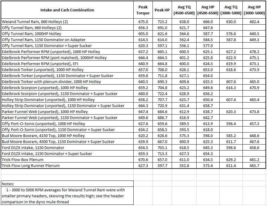
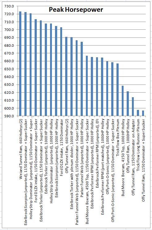
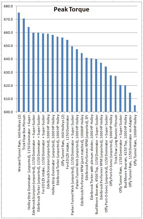
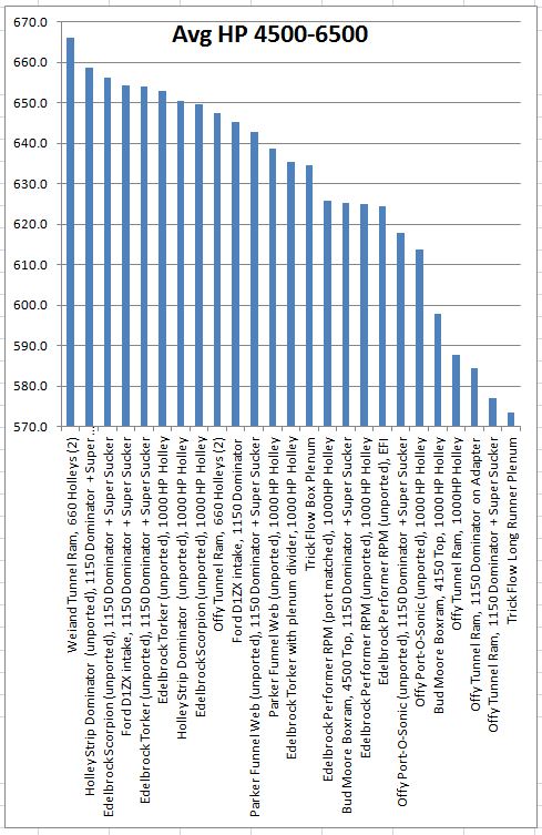
That pretty much covers all the dyno testing I'll be doing for a while on this particular mule. I
have plans to do more testing in late fall or early winter, with a few more intakes, and will post
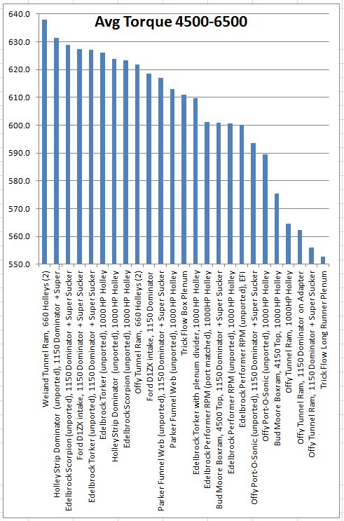
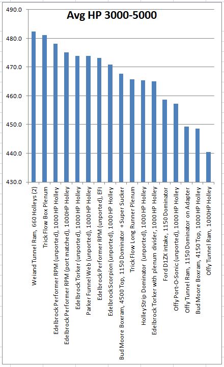
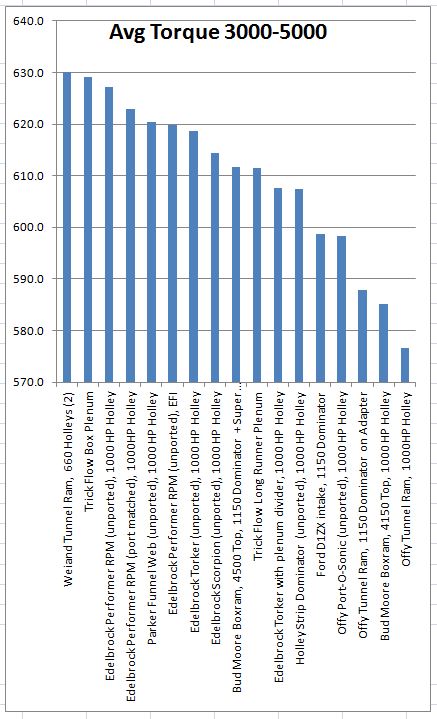
in this thread when those tests happen. In the meantime, I have updated the table below with all
the results, and have also included some graphs showing all the intakes and how they performed in
the different parameter areas (Peak HP, Peak Torque, Avg HP 4500-6500, Avg Torque 4500-6500, Avg HP
3000-5000, and Avg Torque 3000-5000). Hopefully this will allow someone with one of my intake
adapters to make a good manifold choice when running it on the engine.