Quite a while back I started looking at doing a billet intake manifold for my intake adapters; see the thread below for some background information on this:
http://fepower.net/simplemachinesforum/index.php?topic=2551.msg24837#msg24837As it happened one of my customers contacted me about doing one for a tunnel port intake manifold, to be used in a centrifugal supercharger application. With only a bare minimum of intake manifolds available for the tunnel port, and the fact that the tunnel port runners could come straight up out of the heads, I thought that this would be a good intake manifold to start with when I had time to do this project. So, late last year I got going on this, and made the following model in Solidworks:
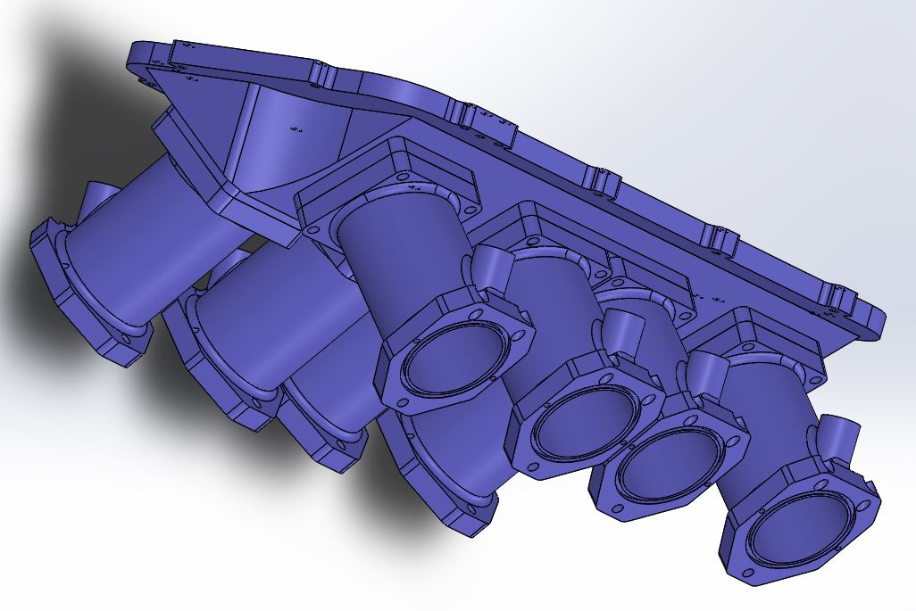
This billet intake will be for a fuel injected application, so all of the runners will be machined for fuel injectors. All 8 of the runners are the same, which simplifies design and manufacturing; another reason why a tunnel port intake is a good one to start with for me. The runners bolt to the plenum, and seal to the plenum and the intake adapter with Viton O-rings. In addition to the billet intake, of course, the intake adapter has to be modified with some bolt holes so that the billet intake can bolt down. I decided to make the upper two holes on each runner bolt straight down, rather than come in at an angle; I figured that this would help compress the O-rings during assembly, and get the single bottom bolt lined up properly with the hole in the intake adapter.
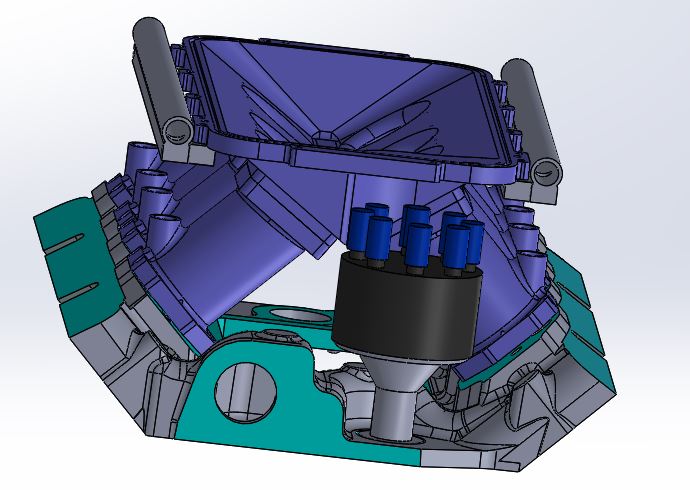
In addition to the billet intake itself, I modeled the intake adapter, the fuel rails, and the distributor. The distributor was a concern; my customer wanted as low a profile on the setup as possible, ideally to fit under the hood of his early Mustang. As a result I took a guess on how low I could make the plenum, which was going to have to overhang the distributor. The distributor cap would have to be able to come off of this setup, of course, and it looked like it might be pretty tight to me; here is the model:
I decided I probably had enough room at least for a Ford distributor (rather than an MSD), so I went ahead and got going writing programs for the machining fixtures I would need to build the billet intake. I got most of the way done with this about a month ago, right about the time that I got my 3D printer up and running. At that point, the question of whether or not the distributor could be installed and the cap removed with everything in place was still a concern. This was an especially big consideration since this manifold would be fitted with one of those forward facing throttle bodies, and it would lean over the top of the distributor just like the plenum. So, with the 3D printer sitting there, I decided it would be a good project to 3D print copies of the billet intake parts, then test fit them all together and see what the distributor clearance really looked like.
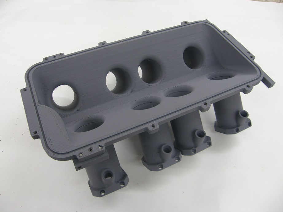
Naturally, it took some time to get the 3D printer adjusted so that it would correctly print the parts. I tried ABS plastic first, and this worked fine on the runners, but on the plenum the plastic warped after the print and didn't fit the runners well. I ended up switching to a more stable, lower temp plastic called PLA, and still had some problems, but I did get a workable plenum print out of that stuff. Here's a couple pictures of the 3D printed parts for the billet intake:
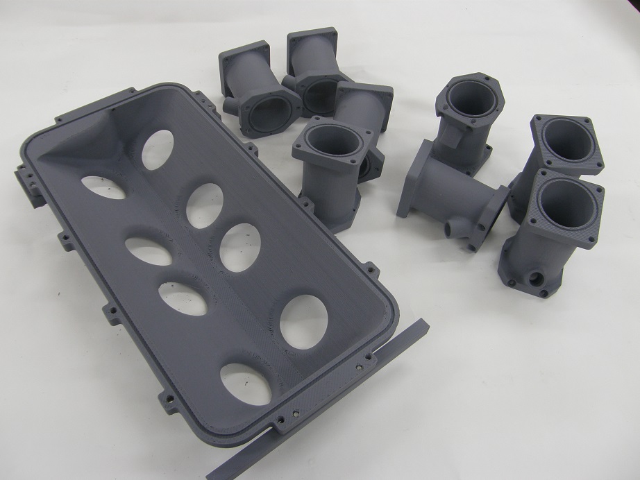
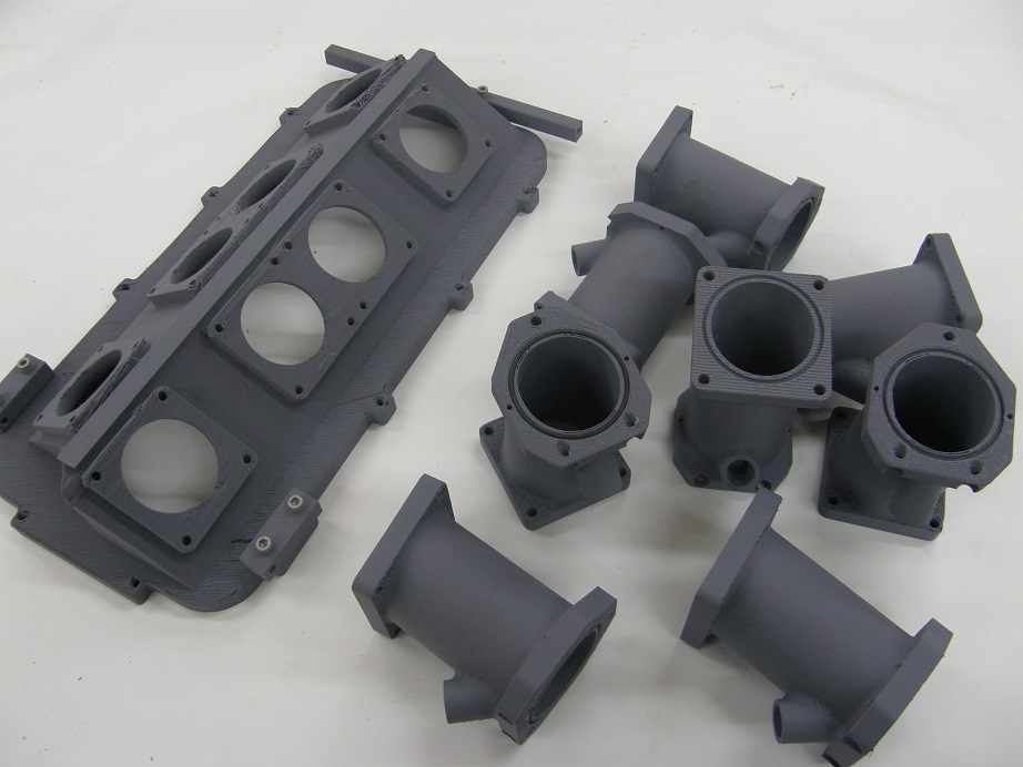
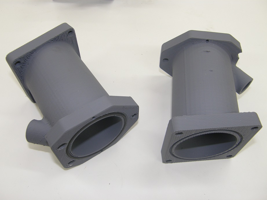
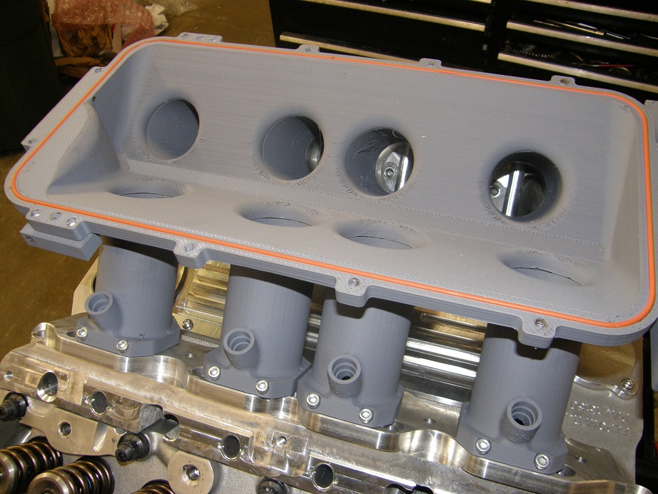
You'll notice three rectangular blocks bolted to the plenum; these were printed separately, and are used to attach the fuel rails to the plenum. A couple closeups of the runners are in the photos below. One of them has the O-rings installed:

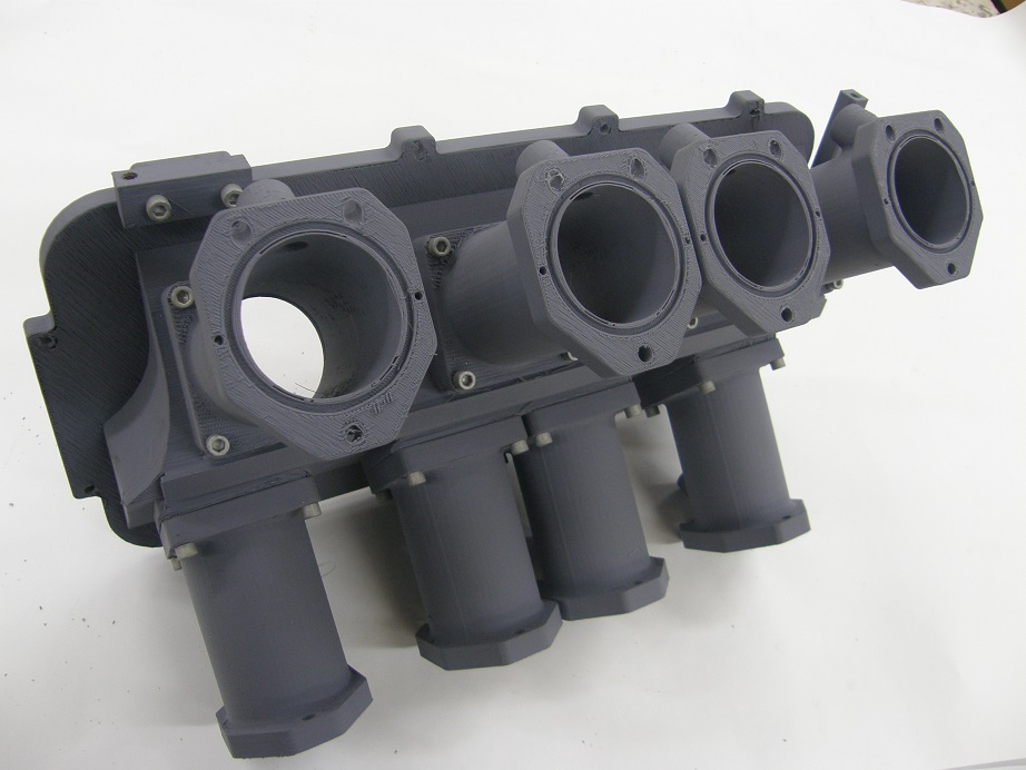
After getting the parts printed, it was time to bolt them together. The screws I used were 1/4-20, and the threads in the 3D prints were a little rough for a screw that small, so I ran a bottom tap into all the threaded holes just to make sure they would all hold the screws. The billet intake parts bolted together without any problems:
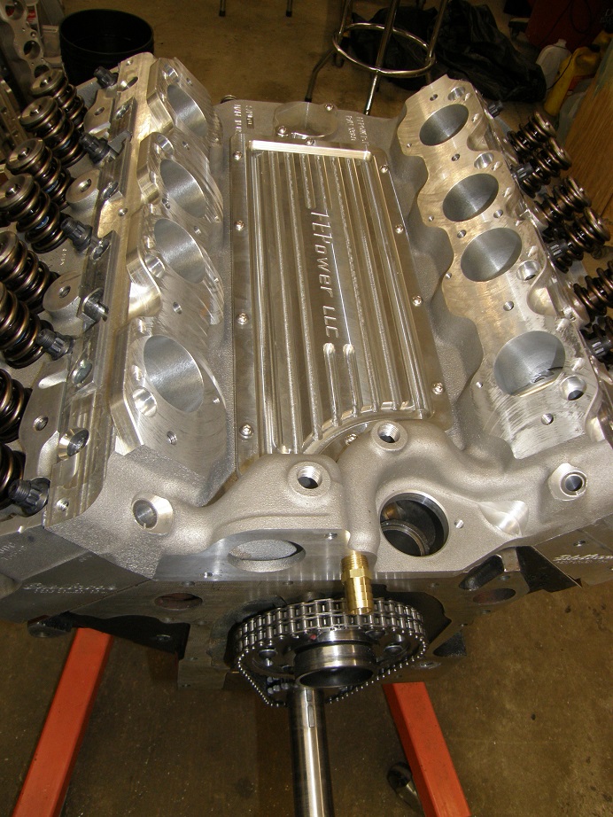
Next I had to take the tunnel port intake adapter that my customer had purchased and re-machine it for the screws required to bolt the intake on. Using the screw locations defined in the Solidworks model I was able to do this without too much trouble. Below are some photos of the modified intake adapter. I put it on a new dyno mule that I am currently building,so that I could test fit it with the distributor. Unfortunately, the dyno mule uses MR heads, not tunnel port heads, so I couldn't bolt it down, but at least it sits in the same location as it would on a tunnel port engine and will allow the distributor test fit. Looking at the vertical holes above the ports that hold down the billet intake, there is not much depth available there before breaking into the port. I was limited to about 1/4" for depth of the hole, so I machined the intake adapter to use 1/4-28 bolts in this location, to allow more thread engagement:
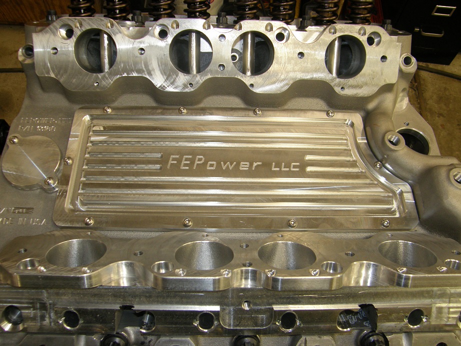
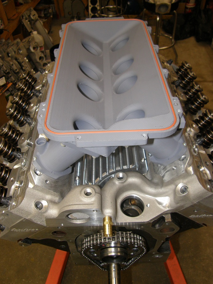
Next, I bolted the 3D printed intake on; this was a moment of truth, of course, because if I'd made any mistakes then the holes wouldn't line up, and it would be back to the drawing board. Fortunately everything came out looking good, and the intake bolted on without any drama. The bottom 8 bolt holes, one each in the bottom of each runner, were a little bit of a challenge to get to, but I was able to get them all tightened up with a 3/16" ball end hex in a socket, with a 12" extension. It will take 24 bolts to remove or attach this intake, but at least it will still be able to be removed from the intake adapter, preserving the advantages of the inspection plate in the center of the adapter. After getting the intake on, I put a rubber O-ring in the groove of the plenum; here's a couple pictures of the setup at this point:
So far this was coming together pretty nicely, and I was happy with the results. Next I decided to machine some fuel rail stock and bolt it in place with the fuel injectors I had on hand. I figured this would take me a few hours. I should know better

Three full days later, I finally had the fuel rails done. I had to machine some fixtures in order to hold the rather oddly-shaped fuel rails in the vise, and then adjust the fixtures so that I could machine both fuel rails at once (thinking ahead to when I might do more of them). Getting the fuel rails machined required two different setups, one for boring the holes for the injectors on the bottom of the fuel rails, and one for drilling the holes in the side that hold the fuel rails to the plenum. I actually still need one more fixture, to stand the fuel rails up on end and then chamfer and tap the holes for the #8 AN fittings, but after three days of screwing around with this I decided to wait on that detail. It will end up taking me another two setups to machine those threads, one setup for each end of the pair of fuel rails, but hopefully only one more fixture.
After all this screwing around with fixtures and setups, the actual machining operations for both fuel rails took about 10 minutes. How ironic

Anyway, I finally had the fuel rails ready to install. They fit nicely on the billet intake; here are a couple pictures:

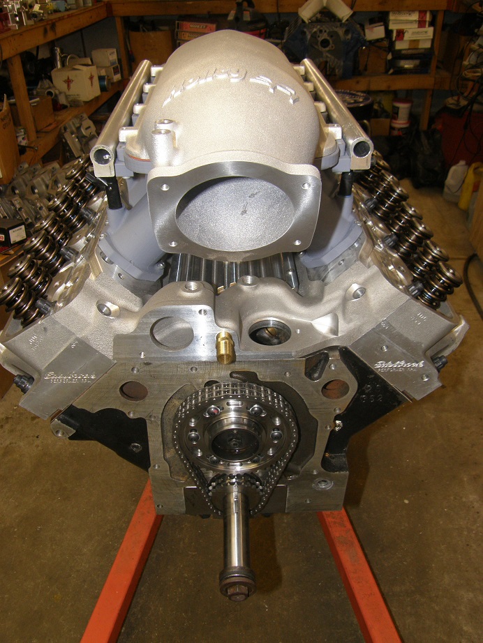
The distributor fit test was fast approaching. In order to check this fit I had purchased one of the Holley EFI tops for an LS engine, with the forward facing throttle body. My plenum is designed to use these off-the-shelf parts, which are fairly inexpensive and readily available. Here's a couple of pictures with the top installed:
Looks pretty cool! Finally, I decided to test fit the distributor. I tried the MSD distributor I had on hand first. With that big round rotor in place, I couldn't even get it to clear the top and fit into the distributor hole, but after removing the rotor I was able to drop it in. However, it was clear with the HEI style cap terminals on the cap, it would be way too high to get the cap installed. My friend Kevin is going to bring over one of the GM style caps, with the normal non-HEI plug terminals, to see if that may fit, but I think it is questionable.
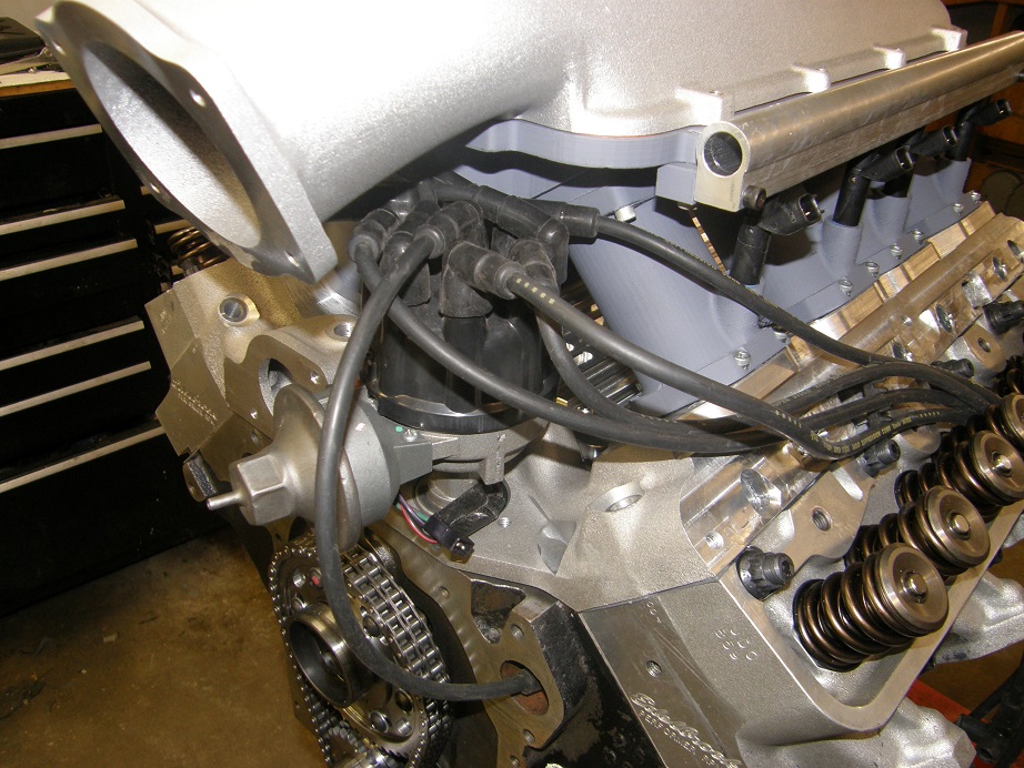
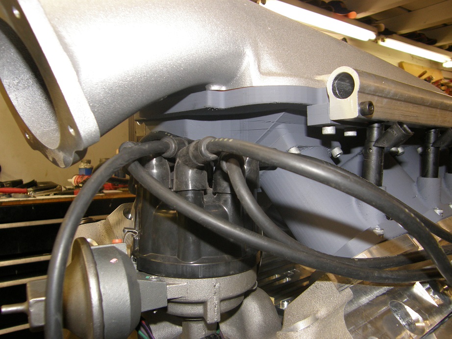
My design assumed the use of a Ford distributor, which is lower than the MSD distributor by a good 3/4". The Ford distributor dropped in with no problems, and I was relieved to see that I was able to wiggle the cap with wires into position and clip it into place. Thank goodness it fit! Here are a couple of pictures:
Now that I have confirmation that everything fits together as it should, and that the distributor and cap can be removed as long as they are Ford parts, I can get going on actually machining the aluminum runners and plenum for this billet intake. My first pass at this indicates that it will, again, take me longer than expected to write the programs, but I think at least I'm on the home stretch on this project. Once I have this completed, next up will be the same type of billet intake, but for a medium riser style engine, potentially to fit with the #13001 FE to 351C intakes that I already make available. Maybe the 351C guys will even buy some

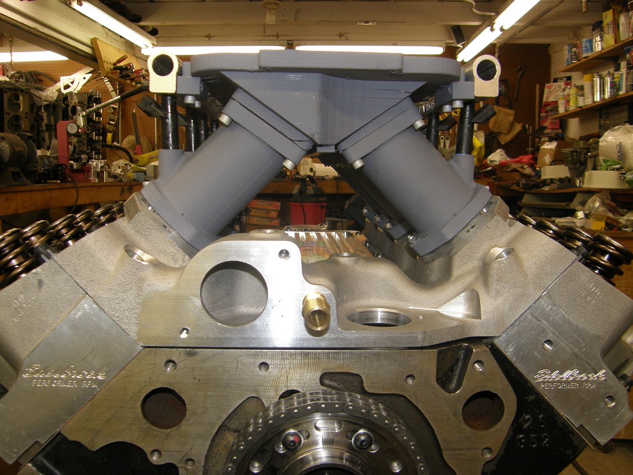
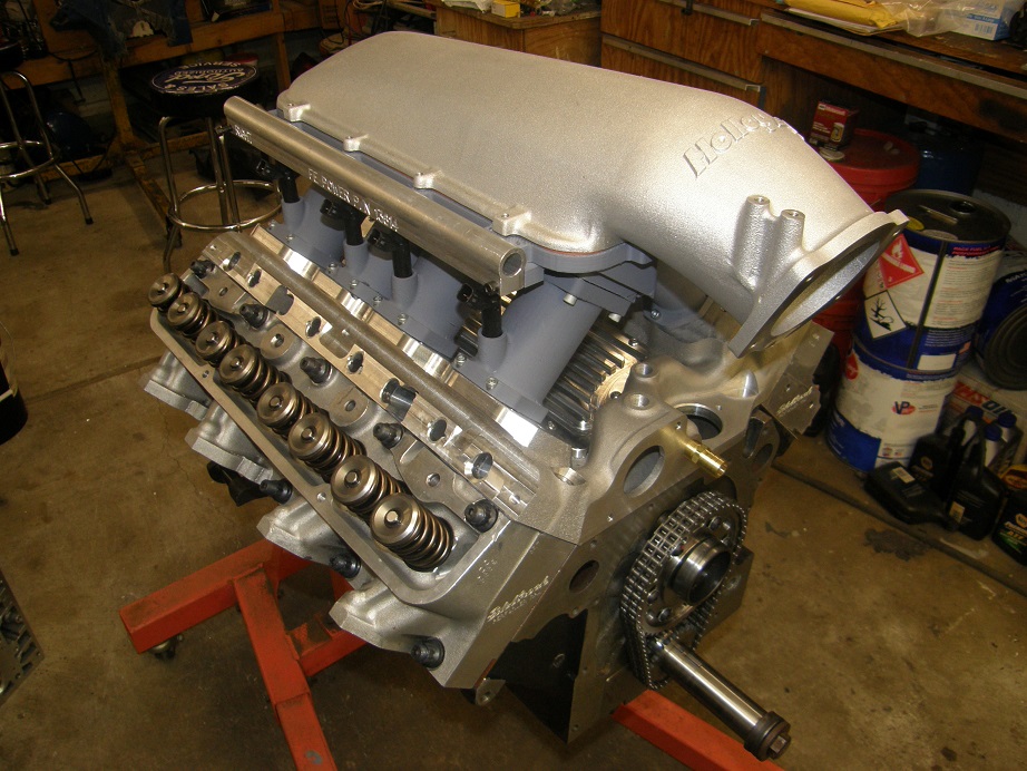
As a last step, just for fun I took one of the Holley tops for a 2X4 carb setup and put it on the engine to see how it would look; photos below:
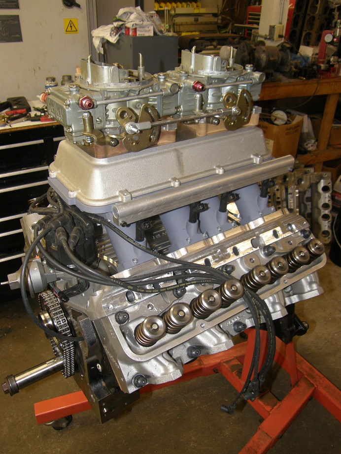
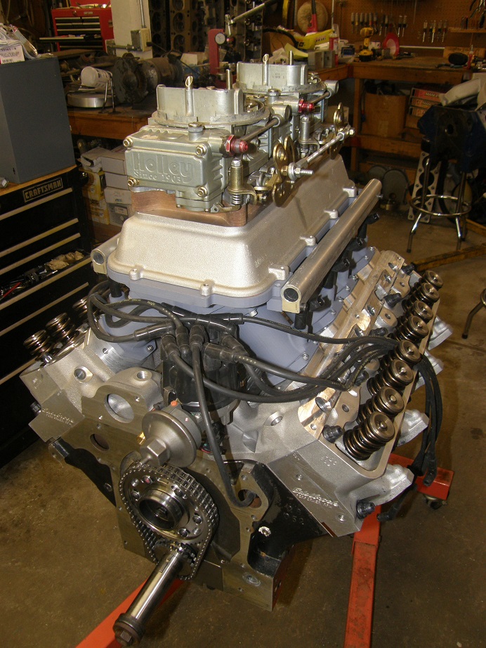
I'm not overly thrilled with the appearance of the Holley plenum, but maybe it could be customized somewhat to spice it up a little. And at least it is readily available, and fairly inexpensive. I may make a billet top for the billet intake at some point too...
I will post more in this thread as I get the parts machined for this setup.


