Author Topic: Installing an FE main stud girdle  (Read 6111 times)

0 Members and 1 Guest are viewing this topic.

jayb

  • Administrator
  • Hero Member
  • *****
  • Posts: 7407
    • View Profile
    • FE Power
Installing an FE main stud girdle
« on: July 23, 2021, 02:29:35 PM »
On my 390 stroker project in the Member Projects section I had been looking to use a main stud girdle, but couldn't find one available at the time I wanted to do it, so I went with crossbolted main caps instead.  They were expensive, and a real pain to install.  I wanted to try installing a girdle as a comparison, and it turned out that one of my cylinder head customers was going to use a 390 block and put a girdle on it.  I offered to install it for him at no cost because I wanted to see how difficult it would be.  He was able to find a girdle like the one I wanted to use, so last week he drove up to my place and dropped off the block and the girdle and hardware.  This week during a break in the action I got his block on the CNC machine and started the installation.

My plan was to precisely indicate the height location of the five main cap registers in the block, then shim up the block to make them as level as possible.  From there I wanted to cut a few thousandths off the pan rail, in order to make sure that it was square with the main cap registers before machining the caps and bolting on the girdle.  I had been told that the oil pan rail would not necessarily be square with the main cap registers, and in order to make the girdle a nice fit I wanted to make sure that it was.

By the way, the directions that came with the girdle didn't suggest anything like this, basically saying to use the oil pan rail as it was.  This didn't sound right to me, since if the pan rail turned out not to be square with the main cap registers the girdle would have to deform to fit. 

Anyway, I set the block up on the CNC table, resting with the main cap registers facing up and roughly aligned square with the table, clamped it in place, and started measuring the height of the main cap registers.  This was done with an arbitrary Z axis setting; all I was interested in was how the main register heights compared with each other.  I figured that they would all be very close, and I was surprised at how close they actually were.  On the right side of the block, they were all within 0.002" of each other, and the left side was only a little worse:
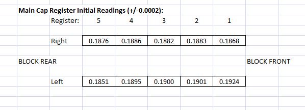


On average the left side of the block looked just a couple thousandths higher than the right side of the block, which I thought was pretty good given that the block was sitting upside down, and relying on the squareness of the end rails relative to the main cap registers.  In order to make the main cap registers as level as possible, I used some .004" shim stock under the right side of the block's end rails on each end.  I remeasured and got the following results:
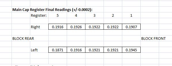


This brought the height of the #2 and #3 main cap registers just about the same, and #4 was only off by a thousandth.  #5 was off by almost 0.005", but that wasn't a concern because the girdle doesn't tie into the  #5 main cap.  The left side of #1 was about 0.004" higher than the right side, and I figured I could compensate for that with the spacers.

Now that the main registers were as squared up as I could make them, I measured the height of the oil pan rail in the four corners of the block:
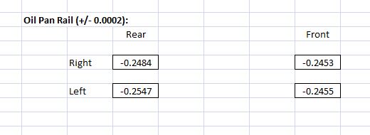


These results were not nearly as bad as I had been led to believe; worst case variation was only about 0.010", and since the distances across the block were much greater than the distances across the main cap registers, it really wasn't that bad.  Nevertheless, I set up my 3" facing mill and took about 0.012" off the oil pan rail, to square it up with the main cap registers:
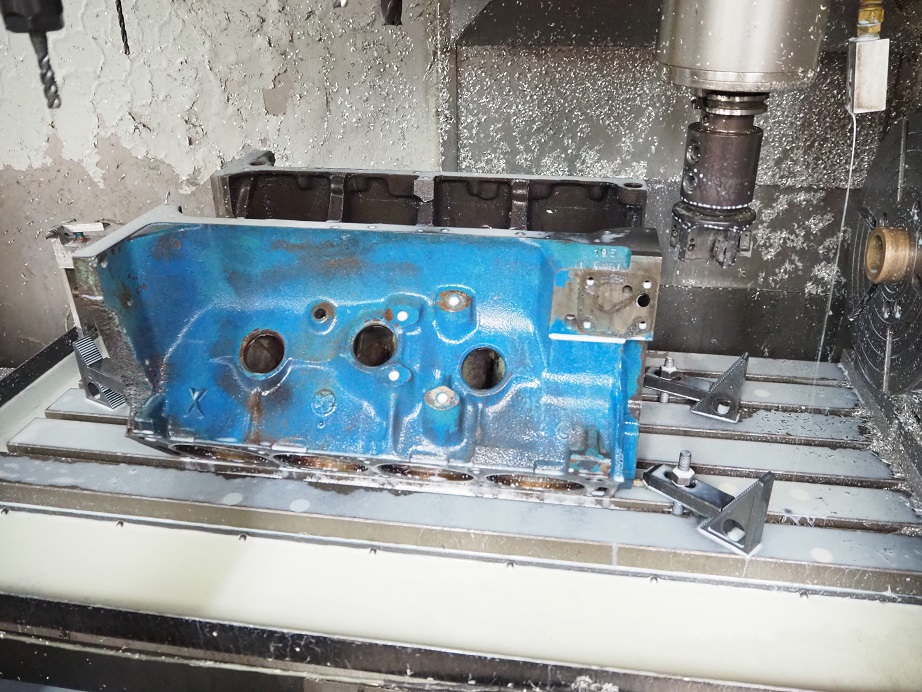


This whole process, from getting the block fixtured on the CNC machine, to cutting the pain rail, took about an hour and half.  No big deal.

Next I took caps 1 through 4 and put them into the vise on my smaller CNC machine.  I indicated off the ways of the vise in the Z axis, and then indicated on each main cap bolt hole to find it's center.  Then I wrote a short CNC program to spot face the bolt holes in the top of the caps, to make them all exactly the same height.  I tried to go to a 2.5" height from the bottom of the caps up to the spot face, but it turned out that one of the caps was a little lower than that, so I went down to a height of 2.475" to get all the spot faces on the caps exactly the same height from the bottom of the caps.  It took about an hour to machine the caps.

Another quick aside is that the manufacturer provides a spacer between the cap and the girdle that is a single piece strap for each cap, with two holes in it.  They tell you to bolt the girdle on the block, then measure the distance from the main cap registers up to the girdle, subtract the thickness of the strap, and machine the whole top of the cap to get the height to that dimension.  I also did not like this idea, it seemed to me that getting a precise measurement of this distance would be problematic, and also machining any more off the cap than necessary would limit the strength of the cap.  So I elected not to use the straps, and decided to make up some donut spacers instead.

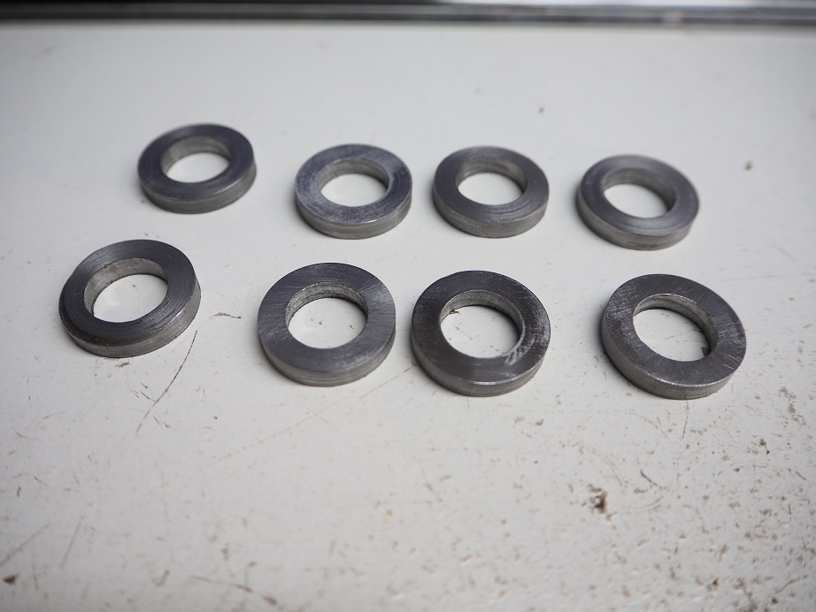
With the block still fixtured on the CNC machine, I measured the distance between the main cap registers and the oil pan rail, subtracted the 2.475" distance from the cap base to the spot face, and found that I needed spacers about 0.182" thick.  Due to slight variations in the height of the registers, I ended up machining spacers of slightly different thicknesses, ranging from 0.180" to 0.184".  This was the most time consuming part of the project, and hindsight being 20/20, I can think of a much easier way to do this; more on that shortly.  It took me about 3 hours to get these 8 donut spacers machined:


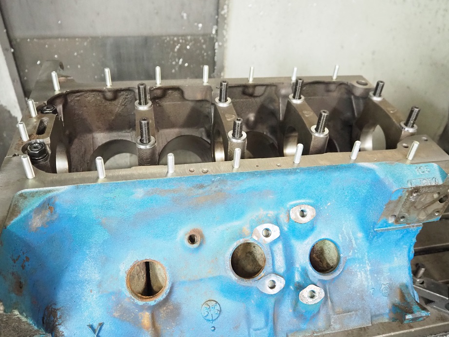
From there I assembled the main studs in the block.  The stud kit included two studs that were shorter than the other eight, for use in the #5 cap, but actually they were still too long to be used, and even with the presence of the girdle they would stick up above the oil pan rail.  The instructions said they "may" need to be cut to fit  ::)  Anyway, I had known about this issue and had the block owner buy some special, shorter studs for the #5 cap.  To make the stud washers and nuts fit, I also counterbored the #5 cap 0.275".  I installed the studs, the caps, and the spacers in the correct location to make them all the same height, then finally I installed the oil pan studs that came with the kit; here's a picture of how the block looked at this point:


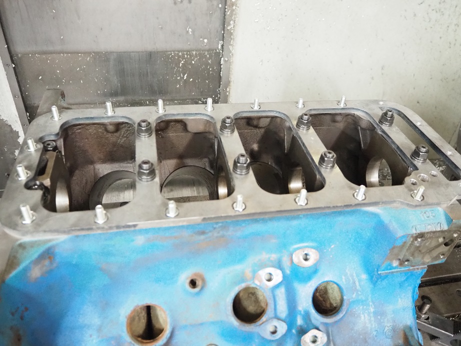
The girdle fit nicely down on the block, and in fact it could be wiggled around a little; probably the holes for the studs are slightly oversize.  The main stud washers and nuts were installed next.  The kit comes with some thin nuts that fit into the counterbored areas of the girdle.  I found that the counterbored holes were too small for my 3/8 drive 1/2" socket to fit, so I couldn't use that to tighten the nuts; I ended up going to a 1/4 drive ratchet and socket to get them tight. 


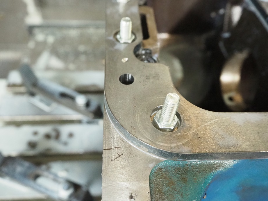
The last thing I did was to machine a couple of precision holes for some 3/8" diameter steel pins, in order to positively fixture the girdle on the pain rail.  I was uncomfortable with the fact that the girdle could slide around some when it was placed over the studs, and despite being clamped down, I wanted a more positive location for it.  So I machined two holes through the girdle and into the block, and will install some steel pins to lock it into a fixed position.  Here's a photo of one of the holes:


Having installed one of these now, I can say by comparison it is a much easier installation than the cross bolted caps.  With the crossbolted caps, the block has to be perfectly aligned in the X axis of the mill, and also perfectly machined to make the caps fit properly.  Then, the block has to be set up on the machine rotated 90 degrees along the X axis to drill the holes for the cross bolts on one side, then it has to be set up at -90 degrees to drill the crossbolt holes on the other side.  This is a ton of setup work, and horsing the block around to these different positions, and then fixturing it in those positions, is very time consuming.  Not to mention tapping the cross bolt holes in the caps.

Despite being more expensive by around $200, and requiring much more expensive machine work, the cross bolted caps are probably more rigid than the standard caps using a girdle.  My take on this though is that given the cylinder wall and main web thickness of a 390, the cross bolted caps may be overkill.  I'm pretty sure that the girdle will make the block able to withstand 650-700 HP, and it probably wouldn't be a good idea to go beyond that with a 390 block anyway.

One issue with the girdle that I don't like is that the spacers have to be kept in the same position, in order to maintain minimum stress on the girdle.  Since they are slightly different thicknesses, if you mix them up you may impart a twist into the girdle when it is assembled.  I thought I was going to be able to address this by just stamping or scribing each spacer with it's position, but that didn't turn out to be practical; the steel was not easy to scribe, and when I tested stamping an extra spacer, it raised the material around the stamp mark and changed the thickness.  So the spacers need to be carefully marked when removed, and then replaced in the same spot.

Another concern with the girdle is that if you want to run a windage tray, it is going to be spaced 3/8" farther from the crank, making it a little less effective.

Speaking of the spacers, if I was going to do this project again, I'd take advantage of the precise ring shims available from McMaster Carr.  For example, they have a 0.188" thick spacer with a thickness tolerance of +/- 0.007", and they have .001" and .002" thick ring spacers, with thickness tolerances of much less than .001".  Having a selection of those on hand, and cutting the main cap spot faces just a little deeper than I did, would allow these off the shelf shims to be used as the spacers, taking the majority of time out of this project.  If I ever do another one of these, that's what I'll do.

One last comment is that after this work is done, the block should be align honed, if it hasn't been already.  Sometimes the machine shop will take a few thousandths off the bottom of the caps to align hone the main saddle.  If that happens, then some of those really small shims mentioned previously will have to be added to the shims that are already in place between the girdle and the caps.  For example, if the shop takes .002" off the bottom of each cap, then a 0.002" shim should be installed with each spacer.  But again, since those shims are readily available, no big deal.

I hope this quick tutorial will help if you are considering a girdle for your engine.  Anybody with a vertical mill can do this work, although it is a little easier with CNC, and it seems like a good upgrade for a 390 or 428 block that is headed for serious horsepower.
« Last Edit: July 23, 2021, 03:39:27 PM by jayb »
Jay Brown
- 1969 Mach 1, Drag Week 2005 Winner NA/BB, 511" FE (10.60s @ 129); Drag Week 2007 Runner-Up PA/BB, 490" Supercharged FE (9.35 @ 151)
- 1964 Ford Galaxie, Drag Week 2009 Winner Modified NA (9.50s @ 143), 585" SOHC
- 1969 Shelby Clone, Drag Week 2015 Winner Modified NA (Average 8.98 @ 149), 585" SOHC


WConley

  • Hero Member
  • *****
  • Posts: 1163
  • No longer walking funny!
    • View Profile
Re: Installing an FE main stud girdle
« Reply #1 on: July 23, 2021, 04:37:54 PM »
You definitely went the extra mile on that installation.  Next time I have a block that needs free work, I'll keep you in mind  ;D

Question - How much torque were you able to get on those cap nuts with that little 1/4" drive setup?  You can get thin wall sockets for this purpose, or you can get ugly and grind a spare one down.

- Bill
A careful study of failure will yield the ingredients for success.

Thumperbird

  • Sr. Member
  • ****
  • Posts: 277
    • View Profile
Re: Installing an FE main stud girdle
« Reply #2 on: July 23, 2021, 08:26:39 PM »
Just spitballing here for fun, without a quality FEA really hard to know whats what.  Not criticizing your work AT ALL here Jay.

I wonder if things would be more rigid if pinned on both sides at each cap?
Don't care how tight fasteners are thermal expansion is a mighty beast to slay much less all the dynamic loading.
Wonder if a knurl of sorts for a surface finish on mating surfaces would truly make it behave more like one piece of material once clamped?  Or maybe one wants the plate to slide a bit due to thermals so it does not distort?

I've heard the blocks split between the cam and main bearings, where do we feel the weakest cross sections are contributing to instability and failure? The failure point is down the middle but what is giving up?  Or is the girdlefor some other failure mode?

Like I said, just peanut gallery thoughts.

jayb

  • Administrator
  • Hero Member
  • *****
  • Posts: 7407
    • View Profile
    • FE Power
Re: Installing an FE main stud girdle
« Reply #3 on: July 23, 2021, 09:02:07 PM »
You definitely went the extra mile on that installation.  Next time I have a block that needs free work, I'll keep you in mind  ;D

Question - How much torque were you able to get on those cap nuts with that little 1/4" drive setup?  You can get thin wall sockets for this purpose, or you can get ugly and grind a spare one down.

- Bill

Man, I shouldn't have said anything about free block work LOL!  I didn't torque those nuts to a specific spec Bill, just tightened them kind of like you would with a pan bolt.  The girdle is going to have to come off anyway at some point if the block is aligned honed, so I didn't bother with a complete torquing sequence.
Jay Brown
- 1969 Mach 1, Drag Week 2005 Winner NA/BB, 511" FE (10.60s @ 129); Drag Week 2007 Runner-Up PA/BB, 490" Supercharged FE (9.35 @ 151)
- 1964 Ford Galaxie, Drag Week 2009 Winner Modified NA (9.50s @ 143), 585" SOHC
- 1969 Shelby Clone, Drag Week 2015 Winner Modified NA (Average 8.98 @ 149), 585" SOHC


jayb

  • Administrator
  • Hero Member
  • *****
  • Posts: 7407
    • View Profile
    • FE Power
Re: Installing an FE main stud girdle
« Reply #4 on: July 23, 2021, 09:29:52 PM »
Just spitballing here for fun, without a quality FEA really hard to know whats what.  Not criticizing your work AT ALL here Jay.

I wonder if things would be more rigid if pinned on both sides at each cap?
Don't care how tight fasteners are thermal expansion is a mighty beast to slay much less all the dynamic loading.
Wonder if a knurl of sorts for a surface finish on mating surfaces would truly make it behave more like one piece of material once clamped?  Or maybe one wants the plate to slide a bit due to thermals so it does not distort?

I've heard the blocks split between the cam and main bearings, where do we feel the weakest cross sections are contributing to instability and failure? The failure point is down the middle but what is giving up?  Or is the girdlefor some other failure mode?

Like I said, just peanut gallery thoughts.

I was actually going to do what you are suggesting, because I think more of those pins would be better.  The problem is that the thickness of the block casting at the pan rail, across from the main caps, isn't great; not a lot of meat there.  I wanted to put the pins into some locations that were really rigid, so going to the ends of the block looked like the best solution to me.

As I understand the failure mechanism of a two bolt FE block, the #2 and #4 caps will twist a little, in high load situations, eventually causing a crack along the oil hole that runs from the main saddle to the cam bearing bores.  I think the girdle is well positioned to resist that kind of movement and prevent the cracks, provided that the torque on the main studs is strong enough to keep the whole "sandwich" of the girdle, spacers, caps, and block together.  If you weren't confident of that, one thing that could be done is to put a 1/4" steel pin down through the girdle, the spacer, and the cap, right next to each main cap bolt hole.  You could also pin the caps to the block, at the registers.  But these modifications would be time consuming and expensive, and would also probably weaken the whole assembly somewhat.  I think the 110 foot pounds of torque on those studs is strong enough to keep the assembly rigid.

By the way, the blocks that usually split in half are factory 289 and 302 small blocks; there are numerous examples of those blocks breaking in half right along the main web if pushed much higher than 500 HP.  I've never seen, or heard of, an FE block that has actually split totally in half, but cracks along the #2 and #4 main saddle are relatively common.

One last comment is that a couple of my customers, one of whom is a road racer in New Zealand, have told me that they cannot keep a 390 block together for a season of racing unless they install a girdle.  So I think the idea of a girdle to stabilize the main web is pretty well proven; it is the implementation that can be a problem. 
Jay Brown
- 1969 Mach 1, Drag Week 2005 Winner NA/BB, 511" FE (10.60s @ 129); Drag Week 2007 Runner-Up PA/BB, 490" Supercharged FE (9.35 @ 151)
- 1964 Ford Galaxie, Drag Week 2009 Winner Modified NA (9.50s @ 143), 585" SOHC
- 1969 Shelby Clone, Drag Week 2015 Winner Modified NA (Average 8.98 @ 149), 585" SOHC


cammerfe

  • Hero Member
  • *****
  • Posts: 1660
    • View Profile
Re: Installing an FE main stud girdle
« Reply #5 on: July 23, 2021, 10:28:09 PM »
As usual, you tread where no man has gone ---and then talked about it. Most sincere thanks for all your efforts.

KS

winr1

  • Guest
Re: Installing an FE main stud girdle
« Reply #6 on: July 23, 2021, 10:49:12 PM »
Thanks Jay !!


Ricky.

428 GALAXIE

  • Full Member
  • ***
  • Posts: 158
    • View Profile
Re: Installing an FE main stud girdle
« Reply #7 on: July 24, 2021, 01:23:45 AM »
What if that girdle would be say inch and A half thick.
Mill A pocket for oil pump breathing/oil/pipe holes beetween caps,plate and sump to keep oil inside or just plate if dry sump.
Definently not worth if you pay for the labor but if you have A mill and sparetime (and couple of turbos to split the cylinder walls;))
Mikko

Barry_R

  • Hero Member
  • *****
  • Posts: 1918
    • View Profile
    • Survival Motorsports
Re: Installing an FE main stud girdle
« Reply #8 on: July 24, 2021, 06:36:03 AM »
That is pretty much the process we use to install a girdle here the few times we have done it.  Your block is/was better than some we have seen.

Seems like it takes us about the same time as installing cross bolt caps.  If you are more concerned with functionality than cosmetics with cross bolt installation, you can slide the mill across the inside and the outside of the pan rail leaving a straight and constant thickness flat surface on both side of the rail.  Then the lateral cross bolt holes can be drilled manually with a simple fixture if you don't want to rotate the block back and forth.

Back to girdle installation - we mill and spot face the caps after installing them to try and get the needed spacers to the same thickness if possible.  Simplifies engine assembly and future service.

Since you are clamp loading the girdle with the mains you really do need to have the whole enchilada as near to flat as possible - we see a half thou clearance change on 427 block just by torquing the cross bolts - and those are set to near zero fit between the spacers and the caps.  And installion process and location needs to be repeatable in service.

You can add dowels to the pan rails at any place even if rather thin.  They are assembly location devices and should not see lateral loads once installed.

Problem I have with girdles is that - by the time you buy one and have a shop install it at retail prices for the average guy - you are approaching half the cost of an aftermarket 427 block.  That kinda negates the reason for starting with a 390 in the first place since the 427 is a far better product by every measurement.  If you have a mill and the ability to do the installation your self that comment does not apply.  Just be aware that the girdle is not a "pull it out of the box and bolt it on" deal as some information might have folks believe.

Time for me to get back to moving stuff - - relocating the shop....

blykins

  • Hero Member
  • *****
  • Posts: 4828
    • View Profile
    • Lykins Motorsports
Re: Installing an FE main stud girdle
« Reply #9 on: July 24, 2021, 07:07:36 AM »
You can really get into a tail-chasing scenario with them.  The block really needs to be align honed before hand so that the cap mating surfaces would be "prepped" before you start to machine the tops of the caps and fit the girdle, then you need to align hone the entire assembly once installed (or at least bore gauge the mains again) so that there are no chances that the clamping of the girdle affects the main bore alignment.  Pinning the girdle is a good idea and would probably help some there so that there is no guesswork on pulling the girdle on and off. 

I agree with Barry that I think you got a "good" block.  I've seen some really whopper-jawed factory machine work come through here.  Deck surfaces off .020" from front to back, etc. 

Combining all of this with the fact that you have a mating surface that's not gasketed, having to potentially port match the oil pump hole in the girdle, run a longer pump drive, having the pan moved down away from the block the thickness of the girdle, etc., I'm just not a big fan of them.  I'd much rather see cross bolted caps (even if just on #2 and #4 only).   I'm not even a fan of oil pan studs simply because the oil pan manufacturers can't get their junk together enough to put all the holes in the pan rails in the same spots every time.  That's another soap box for another time.

Brent Lykins
Lykins Motorsports
Custom FE Street, Drag Race, Road Race, and Pulling Truck Engines
Custom Roller & Flat Tappet Camshafts
www.lykinsmotorsports.com
brent@lykinsmotorsports.com
www.customfordcams.com
502-759-1431
Instagram:  brentlykinsmotorsports
YouTube:  Lykins Motorsports

BruceS

  • Hero Member
  • *****
  • Posts: 738
    • View Profile
Re: Installing an FE main stud girdle
« Reply #10 on: July 24, 2021, 08:17:29 AM »
Jay, as for marking spacers have you tried a vibrating hand-held engraver?  Seems like you could mark the spacers on the sides for girdle or crossbolts without distorting them. 
66 Fairlane 500, 347-4V SB stroker, C4
63 Galaxie 500 fastback, 482 SO 4V, Cruise-O-Matic

jayb

  • Administrator
  • Hero Member
  • *****
  • Posts: 7407
    • View Profile
    • FE Power
Re: Installing an FE main stud girdle
« Reply #11 on: July 24, 2021, 09:17:02 AM »
That is pretty much the process we use to install a girdle here the few times we have done it.  Your block is/was better than some we have seen.

Seems like it takes us about the same time as installing cross bolt caps.  If you are more concerned with functionality than cosmetics with cross bolt installation, you can slide the mill across the inside and the outside of the pan rail leaving a straight and constant thickness flat surface on both side of the rail.  Then the lateral cross bolt holes can be drilled manually with a simple fixture if you don't want to rotate the block back and forth.

Back to girdle installation - we mill and spot face the caps after installing them to try and get the needed spacers to the same thickness if possible.  Simplifies engine assembly and future service.

Since you are clamp loading the girdle with the mains you really do need to have the whole enchilada as near to flat as possible - we see a half thou clearance change on 427 block just by torquing the cross bolts - and those are set to near zero fit between the spacers and the caps.  And installion process and location needs to be repeatable in service.

You can add dowels to the pan rails at any place even if rather thin.  They are assembly location devices and should not see lateral loads once installed.

Problem I have with girdles is that - by the time you buy one and have a shop install it at retail prices for the average guy - you are approaching half the cost of an aftermarket 427 block.  That kinda negates the reason for starting with a 390 in the first place since the 427 is a far better product by every measurement.  If you have a mill and the ability to do the installation your self that comment does not apply.  Just be aware that the girdle is not a "pull it out of the box and bolt it on" deal as some information might have folks believe.

Time for me to get back to moving stuff - - relocating the shop....

Barry, thanks for the comments.  It's interesting that you and Brent both say that this was a good block to start with.  I'm surprised by that; I kind of figured that indicating off the main registers on any block would show them all to be pretty close to flat.  I've got to believe that the main registers are all machined in one pass at the factory; how could they be way off?  Maybe running for 100,000+ miles in the car or truck warps or twists the block?  The oil pan rail being off kilter from the main registers makes sense, though...

I can see that if there was a fixture available to drill the crossbolt holes in the right location, and square to the side of the block, and if the fixture could also be used to spotface the holes, the difference between machining for the crossbolt caps and the girdle would be negligible.  I imagine you have constructed a fixture like that, and probably a few other engine builders have them, but most don't, so I think a guy taking his block in for crossbolt installation to his local shop would probably be stuck with paying a pretty high labor bill.  It took me over 10 hours to install the crossbolt caps on my engine, and at today's labor rates that would be around $1000.  It only took me half as long to do the girdle.

As far as the cost goes, I think that the aftermarket blocks start at around $3800, and they need the same align hone and block deck work that a factory block would need.  So, if you find a usable 390 block for $300, buy the girdle for $450, and then spend $500 to get it installed, you are only about a third the cost of an aftermarket block.  Seems like saving $2500, or even $2000, on the engine build would be a strong motivator for a lot of guys.

Also on the dowel pins, I actually was concerned that the girdle might see lateral loads.  It really shouldn't, but I've seen plenty of unusual failures over the years, so in case it did want to move I wanted a positive alignment mechanism, not just those oil pan studs clamping it to the block.  Maybe not necessary, but you never know...
Jay Brown
- 1969 Mach 1, Drag Week 2005 Winner NA/BB, 511" FE (10.60s @ 129); Drag Week 2007 Runner-Up PA/BB, 490" Supercharged FE (9.35 @ 151)
- 1964 Ford Galaxie, Drag Week 2009 Winner Modified NA (9.50s @ 143), 585" SOHC
- 1969 Shelby Clone, Drag Week 2015 Winner Modified NA (Average 8.98 @ 149), 585" SOHC


jayb

  • Administrator
  • Hero Member
  • *****
  • Posts: 7407
    • View Profile
    • FE Power
Re: Installing an FE main stud girdle
« Reply #12 on: July 24, 2021, 09:18:09 AM »
Jay, as for marking spacers have you tried a vibrating hand-held engraver?  Seems like you could mark the spacers on the sides for girdle or crossbolts without distorting them.

I don't have one of those and have never used one, but if that is the same tool that is used to mark the factory 427 crossbolt spacers, then it would probably work.
Jay Brown
- 1969 Mach 1, Drag Week 2005 Winner NA/BB, 511" FE (10.60s @ 129); Drag Week 2007 Runner-Up PA/BB, 490" Supercharged FE (9.35 @ 151)
- 1964 Ford Galaxie, Drag Week 2009 Winner Modified NA (9.50s @ 143), 585" SOHC
- 1969 Shelby Clone, Drag Week 2015 Winner Modified NA (Average 8.98 @ 149), 585" SOHC


427mach1

  • Full Member
  • ***
  • Posts: 120
    • View Profile
Re: Installing an FE main stud girdle
« Reply #13 on: July 24, 2021, 10:10:50 AM »
Jay, as for marking spacers have you tried a vibrating hand-held engraver?  Seems like you could mark the spacers on the sides for girdle or crossbolts without distorting them.

I don't have one of those and have never used one, but if that is the same tool that is used to mark the factory 427 crossbolt spacers, then it would probably work.

I believe that is the tool used to mark the cross-bolt spacers.  The first time I took my 427 apart, I didn't know the spacers were fitted to each location.  Fortunately, when it went back together, we found the markings.

Gaugster

  • Sr. Member
  • ****
  • Posts: 396
    • View Profile
Re: Installing an FE main stud girdle
« Reply #14 on: July 24, 2021, 10:17:49 AM »
Well - I'm the guy that cannonballed up to Jay's place. Just couldn't pass up the offer for some free machine work and had time to hunt down a girdle. I wasn't going to mention the "free" part but it's out there now. Thanks again Jay for the work and also the tour of your work shop. Very impressive and was nice to meet you!

The block is my D3TE MCC "105" block and good to here that it's measuring in decent shape. Girdle kit is from Concept Design Engineer LLC. I.e. Tim on Ebay but purchased secondhand. I will be documenting the main bores and putting my straight edge to use but went down this path assuming a line hone and additional shims will be needed. Cost, Reliability, Value etc. are factors for me like most people. Finding that balance is always a struggle but so far I have met and done business with lots of good folks in the FE community.
John - '68 Cougar XR7 390 FE (X-Code) 6R80 AUTO

Gaugster

  • Sr. Member
  • ****
  • Posts: 396
    • View Profile
Re: Installing an FE main stud girdle
« Reply #15 on: July 24, 2021, 10:31:12 AM »
What if that girdle would be say inch and A half thick.
Mill A pocket for oil pump breathing/oil/pipe holes beetween caps,plate and sump to keep oil inside or just plate if dry sump.
Definently not worth if you pay for the labor but if you have A mill and sparetime (and couple of turbos to split the cylinder walls;))
The kit comes with an extended oil pump shaft to make up for the thickness of the girdle. A thicker design would need hardware to complement. Here's an article I found while considering the girdle option. It talks about 1.5 to 2" thick options. I don't know anything good or bad about Hughes Engines but ya know those Mopar guys are crazy.  ;D

http://www.hughesengines.com/TechArticles/2mainbearingstudgirdles04232007.php
John - '68 Cougar XR7 390 FE (X-Code) 6R80 AUTO

jayb

  • Administrator
  • Hero Member
  • *****
  • Posts: 7407
    • View Profile
    • FE Power
Re: Installing an FE main stud girdle
« Reply #16 on: July 24, 2021, 10:44:32 AM »
John, I really wanted to do one of these to see what was involved, so thanks to you for bringing it up so I could install it - Jay
Jay Brown
- 1969 Mach 1, Drag Week 2005 Winner NA/BB, 511" FE (10.60s @ 129); Drag Week 2007 Runner-Up PA/BB, 490" Supercharged FE (9.35 @ 151)
- 1964 Ford Galaxie, Drag Week 2009 Winner Modified NA (9.50s @ 143), 585" SOHC
- 1969 Shelby Clone, Drag Week 2015 Winner Modified NA (Average 8.98 @ 149), 585" SOHC


MeanGene

  • Sr. Member
  • ****
  • Posts: 450
    • View Profile
Re: Installing an FE main stud girdle
« Reply #17 on: July 24, 2021, 11:04:00 AM »
I got one of the first kits from Tim, about 10 yrs ago- to be fair, he is a good machinist, but not an engine shop guy, and made one for a buddy when asked, so that's why the install directions are a bit iffy. I had the help of a very good engine guy who is a whiz on the mill, and had to feel our way through it as Jay did. It came with washers to sit on the caps, and no mention of fitting or trimming the pan rail or washers in the "directions". Someone suggested the straps to him, so he sent me a set, and I also did not like the idea of flat-cutting the caps as it would weaken them, so the washers were fitted. Everything else went as in Jay's install, except one thing my pea brain dreamed up, that after trimming the pan rails, it left the timing cover hanging down a bit below the rails. I always try to install the covers by letting them self-center on the seal and then snug up, so the misalignment might cause a leak with the stock gasket, plus if one took the cover off later for a cam change or whatever, the cover would not seat correctly, but be pressured up and put the seal out of alignment. I set it up on the BP and took a .030 cut off the area that met the cover, instead of cutting the cover, so any cover could be used. Installed the cover as usual, which left a small gap to the girdle. Installed the girdle with some RTV, and a bigger bead where the cover sits, fit great.

pbf777

  • Sr. Member
  • ****
  • Posts: 491
    • View Profile
Re: Installing an FE main stud girdle
« Reply #18 on: July 24, 2021, 11:15:43 AM »
The block really needs to be align honed before hand so that the cap mating surfaces would be "prepped" before you start to machine the tops of the caps and fit the girdle, then you need to align hone the entire assembly once installed (or at least bore gauge the mains again) so that there are no chances that the clamping of the girdle affects the main bore alignment. 


     In our experience installing these girdles, they will influence the bore roundness not so much alignment (if things were squared properly), so we always align-hone the block less the girdle to a point in the process of believing that no additional cutting of the caps will be necessary, stop short of final size, finish all machining for fitment of the girdle, install and torque to spec., then finish the final to bore size honing.  Skipping this process will most often leave one with out-of-round bores!     ;)

     And yes, your example block was a 'good-one', as they have proven in our experience in the past to often demonstrate quite greater deviations in measurement, as I find it necessary to re-machine the block to cap register surfaces to level as well, and with this I end with all equal dimension from that position onward (no select fit shimming    8)  ), and also if you check the left/right registers you'll find them also not in alignment at times.     :)

     Scott. 


WConley

  • Hero Member
  • *****
  • Posts: 1163
  • No longer walking funny!
    • View Profile
Re: Installing an FE main stud girdle
« Reply #19 on: July 24, 2021, 12:06:24 PM »

... I kind of figured that indicating off the main registers on any block would show them all to be pretty close to flat.  I've got to believe that the main registers are all machined in one pass at the factory; how could they be way off?  Maybe running for 100,000+ miles in the car or truck warps or twists the block?  ...


Yeah, the saddles were machined together in one big broaching pass.  The problem is that the block material was still green.  100K miles of thermal cycles and load will tend to move the material around a bit as internal stresses relieve.
A careful study of failure will yield the ingredients for success.

My427stang

  • Hero Member
  • *****
  • Posts: 3941
    • View Profile
Re: Installing an FE main stud girdle
« Reply #20 on: July 24, 2021, 12:41:08 PM »
I don't have anything to back it up, but I think that anything you can do to dissipate whatever harmonics are happening on those two unsupported mains would help.

The majority of the #2 and #4 issues I see are with low rpm propane industrials, and they sure aren't overpowering the block!  #1 to a lesser extent and #5 are supported by some material around them, #3, even if it's not direct support has a thrust touching it, but the other two I think, could be cross bolted, girdled, pinned, if you could control expansion, even the goofy "wedge bolts" Gene was making fun of could "in theory....not in my shop" LOL help with potentially killing the harmonics at that main.

Right or wrong, they sure do break.  Standard practice for me is 1-spot check with sonic, 2-clean, 3-mag and pressure, 4 - then machine.  I will even pay extra if it comes with a "money back if #2 and #4 are cracked" guarantee
---------------------------------
Ross
Bullock's Power Service, LLC
- 70 Fastback Mustang, 489 cid FE, Victor, SEFI, Erson SFT cam, TKO-600 5 speed, 4.11 9 inch.
- 71 F100 shortbed 4x4, 461 cid FE, headers, Victor Pro-flo EFI, Comp Custom HFT cam, 3.50 9 inch

frnkeore

  • Hero Member
  • *****
  • Posts: 1140
    • View Profile
Re: Installing an FE main stud girdle
« Reply #21 on: July 24, 2021, 01:44:13 PM »
I've thought about installing a girdle on my industrial engine but, the girdle price ($450) stops me. I realize there isn't the same volume as SB's but, I always set limits on what I'll pay for something. So, I've thought about how I would install one.

I wasn't aware that the saddles were off that much. I didn't measure the saddle height when I had my Edsel on the mill. So, I think that I would start this, by paralleling the saddles at #1 & 5 and taking a clean up cut on the top of the china walls. That would give you the best average height to lean up the saddles.

I would diffidently use dowel pins in either 4 or 6 locations, inline with the center mains and I would use 3/8 Pull Dowels, to do that, they have a 10x32 thread so, you can take them back out. You would drill and ream the girdle 3/8, giving a .0002 press, in both the block and girdle, locating the girdle with 4 flathead bolts, to center it first. 

Regarding making all the c'bores the same, I would install the caps and then run a 1" sq bar across them (shimming if necessary) to hold them in place, then c'bore. Then come back a ream 5/8" x .32 dp. Then use the below doweling.

Finally, before honing, I would use 5/8 hollow dowels, for each bolt, from the girdle, into the caps. Only going into the cap ~5/16". Since the spacer thickness would be fixed, the dowel section could be integral with the spacer. Of course the trust would have to be aligned first. The hollow dowels could be a press fit into the girdle. set the girdle on the caps, work it down, install the 3/8 dowels and torque. You could also use hollow dowels at the bottom but, you'd have to do that first, after surfacing the register area.
Frank

70tp

  • Full Member
  • ***
  • Posts: 101
    • View Profile
Re: Installing an FE main stud girdle
« Reply #22 on: July 24, 2021, 04:57:47 PM »
What kind of sealer is commonly used between the girdle and block?   And does the sealer thickness , if any, affect the shim height?   Maybe an o ring groove would be an option, idk?

Gaugster

  • Sr. Member
  • ****
  • Posts: 396
    • View Profile
Re: Installing an FE main stud girdle
« Reply #23 on: July 24, 2021, 05:52:46 PM »
What kind of sealer is commonly used between the girdle and block?   And does the sealer thickness , if any, affect the shim height?   Maybe an o ring groove would be an option, idk?
Kit comes with Permatex. Presumably it will be compressed out of the mating surface and only take up any gaps.
John - '68 Cougar XR7 390 FE (X-Code) 6R80 AUTO

jayb

  • Administrator
  • Hero Member
  • *****
  • Posts: 7407
    • View Profile
    • FE Power
Re: Installing an FE main stud girdle
« Reply #24 on: July 25, 2021, 09:14:46 AM »
It might be possible to drill some little divots in the spacers, and then Permatex them to the girdle so that they wouldn't get mixed up.  JB Weld would be even better.  Just a thought...
Jay Brown
- 1969 Mach 1, Drag Week 2005 Winner NA/BB, 511" FE (10.60s @ 129); Drag Week 2007 Runner-Up PA/BB, 490" Supercharged FE (9.35 @ 151)
- 1964 Ford Galaxie, Drag Week 2009 Winner Modified NA (9.50s @ 143), 585" SOHC
- 1969 Shelby Clone, Drag Week 2015 Winner Modified NA (Average 8.98 @ 149), 585" SOHC


GerryP

  • Hero Member
  • *****
  • Posts: 569
    • View Profile
Re: Installing an FE main stud girdle
« Reply #25 on: July 25, 2021, 04:06:30 PM »
I think that junction would be the perfect application for hylomar.  It is made for sealing on metal-to-metal.

JERICOGTX

  • Sr. Member
  • ****
  • Posts: 336
    • View Profile
Re: Installing an FE main stud girdle
« Reply #26 on: July 26, 2021, 09:30:53 AM »
Jay, does anyone make aluminum main caps for a FE? On higher HP stock block Mopar's, it's best to use an aluminum main cap setup. The main webs are the weak link, and using aluminum, it acts as a cushion, and doesn't beat the main webs out of the block.

Gaugster

  • Sr. Member
  • ****
  • Posts: 396
    • View Profile
Re: Installing an FE main stud girdle
« Reply #27 on: July 26, 2021, 10:55:23 AM »
Personally I think I should be able to tag and bag the spacers in order to keep them organized. I'd wonder about where those bonding materials could migrate too if it was applied heavy and loosen up during use. Plenty of warnings out there on the internet about messed up oil pumps and bearing surfaces due to excessive gasket makers on oil pans, intakes etc...
John - '68 Cougar XR7 390 FE (X-Code) 6R80 AUTO

jayb

  • Administrator
  • Hero Member
  • *****
  • Posts: 7407
    • View Profile
    • FE Power
Re: Installing an FE main stud girdle
« Reply #28 on: July 26, 2021, 11:32:30 AM »
Jay, does anyone make aluminum main caps for a FE? On higher HP stock block Mopar's, it's best to use an aluminum main cap setup. The main webs are the weak link, and using aluminum, it acts as a cushion, and doesn't beat the main webs out of the block.

I don't know of anyone making aluminum main caps for the FE.  For a brief time, the Shelby aluminum blocks came with aluminum caps, but they quickly reverted to steel caps, I assume due to customer complaints. 

It's interesting that the big block Mopars seem to really like the aluminum caps, but that they are viewed as a negative in the FE world.  Maybe different failure mechanisms between the blocks, making aluminum caps work better on the Mopar blocks than on the FE?
Jay Brown
- 1969 Mach 1, Drag Week 2005 Winner NA/BB, 511" FE (10.60s @ 129); Drag Week 2007 Runner-Up PA/BB, 490" Supercharged FE (9.35 @ 151)
- 1964 Ford Galaxie, Drag Week 2009 Winner Modified NA (9.50s @ 143), 585" SOHC
- 1969 Shelby Clone, Drag Week 2015 Winner Modified NA (Average 8.98 @ 149), 585" SOHC


JERICOGTX

  • Sr. Member
  • ****
  • Posts: 336
    • View Profile
Re: Installing an FE main stud girdle
« Reply #29 on: July 27, 2021, 06:55:46 AM »
The aluminum caps are only used on iron blocks. My INDY block, which is aluminum, has billet steel caps. On a stock block, the aluminum dampens the shock the caps put on the main webs. Some people use billet steel caps, but those are thought of transferring MORE stress to the main webs.

Are the main webs a weak link in a stock block FE? If not, what is to be gained by a girdle for them?

jayb

  • Administrator
  • Hero Member
  • *****
  • Posts: 7407
    • View Profile
    • FE Power
Re: Installing an FE main stud girdle
« Reply #30 on: July 27, 2021, 08:20:35 AM »
My understanding is that the girdle prevents the cap from twisting under load.  Enough of that twisting will crack the block between the mains and the cam journals of #2 and #4, right along the oil passage between the two.  You don't see the main webs break, you just get that crack.  I don't think an aluminum cap would help in that case. 

I have to say though that I'm really not sure if that is the failure mechanism.  However, the girdle does seem to strengthen the block, at least according to several of my customers who have used them.  Jeff, girdles are also available for big block Mopars, are they not commonly used?
Jay Brown
- 1969 Mach 1, Drag Week 2005 Winner NA/BB, 511" FE (10.60s @ 129); Drag Week 2007 Runner-Up PA/BB, 490" Supercharged FE (9.35 @ 151)
- 1964 Ford Galaxie, Drag Week 2009 Winner Modified NA (9.50s @ 143), 585" SOHC
- 1969 Shelby Clone, Drag Week 2015 Winner Modified NA (Average 8.98 @ 149), 585" SOHC


Dumpling

  • Sr. Member
  • ****
  • Posts: 394
    • View Profile
Re: Installing an FE main stud girdle
« Reply #31 on: July 27, 2021, 10:17:00 AM »
Would there be a reason to install a girdle on a cross-bolted block?
Is one support mechanism better?

blykins

  • Hero Member
  • *****
  • Posts: 4828
    • View Profile
    • Lykins Motorsports
Re: Installing an FE main stud girdle
« Reply #32 on: July 27, 2021, 12:44:12 PM »
Would there be a reason to install a girdle on a cross-bolted block?
Is one support mechanism better?

In my mind the cross-bolted block is stronger.  The cap is preloaded in two directions. 

All of your aftermarket blocks have cross-bolted mains.  Non-skirted aftermarket blocks use 4-bolt/splayed caps.  You will never see an aftermarket block designed with a girdle.
« Last Edit: July 27, 2021, 12:48:05 PM by blykins »
Brent Lykins
Lykins Motorsports
Custom FE Street, Drag Race, Road Race, and Pulling Truck Engines
Custom Roller & Flat Tappet Camshafts
www.lykinsmotorsports.com
brent@lykinsmotorsports.com
www.customfordcams.com
502-759-1431
Instagram:  brentlykinsmotorsports
YouTube:  Lykins Motorsports

67xr7cat

  • Sr. Member
  • ****
  • Posts: 315
    • View Profile
Re: Installing an FE main stud girdle
« Reply #33 on: July 27, 2021, 09:18:07 PM »
Would there be a reason to install a girdle on a cross-bolted block?
Is one support mechanism better?

Think normally you either do the girdle or the cross bolted main caps. I'd think strength wise the order would be stock, then girdle, then block with cross bolted billet caps, then make the jump to an aftermarket block.   

I had an old article from 1967 about a top fuel racer who was running the 427 SOHC on nitromethane and was using the factory 427 cross bolted block and a home made girdle too to keep the crank off  the pavement. Said he had a lot of failed blocks.  Man, wish I could find that article again or remember the guys name!

Gaugster

  • Sr. Member
  • ****
  • Posts: 396
    • View Profile
Re: Installing an FE main stud girdle
« Reply #34 on: July 27, 2021, 09:30:03 PM »
Would there be a reason to install a girdle on a cross-bolted block?
Is one support mechanism better?

Think normally you either do the girdle or the cross bolted main caps. I'd think strength wise the order would be stock, then girdle, then block with cross bolted billet caps, then make the jump to an aftermarket block.   

I had an old article from 1967 about a top fuel racer who was running the 427 SOHC on nitromethane and was using the factory 427 cross bolted block and a home made girdle too to keep the crank off  the pavement. Said he had a lot of failed blocks.  Man, wish I could find that article again or remember the guys name!
Mickey Thompson?  ;D
John - '68 Cougar XR7 390 FE (X-Code) 6R80 AUTO

67xr7cat

  • Sr. Member
  • ****
  • Posts: 315
    • View Profile
Re: Installing an FE main stud girdle
« Reply #35 on: July 27, 2021, 10:34:45 PM »
Was Ed Pink

Found the article:

http://wildaboutcarsonline.com/members/AardvarkPublisherAttachments/9990392503331/1969-05_CC_SOHC_Magical_Mystery_Tour_1-10.pdf

Was actually post up on this forum in this thread:

http://fepower.net/simplemachinesforum/index.php?topic=4970.0

Is interesting what they did to those Nitro Cammer engines.  The girdle install is a bit different too! Guess is appropriate to this thread!

67xr7cat

  • Sr. Member
  • ****
  • Posts: 315
    • View Profile
Re: Installing an FE main stud girdle
« Reply #36 on: July 27, 2021, 10:45:00 PM »
My understanding is that the girdle prevents the cap from twisting under load.  Enough of that twisting will crack the block between the mains and the cam journals of #2 and #4, right along the oil passage between the two.  You don't see the main webs break, you just get that crack.  I don't think an aluminum cap would help in that case. 

I have to say though that I'm really not sure if that is the failure mechanism.  However, the girdle does seem to strengthen the block, at least according to several of my customers who have used them.  Jeff, girdles are also available for big block Mopars, are they not commonly used?

Is it twisting or caps deflecting inwards are the crank tries to be forced out the bottom?  I've always thought was cap defection pushing the bolts sideways.  The oil hole makes for the ideal weak spot plus lack of support with that big cam journal hole.  Guess if you milled the caps flat and put a 1" piece of bar stock across them be an interesting experiment to see if it stops the block from cracking at the oil holes. Without a doubt the girdle or crossed bolted mains help stabilize the caps too.

Joey120373

  • Sr. Member
  • ****
  • Posts: 372
    • View Profile
Re: Installing an FE main stud girdle
« Reply #37 on: July 28, 2021, 05:24:57 PM »
So here’s a thought that’s been rolling around in my head for ages.
The factory caps had individual spacers that were hand picked for the positions they fit.

The aftermarket caps have built in spacers, requiring precise machining to the block to get the right fit.

Would a cap that was built with an adjustable, threaded spacer , be an easier solution? Basically, for instance,  the cap would have a protrusion either side with a large diameter female thread, the “spacer”
Would essentially be a hollow bolt that could be screwed out to interface with the block. Then the actual cross bolt would thread into the cap through the center of all that. That way, from a machining standpoint, the only critical thing would be ensuring that the pan rails were machined square to the cap centerline so that they didn’t impart and twist.

I realize that there would be slip or play in the outer threaded portion, however, once it’s all torqued down that might not be a problem. This would also allow a certain ammout of pre loading to the block, like the old 1.5l turbo Indy car motors used. Since it’s the fore and aft movement of the cap that is what we want to control (correct?) would such an arrangement work for that?

Kinda just thinking out loud, but like I said it’s a thought I’ve had for years, logic tells me that if that was a viable solution, someone would have done it already…

Joe

blykins

  • Hero Member
  • *****
  • Posts: 4828
    • View Profile
    • Lykins Motorsports
Re: Installing an FE main stud girdle
« Reply #38 on: July 28, 2021, 05:59:55 PM »
It’s a valid design.  Ford 4.6L blocks are designed like that.  They have jack bolts between the cap and block.  You screw them out until they touch, then torque them to spec, which preloads the system. 
Brent Lykins
Lykins Motorsports
Custom FE Street, Drag Race, Road Race, and Pulling Truck Engines
Custom Roller & Flat Tappet Camshafts
www.lykinsmotorsports.com
brent@lykinsmotorsports.com
www.customfordcams.com
502-759-1431
Instagram:  brentlykinsmotorsports
YouTube:  Lykins Motorsports

My427stang

  • Hero Member
  • *****
  • Posts: 3941
    • View Profile
Re: Installing an FE main stud girdle
« Reply #39 on: July 28, 2021, 07:07:32 PM »
My understanding is that the girdle prevents the cap from twisting under load.  Enough of that twisting will crack the block between the mains and the cam journals of #2 and #4, right along the oil passage between the two.  You don't see the main webs break, you just get that crack.  I don't think an aluminum cap would help in that case. 

I have to say though that I'm really not sure if that is the failure mechanism.  However, the girdle does seem to strengthen the block, at least according to several of my customers who have used them.  Jeff, girdles are also available for big block Mopars, are they not commonly used?

I haven't wrapped my head around the cause either.  Certainly there is no twisting caused by the crank, or the oil film would be gone and the bearings wiped, but they can live long happy lives cracked at 2 and 4 at the bolt holes.  I do think the cross bolts fix it, but I also consider the harmonics as said before, or potentially some minor cap walk or maybe even  bolts not deep enough in the holes in a factory setup?


---------------------------------
Ross
Bullock's Power Service, LLC
- 70 Fastback Mustang, 489 cid FE, Victor, SEFI, Erson SFT cam, TKO-600 5 speed, 4.11 9 inch.
- 71 F100 shortbed 4x4, 461 cid FE, headers, Victor Pro-flo EFI, Comp Custom HFT cam, 3.50 9 inch

Joey120373

  • Sr. Member
  • ****
  • Posts: 372
    • View Profile
Re: Installing an FE main stud girdle
« Reply #40 on: July 28, 2021, 09:39:06 PM »
Quote
  It’s a valid design.  Ford 4.6L blocks are designed like that.  They have jack bolts between the cap and block.  You screw them out until they touch, then torque them to spec, which preloads the system. 

Ok, I did not know that, but I got out of the mechanic-ing buisness when the modular motors were still fairly new.

so next question is, is there a viable way to modify factory caps to accomplish this? Would brazing or welding

A, not damage or weaken  the cap structurally or dimensionally   and
B, be strong enough?

Or would we still be looking at an aftermarket cap?

joe

TomP

  • Hero Member
  • *****
  • Posts: 874
    • View Profile
Re: Installing an FE main stud girdle
« Reply #41 on: July 28, 2021, 11:13:43 PM »
Was Ed Pink

Found the article:

http://wildaboutcarsonline.com/members/AardvarkPublisherAttachments/9990392503331/1969-05_CC_SOHC_Magical_Mystery_Tour_1-10.pdf

.006" main bearing clearance and .005" on the rods, with .060 to .070" rod side clearance! Huge .002" wrist pin clearance, and .012" piston to wall! No wonder they use 60W oil!

I've seen a different girdle more than an inch thick and just on the three center caps so the pan rail has to be welded and stepped up to fit it. Glen May's turbo 390 pickup has that. One day I need to go over there and get pictures of that beast.

67xr7cat

  • Sr. Member
  • ****
  • Posts: 315
    • View Profile
Re: Installing an FE main stud girdle
« Reply #42 on: July 29, 2021, 12:16:19 AM »
Quote
  It’s a valid design.  Ford 4.6L blocks are designed like that.  They have jack bolts between the cap and block.  You screw them out until they touch, then torque them to spec, which preloads the system. 

Ok, I did not know that, but I got out of the mechanic-ing buisness when the modular motors were still fairly new.

so next question is, is there a viable way to modify factory caps to accomplish this? Would brazing or welding

A, not damage or weaken  the cap structurally or dimensionally   and
B, be strong enough?

Or would we still be looking at an aftermarket cap?

joe

To add to this Ford used Jackscrews on the Romeo built Mods and pins on the Windsor mods.  I'd say the pins would be easier to make work as would just install the caps and drill a hole between the block and cap.  Considering Ford used the cross bolt setup on all the hi po Mods and the Coyote I'd think it is the better design.  If you narrowed the cap and threaded it to accept the jack screws that would be about all that is needed.  In practice I don't think machining the block to fit the caps is all that big a deal.  Seems like drilling and counter boring the cross bolt holes is more the issue, but I can see making a jig to address that .

frnkeore

  • Hero Member
  • *****
  • Posts: 1140
    • View Profile
Re: Installing an FE main stud girdle
« Reply #43 on: July 30, 2021, 01:46:06 PM »
Some more thoughts about main supports:

As 67xr alluded to, I believe that detonation forces tend to deform the caps, downward, pulling the register area away from the block. Whether or not, that could cause twisting, I can't say but, it could certainly allow it.

Most 4 bolt main applications, have gotten away from vertical outside bolts and use slayed bolt angles. The arrangement increases register contact force, the side bolts on the 427 do the same thing and also add bulkhead strength.

The girdle should add bulkhead strength, and therefore increase torsional stiffness but, it doesn't do anything to increase contact pressure or hold the registers in place.

That's why I proposed hollow dowels at both the top and bottom of the caps, when using a girdle. While they can't increase the contact pressure like side or splayed bolts can, they can increase resistance to cap deformation and movement.
Frank

Gaugster

  • Sr. Member
  • ****
  • Posts: 396
    • View Profile
Re: Installing an FE main stud girdle
« Reply #44 on: July 31, 2021, 09:24:59 AM »
I was inquiring about a hollow dowels also. The 390 main setup sort of lends itself to such a potential modification. Hard to know if it would be an overall benefit given that a few threads might need to be removed from the register based on the dowel depth. ARP studs along with the girdle will improve strength and should enough for my build. That is unless the cross ram ends up being an "over achiever".  ;D
« Last Edit: July 31, 2021, 09:26:56 AM by Gaugster »
John - '68 Cougar XR7 390 FE (X-Code) 6R80 AUTO