Thought I'd start a topic on this so that anyone who wants to see progress on this project can check in here. Since this product is an item I expect to sell in a few months, I'm not all that comfortable putting it in the Member Projects section; my initial inclination was to put it in the Vendor Classifieds. However, since the process is technically oriented and certainly qualifies as a member project, I thought I would put it here to start. If you guys object let me know, and I'll move it.
First step in the design process was to make a drawing of the intake adapter manifold that I wanted. I took a bunch of measurements off of several other manifolds since I didn't have any access to an FE intake blueprint, and did a two dimensional drawing of the part. Then I engaged the services of a local design consultant, who works a lot with castings. He used to work at a local casting company and is familiar with all the ins and outs of casting design, for example shrink of the casting after pouring, draft required to get the cores out of the molds, etc. He does his design work in Solidworks, which seems to be the program that most people favor for 3D CAD work these days. He took my two dimensional drawings and after a couple of revisions came up with the following 3D drawing:
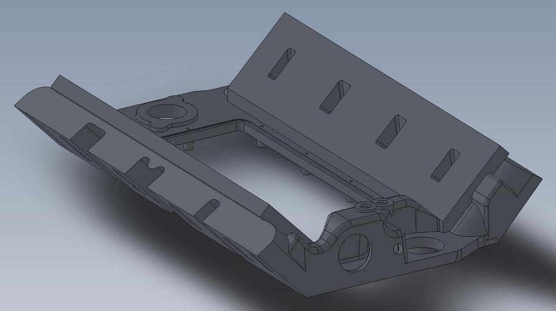
This is a drawing of a partially machined casting, the ports are not finished and the pushrod holes and some of the bolt holes are not shown. The port configuration will depend on what manifold is run on the intake. For example, a standard 351C intake manifolds will get a certain port configuration, the Yates style manifolds will get a different one.
Through this initial design process several things became apparent. My original plan was going to be to make this manifold suitable for use as a medium riser or high riser (with the associated change in the valve cover rail), or have it be able to be machined as a tunnel port. First pass on the drawing showed that to be unrealistic. The reason was the weight of the casting and the machining time. In order to leave the port openings completely out of the casting (so it could be used for a tunnel port base), and to raise the valve cover rail so it could be machined as a high riser, the weight of the casting went up by nearly 10 pounds! This blew the financial side of the project out the window; I want to be able to sell these for right around $400, and the extra material cost plus the extra machining cost for the medium riser version (which I would expect to sell the most of) made this an impossible target. So, I decided to focus for now on the medium riser design, and do a separate (and more expensive) version that could be machined as a high riser or tunnel port later.
Another thing that became obvious after I purchased and measured several different types of 351C intakes was that all of them would need to be modified or machined in some way in order to fit on this adapter. In some cases the modifications are trivial and can be done with a hacksaw; for example, the Weiand 351C tunnel ram is this way. Others, such as the 351C intakes for Yates style cylinder heads, such as the Edelbrock 2991 and 2865 (Glidden Victor) will require a different bolt pattern and a thinner flange on the intake adapter, plus extensive machining on the valley area of the Edelbrock intake in order to fit. This is going to be a one at a time process for me, to develop the machining operations required on the intake adapter to make some of these manifolds fit. Also, since some of these will require extensive work on the manifolds themselves, I decided that I would have to offer that service for the manifolds also.
Along with the fit issues with the different intakes, there are also different port configurations. So, one port configuration in the intake adapter will definitely not fit all. This makes them a little bit less flexible; unless you go with the stock type 351C 4V intakes, you won't be able to swap a lot of intakes back and forth. When I looked into the 351C intake picture I was really surprised at how much variation there was; the small block stuff seems to have multiple port locations (raised ports in particular), plus more than one bolt pattern depending on the heads that are used.
The conclusion was that what this adapter really needs is a specific intake manifold designed to work with it, rather than trying to make some variety of 351C intakes work. Unfortunately that's a ways down the road; I need to get the adapter manufactured before I can think about making an upper manifold for it. But at this point I think a dedicated upper manifold or two would be a great addition.
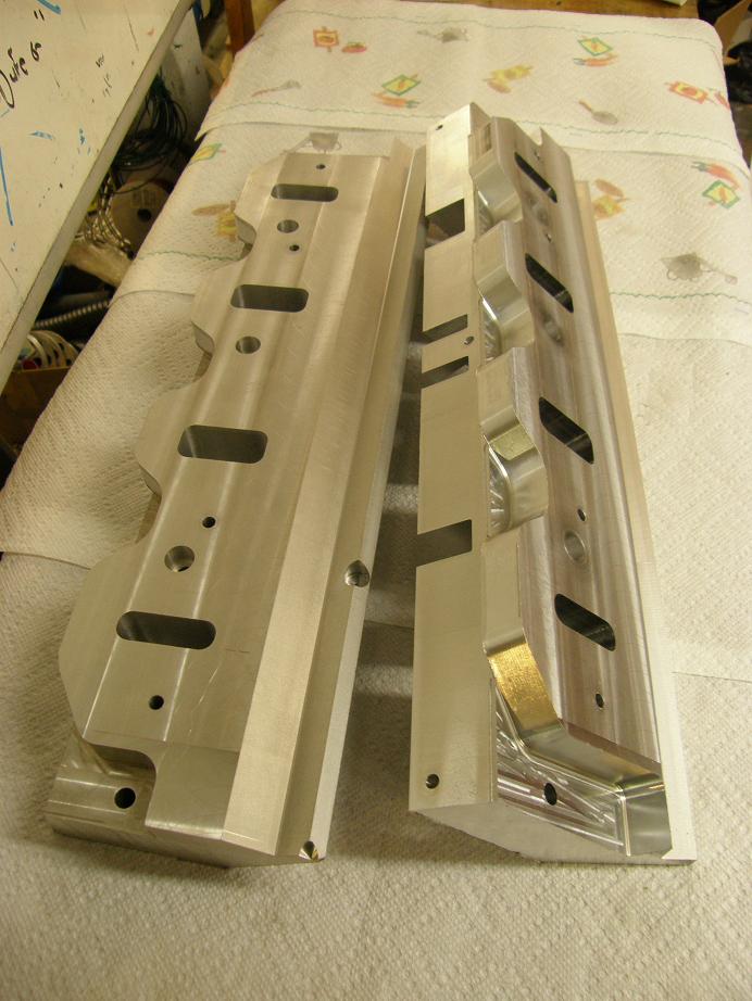
Back to the drawing, which of course you can't bolt onto the engine. As a result, to check the drawing I decided to machine some billet plates with many of the key dimensions of the drawing machined in, to check the fit on a mocked up FE. I'm set up and running now on my new CNC machine, and am starting to get used to writing programs with it, but it still took me the better part of two weeks to write the programs and get the two plates machined. Made some mistakes along the way, but overall I got the key dimensions right. Here is a photo of the two plates, the second of which I just finished up last night:
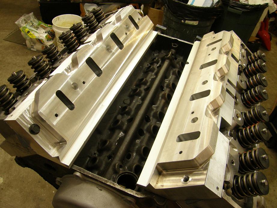
Today I got a spare block and set of Edelbrock heads mocked up, and bolted the plates on to check the fit. I needed to make a slight modification on the drawing with respect to the angle of the valve cover rail, but other than that there were no issues bolting the plates onto the heads:
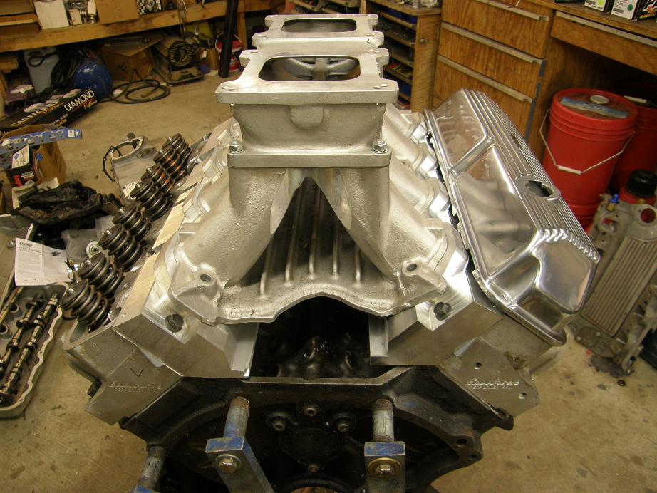
Finally I topped the setup off with the 351C tunnel ram to check port alignment and fit. This was a little more problematic, since I have limited data on 351C engines. I had to move around some of the mounting holes on the drawing to get them lined up with the intake. I also had to machine the thickness of the plates down somewhat, because the manifold originally sat too high on the plates. One of the complications here was the thickness of the 351C intake manifold gaskets. The Mr. Gasket versions were a full 0.110" thick, while the Fel-Pros were a little more standard .062" (like the FE intake gaskets). I don't know how to address this except to live with these tolerances, but I will probably recommend a specific gasket for best fit of the intake on the adapter.
Finally I got the thickness about right and was able to get the 351C manifold positioned on the adapter so it looked like it would fit. Here's a picture of the tunnel ram sitting on the engine:
Next steps are to get the 3D drawing modified to reflect what the test plates have told me, then its off to the pattern shop with the drawings to make the patterns for the casting sand. That is about a 6-8 week process with the shop that I am going to use. After that, I should be able to get five prototypes cast, and then I can work on the complete machining program. We will see what happens as this projects proceeds...


